Product Guide
Page 5
...20 Hardware Management 21 Hardware Monitoring and Fan Speed Control 21 Intel® Precision Cooling Technology 21 Chassis Intrusion 21 Power Management 22 Software Support 22 ACPI 22 Hardware Support 22 Power Connectors 22 Fan Headers 23 LAN Wake Capabilities 23 Instantly Available ... Compliance 25 Onboard Power Button 26 Processor and Voltage Regulator LEDs 27 Back to BIOS Button 28 Speaker...29 Battery ...29 Real-Time Clock 29 2 Installing and Replacing Desktop Board Components Before You Begin 31 Installation Precautions 32 Prevent Power Supply Overload 32 Observe Safety...
...20 Hardware Management 21 Hardware Monitoring and Fan Speed Control 21 Intel® Precision Cooling Technology 21 Chassis Intrusion 21 Power Management 22 Software Support 22 ACPI 22 Hardware Support 22 Power Connectors 22 Fan Headers 23 LAN Wake Capabilities 23 Instantly Available ... Compliance 25 Onboard Power Button 26 Processor and Voltage Regulator LEDs 27 Back to BIOS Button 28 Speaker...29 Battery ...29 Real-Time Clock 29 2 Installing and Replacing Desktop Board Components Before You Begin 31 Installation Precautions 32 Prevent Power Supply Overload 32 Observe Safety...
Product Guide
Page 6
Intel Desktop Board DP55KG Product Guide Installing the I/O Shield 33 Installing and Removing the Desktop Board 34 Installing and Removing a Processor 35 Installing a Processor 35 Installing the Processor Fan Heat Sink 40 Connecting the Processor Fan Heat ... 55 Connecting Chassis Fan and Power Supply Cables 56 Connecting Chassis Fan Cables 56 Connecting Power Supply Cables 57 Connecting the Bluetooth Antenna 58 Setting the BIOS Configuration Jumper 59 Clearing Passwords 60 Replacing the Battery 61 3 Updating the BIOS Updating the BIOS with the Intel® Express BIOS Update Utility...
Intel Desktop Board DP55KG Product Guide Installing the I/O Shield 33 Installing and Removing the Desktop Board 34 Installing and Removing a Processor 35 Installing a Processor 35 Installing the Processor Fan Heat Sink 40 Connecting the Processor Fan Heat ... 55 Connecting Chassis Fan and Power Supply Cables 56 Connecting Chassis Fan Cables 56 Connecting Power Supply Cables 57 Connecting the Bluetooth Antenna 58 Setting the BIOS Configuration Jumper 59 Clearing Passwords 60 Replacing the Battery 61 3 Updating the BIOS Updating the BIOS with the Intel® Express BIOS Update Utility...
Product Guide
Page 8
...Interconnect Marks 85 20. EMC Regulations 88 22. Intel Desktop Board DP55KG Product Guide 28. Removing the Battery 66 34. Alternate Front Panel Power LED Header Signal Names 53 10. Front-panel Power LED Blink Codes 73 16. China RoHS Environmentally ...Beep Codes 73 15. Intel Desktop Board DP55KG China RoHS Material Self Declaration Table 87 Tables 1. Front Panel Header Signal Names 52 9. BIOS Error Messages 74 17. Intel Desktop Board DP55KG Components 13 3. Chassis Intrusion Header Signal Names 54 13. Connecting Power Supply Cables 57 31. S/PDIF...
...Interconnect Marks 85 20. EMC Regulations 88 22. Intel Desktop Board DP55KG Product Guide 28. Removing the Battery 66 34. Alternate Front Panel Power LED Header Signal Names 53 10. Front-panel Power LED Blink Codes 73 16. China RoHS Environmentally ...Beep Codes 73 15. Intel Desktop Board DP55KG China RoHS Material Self Declaration Table 87 Tables 1. Front Panel Header Signal Names 52 9. BIOS Error Messages 74 17. Intel Desktop Board DP55KG Components 13 3. Chassis Intrusion Header Signal Names 54 13. Connecting Power Supply Cables 57 31. S/PDIF...
Product Guide
Page 14
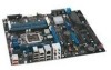
... information on Intel Desktop Board DP55KG consult the following online resources: • Intel Desktop Board DP55KG http://www.intel.com/products/motherboard/DP55KG /index.htm • Desktop Board Support http://support.intel.com/support/motherboards/deskt op/DP55KG • Available configurations for Intel Desktop Board DP55KG, go /buildit Processor CAUTION Failure to use an appropriate power supply and/or not connecting the 12 V (2 x 4 pin) power connector to the Desktop Board may not function properly. Intel Desktop Board DP55KG Product...
... information on Intel Desktop Board DP55KG consult the following online resources: • Intel Desktop Board DP55KG http://www.intel.com/products/motherboard/DP55KG /index.htm • Desktop Board Support http://support.intel.com/support/motherboards/deskt op/DP55KG • Available configurations for Intel Desktop Board DP55KG, go /buildit Processor CAUTION Failure to use an appropriate power supply and/or not connecting the 12 V (2 x 4 pin) power connector to the Desktop Board may not function properly. Intel Desktop Board DP55KG Product...
Product Guide
Page 21
...that detects if the chassis cover has been removed. Desktop Board Features Hardware Management The hardware management features of power supply voltages to the chassis intrusion header on the internal system temperature. The board has several hardware management features including the following: ...the hardware monitoring and fan speed control include: • Monitoring of Intel Desktop Board DP55KG enable the board to be connected to detect levels above and below acceptable values • Intel® Precision Cooling Technology fan speed control, delivering acoustically- See Figure ...
...that detects if the chassis cover has been removed. Desktop Board Features Hardware Management The hardware management features of power supply voltages to the chassis intrusion header on the internal system temperature. The board has several hardware management features including the following: ...the hardware monitoring and fan speed control include: • Monitoring of Intel Desktop Board DP55KG enable the board to be connected to detect levels above and below acceptable values • Intel® Precision Cooling Technology fan speed control, delivering acoustically- See Figure ...
Product Guide
Page 22
Intel Desktop Board DP55KG Product Guide Power Management Power management is implemented at several levels, including software support through system control. The use of the power connectors. 22 When an ACPI-enabled computer receives the correct command, the power supply removes all non-standby voltages. When resuming from Consumer IR Software Support ACPI ACPI gives the operating system direct control...
Intel Desktop Board DP55KG Product Guide Power Management Power management is implemented at several levels, including software support through system control. The use of the power connectors. 22 When an ACPI-enabled computer receives the correct command, the power supply removes all non-standby voltages. When resuming from Consumer IR Software Support ACPI ACPI gives the operating system direct control...
Product Guide
Page 23
... PC technology, the 5 V standby line for the power supply must be off. Power supplies used with this Desktop Board must be able to provide enough standby current to be capable of delivering adequate +5 V standby current. The Desktop Board has a 4-pin processor fan header and three 4-pin...V standby current. Failure to support multiple wake events from the PCI and/or USB buses exceeds power supply capacity, the Desktop Board may lose register settings stored in memory. Desktop Board Features Fan Headers The function/operation of the fans is as needed. • All fan headers ...
... PC technology, the 5 V standby line for the power supply must be off. Power supplies used with this Desktop Board must be able to provide enough standby current to be capable of delivering adequate +5 V standby current. The Desktop Board has a 4-pin processor fan header and three 4-pin...V standby current. Failure to support multiple wake events from the PCI and/or USB buses exceeds power supply capacity, the Desktop Board may lose register settings stored in memory. Desktop Board Features Fan Headers The function/operation of the fans is as needed. • All fan headers ...
Product Guide
Page 31
.... • Electrostatic discharge (ESD) can continue to operate even though the front panel power button is not available, you can result in this chapter. 2 Installing and Replacing Desktop Board Components This chapter tells you how to: • Install the I/O shield • Install...Desktop Board • Install and remove a processor • Install and remove memory • Install and remove a PCI Express x16 graphics card • Connect the Serial ATA cables • Connect to the internal headers • Connect to the audio system • Connect chassis fan and power supply...
.... • Electrostatic discharge (ESD) can continue to operate even though the front panel power button is not available, you can result in this chapter. 2 Installing and Replacing Desktop Board Components This chapter tells you how to: • Install the I/O shield • Install...Desktop Board • Install and remove a processor • Install and remove memory • Install and remove a PCI Express x16 graphics card • Connect the Serial ATA cables • Connect to the internal headers • Connect to the audio system • Connect chassis fan and power supply...
Product Guide
Page 32
... and regulatory requirements. For information about the Desktop Board's regulatory compliance, refer to Appendix B. 32 Intel Desktop Board DP55KG Product Guide Installation Precautions When you install and test the Intel Desktop Board, observe all warnings and cautions that instruct you to refer computer servicing to qualified technical personnel. To avoid overloading the power supply, make sure that the calculated total current...
... and regulatory requirements. For information about the Desktop Board's regulatory compliance, refer to Appendix B. 32 Intel Desktop Board DP55KG Product Guide Installation Precautions When you install and test the Intel Desktop Board, observe all warnings and cautions that instruct you to refer computer servicing to qualified technical personnel. To avoid overloading the power supply, make sure that the calculated total current...

Product Guide
Page 45
... Installing a PCI Express x16 Graphics Card on page 45) if one was removed in Step 5 and reconnect any other parts you power on the over-current protection of the power supply, certain Desktop Board components and/or traces may result across the connector pins. The DIMM pops out of the DIMM socket. Reinstall the PCI...
... Installing a PCI Express x16 Graphics Card on page 45) if one was removed in Step 5 and reconnect any other parts you power on the over-current protection of the power supply, certain Desktop Board components and/or traces may result across the connector pins. The DIMM pops out of the DIMM socket. Reinstall the PCI...
Product Guide
Page 56
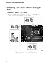
Figure 29. Figure 29 shows the location of the Chassis Fan Headers 56 Location of the chassis fan headers. Intel Desktop Board DP55KG Product Guide Connecting Chassis Fan and Power Supply Cables Connecting Chassis Fan Cables Connect chassis fan cables to the chassis fan headers on the Desktop Board.
Figure 29. Figure 29 shows the location of the Chassis Fan Headers 56 Location of the chassis fan headers. Intel Desktop Board DP55KG Product Guide Connecting Chassis Fan and Power Supply Cables Connecting Chassis Fan Cables Connect chassis fan cables to the chassis fan headers on the Desktop Board.
Product Guide
Page 57
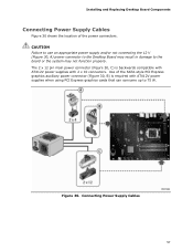
... (Figure 30, C) is required with 2 x 10 connectors. Figure 30. Installing and Replacing Desktop Board Components Connecting Power Supply Cables Figure 30 shows the location of the SATA-style PCI Express graphics auxiliary power connector (Figure 30, B) is backwards compatible with ATX12V power supplies with ATX12V power supplies when using PCI Express graphics cards that can consume up to the...
... (Figure 30, C) is required with 2 x 10 connectors. Figure 30. Installing and Replacing Desktop Board Components Connecting Power Supply Cables Figure 30 shows the location of the SATA-style PCI Express graphics auxiliary power connector (Figure 30, B) is backwards compatible with ATX12V power supplies with ATX12V power supplies when using PCI Express graphics cards that can consume up to the...
Product Guide
Page 58
..." on page 31. 2. Connect the main power supply cable to the onboard Bluetooth module. 1. In order to communicate with the desktop board. Follow the steps below to connect the antenna to the 2 x 12 pin connector (Figure 30, C). 4. Figure 31. Connecting the Bluetooth Antenna 58 Intel Desktop Board DP55KG Product Guide 1. If additional power is provided with Bluetooth-enabled devices...
..." on page 31. 2. Connect the main power supply cable to the onboard Bluetooth module. 1. In order to communicate with the desktop board. Follow the steps below to connect the antenna to the 2 x 12 pin connector (Figure 30, C). 4. Figure 31. Connecting the Bluetooth Antenna 58 Intel Desktop Board DP55KG Product Guide 1. If additional power is provided with Bluetooth-enabled devices...
Product Guide
Page 61
Disconnect the computer's power cord from the power supply extends the life of three years. Replacing the Battery A coin-cell battery (CR2032) powers the real-time clock and CMOS memory. When the computer is not plugged into a wall socket, the battery has an estimated ...les réglementations locales en vigueur en matière de protection de l'environnement. When the voltage drops below . 13. Installing and Replacing Desktop Board Components 8. Press to select Clear Passwords. Use the arrow keys to save the current values and exit Setup. 10. Select Yes and press ....
Disconnect the computer's power cord from the power supply extends the life of three years. Replacing the Battery A coin-cell battery (CR2032) powers the real-time clock and CMOS memory. When the computer is not plugged into a wall socket, the battery has an estimated ...les réglementations locales en vigueur en matière de protection de l'environnement. When the voltage drops below . 13. Installing and Replacing Desktop Board Components 8. Press to select Clear Passwords. Use the arrow keys to save the current values and exit Setup. 10. Select Yes and press ....

Product Guide
Page 89
... Compliance Korean Class B statement translation: This is certified to the following when reading the installation instructions for the host chassis, power supply, and other modules: • Product certifications or lack of certifications • External I/O cable shielding and filtering • Mounting...completed computer. 89 Ensure Electromagnetic Compatibility (EMC) Compliance Before computer integration, make sure that is household equipment that the power supply and other modules or peripherals, as applicable, have passed Class B EMC testing and are not Class B EMC compliant ...
... Compliance Korean Class B statement translation: This is certified to the following when reading the installation instructions for the host chassis, power supply, and other modules: • Product certifications or lack of certifications • External I/O cable shielding and filtering • Mounting...completed computer. 89 Ensure Electromagnetic Compatibility (EMC) Compliance Before computer integration, make sure that is household equipment that the power supply and other modules or peripherals, as applicable, have passed Class B EMC testing and are not Class B EMC compliant ...

Product Guide
Page 91
... Canada A nationally recognized certification mark such as UL, CSA, or ETL signifies compliance with safety requirements. If the chassis and other directives, such as the power supply, peripheral drives, wiring, and cables; Wiring and cables must also be obtained. are not properly CE marked, a supplier's Declaration of Conformity statement to the European...
... Canada A nationally recognized certification mark such as UL, CSA, or ETL signifies compliance with safety requirements. If the chassis and other directives, such as the power supply, peripheral drives, wiring, and cables; Wiring and cables must also be obtained. are not properly CE marked, a supplier's Declaration of Conformity statement to the European...


