Product Guide
Page 5
Contents 1 Desktop Board Features Supported Operating Systems 11 Desktop Board Components 12 Processor ...14 Main Memory...15 Intel® P55 Express Chipset 16 Audio Subsystem 16 LAN Subsystem 16 Bluetooth* Technology Support 17 USB 2.0 Support 17 Serial ATA Support 18 Legacy I/O ...19 Expandability...19 BIOS ...20 Serial ATA Auto ...27 Back to BIOS Button 28 Speaker...29 Battery ...29 Real-Time Clock 29 2 Installing and Replacing Desktop Board Components Before You Begin 31 Installation Precautions 32 Prevent Power Supply Overload 32 Observe Safety and Regulatory Requirements 32 v
Contents 1 Desktop Board Features Supported Operating Systems 11 Desktop Board Components 12 Processor ...14 Main Memory...15 Intel® P55 Express Chipset 16 Audio Subsystem 16 LAN Subsystem 16 Bluetooth* Technology Support 17 USB 2.0 Support 17 Serial ATA Support 18 Legacy I/O ...19 Expandability...19 BIOS ...20 Serial ATA Auto ...27 Back to BIOS Button 28 Speaker...29 Battery ...29 Real-Time Clock 29 2 Installing and Replacing Desktop Board Components Before You Begin 31 Installation Precautions 32 Prevent Power Supply Overload 32 Observe Safety and Regulatory Requirements 32 v
Product Guide
Page 6
Intel Desktop Board DP55KG Product Guide Installing the I/O Shield 33 Installing and Removing the Desktop Board 34 Installing and Removing a Processor 35 Installing a Processor 35 Installing the Processor Fan Heat Sink 40 Connecting the Processor Fan Heat Sink Cable 40 Removing ... ATA (SATA) Cables 49 Connecting to the Internal Headers 50 S/PDIF Header 51 Front Panel Intel HD Audio Header 51 Consumer IR (CIR) Headers 51 Front Panel Header 52 Alternate Front Panel Power LED Header 53 USB 2.0 Headers 53 IEEE 1394a Header 54 Chassis Intrusion Header 54 Connecting to the Audio System...
Intel Desktop Board DP55KG Product Guide Installing the I/O Shield 33 Installing and Removing the Desktop Board 34 Installing and Removing a Processor 35 Installing a Processor 35 Installing the Processor Fan Heat Sink 40 Connecting the Processor Fan Heat Sink Cable 40 Removing ... ATA (SATA) Cables 49 Connecting to the Internal Headers 50 S/PDIF Header 51 Front Panel Intel HD Audio Header 51 Consumer IR (CIR) Headers 51 Front Panel Header 52 Alternate Front Panel Power LED Header 53 USB 2.0 Headers 53 IEEE 1394a Header 54 Chassis Intrusion Header 54 Connecting to the Audio System...
Product Guide
Page 8
Removing the Battery 66 34. Intel Desktop Board DP55KG Components 13 3. S/PDIF Header Signal Names 51 5. Front Panel Header Signal Names 52 9. USB 2.0 Header Signal Names 53 11. BIOS Beep Codes 73 15. Port 80h POST Codes 76 18. Safety Standards 79 19. ... 55 29. POST Code LED Display 75 35. LAN Connector LEDs 17 4. Front Panel CIR Receiver (Input) Header Signal Names 52 7. Intel Desktop Board DP55KG China RoHS Material Self Declaration Table 87 Tables 1. Chassis Intrusion Header Signal Names 54 13. BIOS Error Messages 74 17. Connecting Power Supply Cables...
Removing the Battery 66 34. Intel Desktop Board DP55KG Components 13 3. S/PDIF Header Signal Names 51 5. Front Panel Header Signal Names 52 9. USB 2.0 Header Signal Names 53 11. BIOS Beep Codes 73 15. Port 80h POST Codes 76 18. Safety Standards 79 19. ... 55 29. POST Code LED Display 75 35. LAN Connector LEDs 17 4. Front Panel CIR Receiver (Input) Header Signal Names 52 7. Intel Desktop Board DP55KG China RoHS Material Self Declaration Table 87 Tables 1. Chassis Intrusion Header Signal Names 54 13. BIOS Error Messages 74 17. Connecting Power Supply Cables...
Product Guide
Page 9
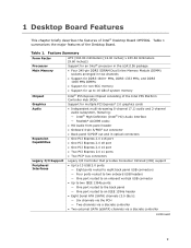
...an onboard vertical USB connector • Up to two IEEE 1394a ports: ― One port routed to the back panel ― One port routed to 16 GB of system memory Chipset Intel® P55 Express Chipset consisting of Intel® Desktop Board DP55KG. 1 Desktop Board Features This ...chapter briefly describes the features of the Intel P55 Platform Controller Hub (PCH) Graphics Audio Expansion Capabilities Support for...
...an onboard vertical USB connector • Up to two IEEE 1394a ports: ― One port routed to the back panel ― One port routed to 16 GB of system memory Chipset Intel® P55 Express Chipset consisting of Intel® Desktop Board DP55KG. 1 Desktop Board Features This ...chapter briefly describes the features of the Intel P55 Platform Controller Hub (PCH) Graphics Audio Expansion Capabilities Support for...
Product Guide
Page 10
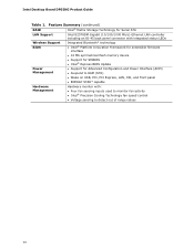
... memory device • Support for SMBIOS • Intel® Express BIOS Update Power Management • Support for Advanced Configuration and Power Interface (ACPI) • Suspend to RAM (STR) • Wake on USB, PCI, PCI Express, LAN, CIR, and front... panel • ENERGY STAR* capable Hardware Management Hardware monitor with: • Four fan sensing inputs used to monitor fan activity • Intel® Precision Cooling Technology fan speed control • Voltage sensing to detect out of range values 10 Intel Desktop Board DP55KG...
... memory device • Support for SMBIOS • Intel® Express BIOS Update Power Management • Support for Advanced Configuration and Power Interface (ACPI) • Suspend to RAM (STR) • Wake on USB, PCI, PCI Express, LAN, CIR, and front... panel • ENERGY STAR* capable Hardware Management Hardware monitor with: • Four fan sensing inputs used to monitor fan activity • Intel® Precision Cooling Technology fan speed control • Voltage sensing to detect out of range values 10 Intel Desktop Board DP55KG...
Product Guide
Page 13
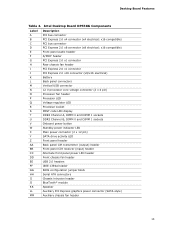
... 2.0 x1 connector PCI Express 2.0 x16 connector (x8/x16 electrical) Battery Back panel connectors Vertical USB connector 12 V processor core voltage connector (2 x 4 pin) Processor fan header Processor LED Voltage... front panel power LED header Front chassis fan header USB 2.0 headers IEEE 1394a header BIOS configuration jumper block Serial ATA connectors Chassis intrusion header BlueTooth* module Speaker Auxiliary PCI Express graphics power connector (SATA-style) Auxiliary chassis fan header 13 Desktop Board Features Table 2. Intel Desktop Board DP55KG Components Label A B C D E F G ...
... 2.0 x1 connector PCI Express 2.0 x16 connector (x8/x16 electrical) Battery Back panel connectors Vertical USB connector 12 V processor core voltage connector (2 x 4 pin) Processor fan header Processor LED Voltage... front panel power LED header Front chassis fan header USB 2.0 headers IEEE 1394a header BIOS configuration jumper block Serial ATA connectors Chassis intrusion header BlueTooth* module Speaker Auxiliary PCI Express graphics power connector (SATA-style) Auxiliary chassis fan header 13 Desktop Board Features Table 2. Intel Desktop Board DP55KG Components Label A B C D E F G ...
Product Guide
Page 17
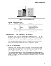
...rate 100 Mb/s data rate 1000 Mb/s data rate Bluetooth* Technology Support The Desktop Board includes an integrated Bluetooth* module (Figure 1, JJ). USB 2.0 Support The Desktop Board provides 13 USB 2.0 ports (eight ports routed to back panel connectors, four ports routed to ...be required to connect the antenna provided with a variety of Bluetooth-enabled devices. USB 2.0 ports are backward compatible with USB 1.1 devices. USB 1.1 devices will function normally at USB 1.1 speeds. Desktop Board Features Figure 2. LAN Connector LEDs Table 3. LAN Connector LEDs LED A B ...
...rate 100 Mb/s data rate 1000 Mb/s data rate Bluetooth* Technology Support The Desktop Board includes an integrated Bluetooth* module (Figure 1, JJ). USB 2.0 Support The Desktop Board provides 13 USB 2.0 ports (eight ports routed to back panel connectors, four ports routed to ...be required to connect the antenna provided with a variety of Bluetooth-enabled devices. USB 2.0 ports are backward compatible with USB 1.1 devices. USB 1.1 devices will function normally at USB 1.1 speeds. Desktop Board Features Figure 2. LAN Connector LEDs Table 3. LAN Connector LEDs LED A B ...
Product Guide
Page 22
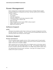
...turn off ). The Desktop Board has three power connectors. When an ACPI-enabled computer receives the correct command, the power supply removes all non-standby voltages. When resuming from an AC power failure, the computer returns to RAM) • +5 V standby power indicator LED • Wake from USB • Power ... can be set by using the Last Power State feature in before power was in the BIOS Setup program's Boot menu. Intel Desktop Board DP55KG Product Guide Power Management Power management is implemented at several levels, including software support through system control.
...turn off ). The Desktop Board has three power connectors. When an ACPI-enabled computer receives the correct command, the power supply removes all non-standby voltages. When resuming from an AC power failure, the computer returns to RAM) • +5 V standby power indicator LED • Wake from USB • Power ... can be set by using the Last Power State feature in before power was in the BIOS Setup program's Boot menu. Intel Desktop Board DP55KG Product Guide Power Management Power management is implemented at several levels, including software support through system control.
Product Guide
Page 23
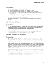
...be capable of delivering adequate +5 V standby current. LAN wakeup capabilities enable remote wake-up the computer. Power supplies used with this Desktop Board must be off when the computer is in the S3 sleep state, the computer will appear to a tachometer input of the hardware ...that powers up of the computer through a network. Instantly Available PC technology enables the board to support multiple wake events from the PCI and/or USB buses exceeds power supply capacity, the Desktop Board may lose register settings stored in memory. The LAN subsystem monitors network traffic and upon...
...be capable of delivering adequate +5 V standby current. LAN wakeup capabilities enable remote wake-up the computer. Power supplies used with this Desktop Board must be off when the computer is in the S3 sleep state, the computer will appear to a tachometer input of the hardware ...that powers up of the computer through a network. Instantly Available PC technology enables the board to support multiple wake events from the PCI and/or USB buses exceeds power supply capacity, the Desktop Board may lose register settings stored in memory. The LAN subsystem monitors network traffic and upon...
Product Guide
Page 25
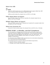
...configurations, go to http://www.intel.com/go/energystar. WAKE# Signal Wake-up Support When the PME# signal on the PCI Express bus is asserted, the computer wakes from an ACPI S1, S3, S4, or S5 state. This Desktop Board meets the ENERGY STAR Program... for Computers: Version 5.0 Category D requirements. The Desktop Board also meets the following international requirements: • Republic of a USB peripheral that supports Wake from USB and an operating system that supports Wake from USB. PME# Signal Wake-up ...
...configurations, go to http://www.intel.com/go/energystar. WAKE# Signal Wake-up Support When the PME# signal on the PCI Express bus is asserted, the computer wakes from an ACPI S1, S3, S4, or S5 state. This Desktop Board meets the ENERGY STAR Program... for Computers: Version 5.0 Category D requirements. The Desktop Board also meets the following international requirements: • Republic of a USB peripheral that supports Wake from USB and an operating system that supports Wake from USB. PME# Signal Wake-up ...
Product Guide
Page 53
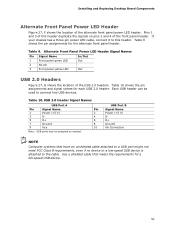
... the alternate front panel header. USB 2.0 Header Signal Names USB Port A Pin Signal Name Pin 1 Power (+5 V) 2 3 D- 4 5 D+ 6 7 Ground 8 9 Key 10 Note: USB ports may be used to this header duplicate the signals on pins 2 and 4 of this header. Pins 1 and 3 of the front panel header. Installing and Replacing Desktop Board Components Alternate Front Panel Power LED...
... the alternate front panel header. USB 2.0 Header Signal Names USB Port A Pin Signal Name Pin 1 Power (+5 V) 2 3 D- 4 5 D+ 6 7 Ground 8 9 Key 10 Note: USB ports may be used to this header duplicate the signals on pins 2 and 4 of this header. Pins 1 and 3 of the front panel header. Installing and Replacing Desktop Board Components Alternate Front Panel Power LED...
Product Guide
Page 67
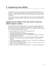
... runs the update program. 6. Go to the DP55KG page, click "[view] Latest BIOS updates," and select the Express BIOS Update utility file. 3. The BIOS file is required. Navigate to the Intel World Wide Web site: http://support.intel.com/support/motherboards/desktop/ 2. Close all other applications. Double-click the... can access the BIOS Setup program by either using the Intel Express BIOS Update utility or the Iflash Memory Update utility, and how to complete the BIOS update. 67 Download the file to a removable USB device. This step is included in the Windows environment. ...
... runs the update program. 6. Go to the DP55KG page, click "[view] Latest BIOS updates," and select the Express BIOS Update utility file. 3. The BIOS file is required. Navigate to the Intel World Wide Web site: http://support.intel.com/support/motherboards/desktop/ 2. Close all other applications. Double-click the... can access the BIOS Setup program by either using the Intel Express BIOS Update utility or the Iflash Memory Update utility, and how to complete the BIOS update. 67 Download the file to a removable USB device. This step is included in the Windows environment. ...
Product Guide
Page 69
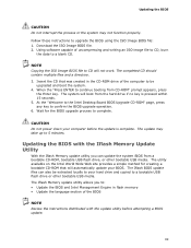
... be extracted locally to your hard drive and copied to a bootable USB flash drive or other bootable USB media. When the "Press ENTER to continue booting from a bootable CD-ROM, bootable USB flash drive, or other bootable USB media. At the "Welcome to the Intel Desktop Board BIOS Upgrade CD-ROM" page, press any key to upgrade...
... be extracted locally to your hard drive and copied to a bootable USB flash drive or other bootable USB media. When the "Press ENTER to continue booting from a bootable CD-ROM, bootable USB flash drive, or other bootable USB media. At the "Welcome to the Intel Desktop Board BIOS Upgrade CD-ROM" page, press any key to upgrade...
Product Guide
Page 70
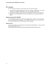
...the root directory will interrupt the BIOS update; however, if an interruption occurs, the BIOS could be required. Due to the USB device. 3. Intel Desktop Board DP55KG Product Guide CAUTION Do not interrupt the process or the system may not function properly. 1. Manually run the IFLASH.EXE file...update file and copy the .BIO file, IFLASH.EXE, and .ITK file (optional) to http://support.intel.com/support/motherboards/desktop/sb/CS-022312.htm 70 Related Links: For more information about updating the Intel Desktop Board BIOS or recovering from the USB device and manually update the BIOS.
...the root directory will interrupt the BIOS update; however, if an interruption occurs, the BIOS could be required. Due to the USB device. 3. Intel Desktop Board DP55KG Product Guide CAUTION Do not interrupt the process or the system may not function properly. 1. Manually run the IFLASH.EXE file...update file and copy the .BIO file, IFLASH.EXE, and .ITK file (optional) to http://support.intel.com/support/motherboards/desktop/sb/CS-022312.htm 70 Related Links: For more information about updating the Intel Desktop Board BIOS or recovering from the USB device and manually update the BIOS.
Product Guide
Page 72
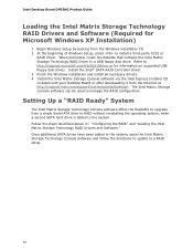
... added to a RAID setup. 72 Intel Desktop Board DP55KG Product Guide Loading the Intel Matrix Storage Technology RAID Drivers and Software (Required for information on supported USB floppy disk drives. Install the Intel Matrix Storage Console software via the Intel Express Installer CD included with your Desktop Board or after downloading it from the Internet at http://support.intel.com/support/motherboards/desktop/.
... added to a RAID setup. 72 Intel Desktop Board DP55KG Product Guide Loading the Intel Matrix Storage Technology RAID Drivers and Software (Required for information on supported USB floppy disk drives. Install the Intel Matrix Storage Console software via the Intel Express Installer CD included with your Desktop Board or after downloading it from the Internet at http://support.intel.com/support/motherboards/desktop/.

Product Guide
Page 77
... bases CPU DXE phase begin to end CPU DXE SMM phase begin to end I/O Buses PCI enumeration, allocation, hot plug Resetting USB bus Resetting SATA bus and all devices Unrecoverable error, start with PIC Boot Device Selection (BDS) BDS driver entry Entered DXE phase... Waiting for user input Checking password Entering BIOS setup Calling legacy option ROMs Keyboard/Mouse (PS/2 or USB) Keyboard initialization Mouse initialization Fixed Media Detecting and initializing fixed media Runtime Phase/EFI Operating System Boot EFI boot service ExitBootServices EFI runtime...
... bases CPU DXE phase begin to end CPU DXE SMM phase begin to end I/O Buses PCI enumeration, allocation, hot plug Resetting USB bus Resetting SATA bus and all devices Unrecoverable error, start with PIC Boot Device Selection (BDS) BDS driver entry Entered DXE phase... Waiting for user input Checking password Entering BIOS setup Calling legacy option ROMs Keyboard/Mouse (PS/2 or USB) Keyboard initialization Mouse initialization Fixed Media Detecting and initializing fixed media Runtime Phase/EFI Operating System Boot EFI boot service ExitBootServices EFI runtime...

