Product Guide
Page 7
...Cover 37 13. Connecting the Processor Fan Heat Sink Power Cable to BIOS Button 28 8. Connecting the Serial ATA Cables 49 27. Intel Desktop Board DP55KG Components 12 2. LAN Connector LEDs 17 3. Onboard Power Button 26 6. Remove the Processor from the Protective Cover 38 14. Example Dual... 24. Removing a PCI Express x16 Graphics Card 47 25. Contents A Error Messages and Indicators BIOS Error Codes 73 BIOS Error Messages 74 Port 80h POST Codes 75 B Regulatory Compliance Safety Standards 79 Place Battery Marking 79 European Union Declaration of Conformity Statement 80 Product ...
...Cover 37 13. Connecting the Processor Fan Heat Sink Power Cable to BIOS Button 28 8. Connecting the Serial ATA Cables 49 27. Intel Desktop Board DP55KG Components 12 2. LAN Connector LEDs 17 3. Onboard Power Button 26 6. Remove the Processor from the Protective Cover 38 14. Example Dual... 24. Removing a PCI Express x16 Graphics Card 47 25. Contents A Error Messages and Indicators BIOS Error Codes 73 BIOS Error Messages 74 Port 80h POST Codes 75 B Regulatory Compliance Safety Standards 79 Place Battery Marking 79 European Union Declaration of Conformity Statement 80 Product ...
Product Guide
Page 8
... Connectors 55 29. Location of the BIOS Configuration Jumper Block 59 33. Connecting the Bluetooth Antenna 58 32. Port 80h POST Codes 76 18. China RoHS Environmentally Friendly Use Period Mark 86 21. Intel Desktop Board DP55KG Components 13 3. Jumper Settings for the BIOS Setup Program Modes 60 14. S/PDIF Header Signal Names 51 5. Front Panel...
... Connectors 55 29. Location of the BIOS Configuration Jumper Block 59 33. Connecting the Bluetooth Antenna 58 32. Port 80h POST Codes 76 18. China RoHS Environmentally Friendly Use Period Mark 86 21. Intel Desktop Board DP55KG Components 13 3. Jumper Settings for the BIOS Setup Program Modes 60 14. S/PDIF Header Signal Names 51 5. Front Panel...
Product Guide
Page 13
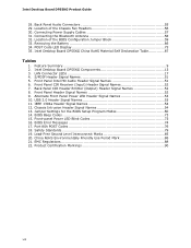
Intel Desktop Board DP55KG Components Label A B C D E F G H I J K L M N O P Q R S T U V W X Y Z AA BB CC DD EE FF GG HH II JJ KK LL MM Description PCI bus connector PCI Express 2.0 x4 connector (x4 electrical; Desktop Board Features Table 2. x16 compatible) PCI bus connector PCI Express 2.0 x8 connector (x8 ... Vertical USB connector 12 V processor core voltage connector (2 x 4 pin) Processor fan header Processor LED Voltage regulator LED Processor socket POST code LED display DDR3 Channel A, DIMM 0 and DIMM 1 sockets DDR3 Channel B, DIMM 0 and DIMM 1 sockets Onboard power button Standby...
Intel Desktop Board DP55KG Components Label A B C D E F G H I J K L M N O P Q R S T U V W X Y Z AA BB CC DD EE FF GG HH II JJ KK LL MM Description PCI bus connector PCI Express 2.0 x4 connector (x4 electrical; Desktop Board Features Table 2. x16 compatible) PCI bus connector PCI Express 2.0 x8 connector (x8 ... Vertical USB connector 12 V processor core voltage connector (2 x 4 pin) Processor fan header Processor LED Voltage regulator LED Processor socket POST code LED display DDR3 Channel A, DIMM 0 and DIMM 1 sockets DDR3 Channel B, DIMM 0 and DIMM 1 sockets Onboard power button Standby...
Product Guide
Page 29
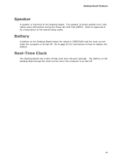
... is turned off . 29 Battery A battery on the Desktop Board. Refer to replace the battery. The speaker provides audible error code (beep code) information during the Power-On Self-Test (POST). Real-Time Clock The Desktop Board has a time-of the board's beep codes. Desktop Board Features Speaker A speaker is mounted on the Desktop Board keeps the values in CMOS RAM and the...
... is turned off . 29 Battery A battery on the Desktop Board. Refer to replace the battery. The speaker provides audible error code (beep code) information during the Power-On Self-Test (POST). Real-Time Clock The Desktop Board has a time-of the board's beep codes. Desktop Board Features Speaker A speaker is mounted on the Desktop Board keeps the values in CMOS RAM and the...
Product Guide
Page 73
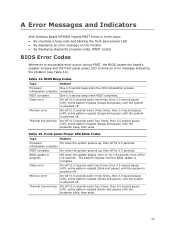
... powers up , then off for 0.5 seconds. A Error Messages and Indicators Intel Desktop Board DP55KG reports POST errors in progress Off when the update begins, then on the monitor • By displaying diagnostic progress codes (POST codes) BIOS Error Codes Whenever a recoverable error occurs during POST, the BIOS causes the board's speaker to beep and the front panel power LED to blink...
... powers up , then off for 0.5 seconds. A Error Messages and Indicators Intel Desktop Board DP55KG reports POST errors in progress Off when the update begins, then on the monitor • By displaying diagnostic progress codes (POST codes) BIOS Error Codes Whenever a recoverable error occurs during POST, the BIOS causes the board's speaker to beep and the front panel power LED to blink...
Product Guide
Page 75
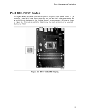
If the POST fails, execution stops and the last POST code generated is useful for determining the point where an error occurred during the POST. Error Messages and Indicators Port 80h POST Codes During the POST, the BIOS generates diagnostic progress codes (POST codes) to I/O port 80h. POST Code LED Display 75 This code is left at port 80h and displayed on the Desktop Board's seven-segment LED display shown in Figure 34. Figure 34.
If the POST fails, execution stops and the last POST code generated is useful for determining the point where an error occurred during the POST. Error Messages and Indicators Port 80h POST Codes During the POST, the BIOS generates diagnostic progress codes (POST codes) to I/O port 80h. POST Code LED Display 75 This code is left at port 80h and displayed on the Desktop Board's seven-segment LED display shown in Figure 34. Figure 34.
Product Guide
Page 76
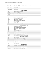
Port 80h POST Codes POST Code Description 00 01-05 10, 20, 30, 40, 50 ACPI S States Entering S0 state, standard Entering S1-S5 state Resuming from S1-S5 state 08 ... 29 Exit MRC driver 2A, 2B PEI After MRC Start/finish programming MTRR settings 31, 33, 34 PEIMs/Recovery Recovery has initiate, load, valid 76 Intel Desktop Board DP55KG Product Guide Table 17 lists the Port 80h POST codes in hexadecimal notation. Table 17.
Port 80h POST Codes POST Code Description 00 01-05 10, 20, 30, 40, 50 ACPI S States Entering S0 state, standard Entering S1-S5 state Resuming from S1-S5 state 08 ... 29 Exit MRC driver 2A, 2B PEI After MRC Start/finish programming MTRR settings 31, 33, 34 PEIMs/Recovery Recovery has initiate, load, valid 76 Intel Desktop Board DP55KG Product Guide Table 17 lists the Port 80h POST codes in hexadecimal notation. Table 17.

Product Guide
Page 77
Error Messages and Indicators POST Code 41-43 44-46 47-4C 4D-4F 50-52 58, 59 5A, 5B 5F 60-6F E4 E7 E8 E9 EB 90-95 98-...
Error Messages and Indicators POST Code 41-43 44-46 47-4C 4D-4F 50-52 58, 59 5A, 5B 5F 60-6F E4 E7 E8 E9 EB 90-95 98-...


