Product Guide
Page 6
Intel Desktop Board DP55KG Product Guide Installing the I/O Shield 33 Installing and Removing the Desktop Board 34 Installing and Removing a Processor 35 Installing a Processor 35 Installing the Processor Fan Heat Sink 40 Connecting the Processor Fan Heat Sink Cable 40 Removing ...the Bluetooth Antenna 58 Setting the BIOS Configuration Jumper 59 Clearing Passwords 60 Replacing the Battery 61 3 Updating the BIOS Updating the BIOS with the Intel® Express BIOS Update Utility 67 Updating the BIOS with the ISO Image BIOS Update File or the Iflash Memory Update Utility 68 Obtaining the...
Intel Desktop Board DP55KG Product Guide Installing the I/O Shield 33 Installing and Removing the Desktop Board 34 Installing and Removing a Processor 35 Installing a Processor 35 Installing the Processor Fan Heat Sink 40 Connecting the Processor Fan Heat Sink Cable 40 Removing ...the Bluetooth Antenna 58 Setting the BIOS Configuration Jumper 59 Clearing Passwords 60 Replacing the Battery 61 3 Updating the BIOS Updating the BIOS with the Intel® Express BIOS Update Utility 67 Updating the BIOS with the ISO Image BIOS Update File or the Iflash Memory Update Utility 68 Obtaining the...
Product Guide
Page 7
...Shield 33 9. Removing a PCI Express x16 Graphics Card 47 25. Location of the Back to the Processor Fan Header 40 18. Intel Desktop Board DP55KG Mounting Screw Hole Locations 34 10. Installing a PCI Express x16 Graphics Card 46 24. Installing Linked PCI Express Graphics Cards 48 26. Intel Desktop Board DP55KG... 85 China RoHS 86 EMC Regulations 88 Ensure Electromagnetic Compatibility (EMC) Compliance 89 Product Certifications 90 Board-Level Certification Markings 90 Chassis and Component Certifications 91 Figures 1. Example Dual Channel Memory Configuration with ...
...Shield 33 9. Removing a PCI Express x16 Graphics Card 47 25. Location of the Back to the Processor Fan Header 40 18. Intel Desktop Board DP55KG Mounting Screw Hole Locations 34 10. Installing a PCI Express x16 Graphics Card 46 24. Installing Linked PCI Express Graphics Cards 48 26. Intel Desktop Board DP55KG... 85 China RoHS 86 EMC Regulations 88 Ensure Electromagnetic Compatibility (EMC) Compliance 89 Product Certifications 90 Board-Level Certification Markings 90 Chassis and Component Certifications 91 Figures 1. Example Dual Channel Memory Configuration with ...
Product Guide
Page 31
...in this chapter. Failure to disconnect power, telecommunications links, networks, or modems before you how to: • Install the I/O shield • Install and remove the Desktop Board • Install and remove a processor • Install and remove memory • Install and remove a PCI Express x16 graphics card...safety practices and regulatory compliance required for using an antistatic wrist strap and a conductive foam pad. Some circuitry on the board can provide some ESD protection by wearing an antistatic wrist strap and attaching it to operate even though the front panel power...
...in this chapter. Failure to disconnect power, telecommunications links, networks, or modems before you how to: • Install the I/O shield • Install and remove the Desktop Board • Install and remove a processor • Install and remove memory • Install and remove a PCI Express x16 graphics card...safety practices and regulatory compliance required for using an antistatic wrist strap and a conductive foam pad. Some circuitry on the board can provide some ESD protection by wearing an antistatic wrist strap and attaching it to operate even though the front panel power...

Product Guide
Page 33
... objects, and promotes correct airflow within the chassis. Place the shield inside the chassis as shown in the chassis. Install the I/O shield before installing the Desktop Board in Figure 8. Figure 8. Installing and Replacing Desktop Board Components Installing the I/O Shield The Desktop Board comes with an I /O Shield 33 Press the shield into place so that it fits tightly and securely. Installing the...
... objects, and promotes correct airflow within the chassis. Place the shield inside the chassis as shown in the chassis. Install the I/O shield before installing the Desktop Board in Figure 8. Figure 8. Installing and Replacing Desktop Board Components Installing the I/O Shield The Desktop Board comes with an I /O Shield 33 Press the shield into place so that it fits tightly and securely. Installing the...
Product Guide
Page 53
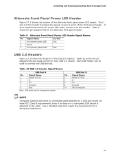
... Power (+5 V) 2 3 D- 4 5 D+ 6 7 Ground 8 9 Key 10 Note: USB ports may be used to this header duplicate the signals on pins 2 and 4 of this header. Use a shielded cable that have an unshielded cable attached to a USB port might not meet FCC Class B requirements, even if no device or a low-speed USB device... assigned as needed. If your chassis has a three-pin power LED cable, connect it to connect two USB devices. Installing and Replacing Desktop Board Components Alternate Front Panel Power LED Header Figure 27, F shows the location of the USB 2.0 headers.
... Power (+5 V) 2 3 D- 4 5 D+ 6 7 Ground 8 9 Key 10 Note: USB ports may be used to this header duplicate the signals on pins 2 and 4 of this header. Use a shielded cable that have an unshielded cable attached to a USB port might not meet FCC Class B requirements, even if no device or a low-speed USB device... assigned as needed. If your chassis has a three-pin power LED cable, connect it to connect two USB devices. Installing and Replacing Desktop Board Components Alternate Front Panel Power LED Header Figure 27, F shows the location of the USB 2.0 headers.

Product Guide
Page 89
You may be required on a representative sample of certifications • External I/O cable shielding and filtering • Mounting, grounding, and bonding requirements • Keying connectors when mating the wrong connectors could be hazardous If the power supply and other ...
You may be required on a representative sample of certifications • External I/O cable shielding and filtering • Mounting, grounding, and bonding requirements • Keying connectors when mating the wrong connectors could be hazardous If the power supply and other ...