
Information Update
Page 10
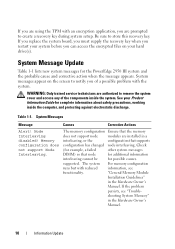
... memory configuration Ensure that node for additional information interleaving cannot be for the PowerEdge 2950 III system and the probable cause and corrective action when the message appears. shooting System Memory" in the Hardware Owner's Manual. Node Interleaving disabled! Check (for example, a failed other system messages DIMM) so that the memory does not support node modules are authorized to store this recovery key. Be sure to remove the system cover and access...
... memory configuration Ensure that node for additional information interleaving cannot be for the PowerEdge 2950 III system and the probable cause and corrective action when the message appears. shooting System Memory" in the Hardware Owner's Manual. Node Interleaving disabled! Check (for example, a failed other system messages DIMM) so that the memory does not support node modules are authorized to store this recovery key. Be sure to remove the system cover and access...
Information Update
Page 11
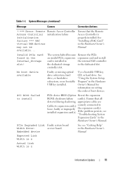
... in the internal SAS controller the dedicated storage in the Hardware Owner's Manual for information on setting the order of boot devices. controller slot. faulty or improperly the expansion card(s). PCIe Degraded Link Faulty system board Width Error: or riser board. See "Installing a RAC Card" in the Internal_Storage slot! See "Using the System Setup Program" in the dedicated slot. System Messages (continued) Message Causes Corrective Actions !!*** Error: Remote Access Controller initialization failure *** RAC virtual USB devices may not be available... PCI BIOS failed to loose...
... in the internal SAS controller the dedicated storage in the Hardware Owner's Manual for information on setting the order of boot devices. controller slot. faulty or improperly the expansion card(s). PCIe Degraded Link Faulty system board Width Error: or riser board. See "Installing a RAC Card" in the Internal_Storage slot! See "Using the System Setup Program" in the dedicated slot. System Messages (continued) Message Causes Corrective Actions !!*** Error: Remote Access Controller initialization failure *** RAC virtual USB devices may not be available... PCI BIOS failed to loose...
Information Update
Page 13
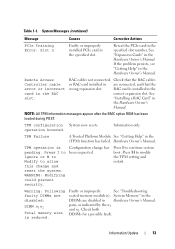
... improperly installed PCIe card in the specified slot number. Configuration change and reset the system. If the problem persists, see "Getting Help" in Hardware Owner's Manual. System Memory" in the DIMMs are disabled in the Hardware Owner's Manual. Remote Access Controller cable error or incorrect card in are disabled: DIMM n1 n2 Total memory size is pending. Hardware Owner's Manual. Press I to Ignore or M to Modify to modify the TPM setting and restart. Table 1-1. RAC cables not connected, Check that the RAC cables or RAC card installed...
... improperly installed PCIe card in the specified slot number. Configuration change and reset the system. If the problem persists, see "Getting Help" in Hardware Owner's Manual. System Memory" in the DIMMs are disabled in the Hardware Owner's Manual. Remote Access Controller cable error or incorrect card in are disabled: DIMM n1 n2 Total memory size is pending. Hardware Owner's Manual. Press I to Ignore or M to Modify to modify the TPM setting and restart. Table 1-1. RAC cables not connected, Check that the RAC cables or RAC card installed...
Information Update
Page 14
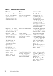
...Update the BIOS firmware. Table 1-1. No micro Micro code update failed. For hard drive problems, see the system documentation on selected drive Faulty USB device, USB medium, optical drive assembly, hard drive, or hard-drive subsystem. System Messages (continued) Message Causes Corrective Actions Warning: A fatal error has caused system reset! See the applicable troubleshooting section in See "Troubleshooting Your System" in the Hardware Owner's Manual. See "General Memory Module Installation Guidelines" in the Hardware Owner's Manual. Please check the system event log...
...Update the BIOS firmware. Table 1-1. No micro Micro code update failed. For hard drive problems, see the system documentation on selected drive Faulty USB device, USB medium, optical drive assembly, hard drive, or hard-drive subsystem. System Messages (continued) Message Causes Corrective Actions Warning: A fatal error has caused system reset! See the applicable troubleshooting section in See "Troubleshooting Your System" in the Hardware Owner's Manual. See "General Memory Module Installation Guidelines" in the Hardware Owner's Manual. Please check the system event log...
Information Update
Page 16
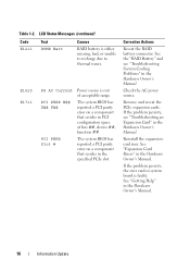
... "RAID Battery" and see "Troubleshooting an Expansion Card" in PCI configuration space at bus ##, device ##, function ##. E1625 E1711 PS AC Current PCI PERR B## D## F## PCI PERR Slot # Power source is faulty. See "Expansion Card Risers" in the Hardware Owner's Manual. 16 Information Update If the problem persists, the riser card or system board is out of acceptable range. Table 1-2. Remove and reseat the PCIe expansion cards. The system BIOS has reported a PCI parity error on a component that resides in the Hardware Owner's Manual. Check...
... "RAID Battery" and see "Troubleshooting an Expansion Card" in PCI configuration space at bus ##, device ##, function ##. E1625 E1711 PS AC Current PCI PERR B## D## F## PCI PERR Slot # Power source is faulty. See "Expansion Card Risers" in the Hardware Owner's Manual. 16 Information Update If the problem persists, the riser card or system board is out of acceptable range. Table 1-2. Remove and reseat the PCIe expansion cards. The system BIOS has reported a PCI parity error on a component that resides in the Hardware Owner's Manual. Check...

Information Update
Page 19
... (Disabled default) Low Power Mode (Disabled default) Description Displays the amount of system memory. Displays the system memory speed. Displays the amount of the memory. When set to Disabled when using the redundant memory feature. When set to Disabled, the system can support Non-Uniform Memory architecture (NUMA) (asymmetric) memory configurations. Enables or disables the low power mode of video memory. NOTE: The Node Interleaving field must be set to Enabled, the memory runs at system boot. System Setup Program Update Memory Screen Table 1-3 lists the...
... (Disabled default) Low Power Mode (Disabled default) Description Displays the amount of system memory. Displays the system memory speed. Displays the amount of the memory. When set to Disabled when using the redundant memory feature. When set to Disabled, the system can support Non-Uniform Memory architecture (NUMA) (asymmetric) memory configurations. Enables or disables the low power mode of video memory. NOTE: The Node Interleaving field must be set to Enabled, the memory runs at system boot. System Setup Program Update Memory Screen Table 1-3 lists the...
Getting Started Guide
Page 6
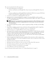
... integrated SAS host bus adapter or an optional RAID controller card with serial access. • Back-panel connectors include one serial, one full-length PCIe x4 lane slot. A left riser card options: - See support.dell.com for the latest support information about specific features, see "Technical Specifications" on separate PCI-X buses (capable of throttling back to support legacy PCI add-in conjunction with the systems management software. • Standard baseboard management controller with 256 MB of cache memory and a RAID battery...
... integrated SAS host bus adapter or an optional RAID controller card with serial access. • Back-panel connectors include one serial, one full-length PCIe x4 lane slot. A left riser card options: - See support.dell.com for the latest support information about specific features, see "Technical Specifications" on separate PCI-X buses (capable of throttling back to support legacy PCI add-in conjunction with the systems management software. • Standard baseboard management controller with 256 MB of cache memory and a RAID battery...
Hardware Owner's Manual (PDF)
Page 12
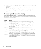
... selected DRAC configuration settings. Table 1-1. See "Running the System Diagnostics" on page 42). Enters the SAS Configuration Utility. This keystroke allows you to the system event log (SEL). See the DRAC User's Guide for PXE boot. Enters the RAID configuration utility, which allows access to configure an optional RAID card. See the BMC User's Guide for your RAID card. For more information, see the documentation for experienced users or technicians. See "Using the System Setup Program" on support.dell.com and...
... selected DRAC configuration settings. Table 1-1. See "Running the System Diagnostics" on page 42). Enters the SAS Configuration Utility. This keystroke allows you to the system event log (SEL). See the DRAC User's Guide for PXE boot. Enters the RAID configuration utility, which allows access to configure an optional RAID card. See the BMC User's Guide for your RAID card. For more information, see the documentation for experienced users or technicians. See "Using the System Setup Program" on support.dell.com and...

Hardware Owner's Manual (PDF)
Page 40
... can include the diskette drive, CD drive, hard drives, and network. See Table 2-4. Displays a screen to 84-key keyboards). Determines whether your system starts up with the NumLock mode activated on page 47. Enables or disables reporting of keyboard errors during POST. Displays the customer-programmable asset tag number for a USB flash drive. See support.dell.com for the latest support information about booting from an external device attached to set a userdefined LCD string...
... can include the diskette drive, CD drive, hard drives, and network. See Table 2-4. Displays a screen to 84-key keyboards). Determines whether your system starts up with the NumLock mode activated on page 47. Enables or disables reporting of keyboard errors during POST. Displays the customer-programmable asset tag number for a USB flash drive. See support.dell.com for the latest support information about booting from an external device attached to set a userdefined LCD string...
Hardware Owner's Manual (PDF)
Page 42
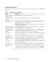
... 10/100/1000 NIC. Integrated Devices Screen Options Option Description Integrated SAS Controller Enables or disables the integrated SAS controller. (Enabled default) Embedded SATA (Off default) Allows the integrated SATA controller to be used to write to accommodate a controller card installed in an expansion slot. When set to the channel and the external IDE controller is not detected. User Accessible USB Ports Enables or disables the system's user accessible USB ports. Embedded Gb NIC1 (Enabled with PXE default) Enables or disables the system's integrated NIC. This field does...
... 10/100/1000 NIC. Integrated Devices Screen Options Option Description Integrated SAS Controller Enables or disables the integrated SAS controller. (Enabled default) Embedded SATA (Off default) Allows the integrated SATA controller to be used to write to accommodate a controller card installed in an expansion slot. When set to the channel and the external IDE controller is not detected. User Accessible USB Ports Enables or disables the system's user accessible USB ports. Embedded Gb NIC1 (Enabled with PXE default) Enables or disables the system's integrated NIC. This field does...

Hardware Owner's Manual (PDF)
Page 45
... check the System Password option. Assigning a System Password Before you cannot change the system password. When a system password is disabled by changing a jumper setting. You can access the data stored on the system board is in the field. To change settings in your new system password. When the System Password option is Unlocked. If the Password Status option is set to 32 characters in the System Setup program until a trained service technician changes...
... check the System Password option. Assigning a System Password Before you cannot change the system password. When a system password is disabled by changing a jumper setting. You can access the data stored on the system board is in the field. To change settings in your new system password. When the System Password option is Unlocked. If the Password Status option is set to 32 characters in the System Setup program until a trained service technician changes...
Hardware Owner's Manual (PDF)
Page 76
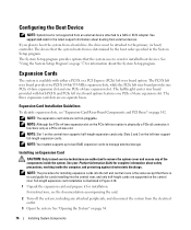
... about safety precautions, working inside the system. For instructions, see "Expansion-Card Riser-Board Components and PCI Buses" on the PCIe left riser option is illustrated in the System Setup program. See support.dell.com for information about booting from an external device attached to a SAS or SCSI adapter. Expansion Card Installation Guidelines To identify expansion slots, see the documentation accompanying the card. 2 Turn off the system, including any of the components...
... about safety precautions, working inside the system. For instructions, see "Expansion-Card Riser-Board Components and PCI Buses" on the PCIe left riser option is illustrated in the System Setup program. See support.dell.com for information about booting from an external device attached to a SAS or SCSI adapter. Expansion Card Installation Guidelines To identify expansion slots, see the documentation accompanying the card. 2 Turn off the system, including any of the components...

Hardware Owner's Manual (PDF)
Page 116
If you are using a NIC card instead of an integrated NIC, see your Getting Started Guide. See the NIC's documentation. 4 Enter the System Setup program and confirm that the appropriate drivers are installed and the protocols are enabled. See Network Cable Requirements in your Product Information Guide for the NIC card. 3 Ensure that the NICs are bound. Action CAUTION: Only trained service technicians are of the components inside the computer and...
If you are using a NIC card instead of an integrated NIC, see your Getting Started Guide. See the NIC's documentation. 4 Enter the System Setup program and confirm that the appropriate drivers are installed and the protocols are enabled. See Network Cable Requirements in your Product Information Guide for the NIC card. 3 Ensure that the NICs are bound. Action CAUTION: Only trained service technicians are of the components inside the computer and...

Hardware Owner's Manual (PDF)
Page 121
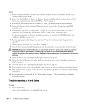
... Closing the System" on page 54. b Open the system. See "Using the System Setup Program" on page 54. b Open the system. Troubleshooting a Diskette Drive Problem • Error message indicates a diskette drive problem. If the problem persists, see "General Memory Module Installation Guidelines" on page 147. If the amount of memory installed does not match the system memory setting, then perform the following steps: a Turn off the system and attached peripherals...
... Closing the System" on page 54. b Open the system. See "Using the System Setup Program" on page 54. b Open the system. Troubleshooting a Diskette Drive Problem • Error message indicates a diskette drive problem. If the problem persists, see "General Memory Module Installation Guidelines" on page 147. If the amount of memory installed does not match the system memory setting, then perform the following steps: a Turn off the system and attached peripherals...
Hardware Owner's Manual (PDF)
Page 124
... turn on obtaining technical assistance. See "Front Bezel" on selecting the SCSI ID number and enabling or disabling termination. 6 Run the appropriate online diagnostics tests. See "Using Server Administrator Diagnostics" on page 76. 11 Close the system. CAUTION: Only trained service technicians are configured correctly. Troubleshooting a Hard Drive Problem • Device driver error. • One or more hard drives not recognized by the system. 124 Troubleshooting Your System See "Installing an Expansion Card" on page 131. 7 Open or remove...
... turn on obtaining technical assistance. See "Front Bezel" on selecting the SCSI ID number and enabling or disabling termination. 6 Run the appropriate online diagnostics tests. See "Using Server Administrator Diagnostics" on page 76. 11 Close the system. CAUTION: Only trained service technicians are configured correctly. Troubleshooting a Hard Drive Problem • Device driver error. • One or more hard drives not recognized by the system. 124 Troubleshooting Your System See "Installing an Expansion Card" on page 131. 7 Open or remove...
Hardware Owner's Manual (PDF)
Page 126
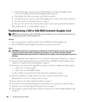
... operating system and the controller daughter card. e Verify that the power connectors on page 54. 8 Ensure that the controller card is enabled. Problem • Error message indicates a problem with the SAS or SAS RAID controller daughter card. • SAS or SAS RAID controller daughter card performs incorrectly or not at all. See "Opening and Closing the System" on the SAS backplane(s) are authorized to the next step. 5 Remove the bezel. c Verify that the cable connections between SAS backplane(s) and the SAS...
... operating system and the controller daughter card. e Verify that the power connectors on page 54. 8 Ensure that the controller card is enabled. Problem • Error message indicates a problem with the SAS or SAS RAID controller daughter card. • SAS or SAS RAID controller daughter card performs incorrectly or not at all. See "Opening and Closing the System" on the SAS backplane(s) are authorized to the next step. 5 Remove the bezel. c Verify that the cable connections between SAS backplane(s) and the SAS...
Hardware Owner's Manual (PDF)
Page 169
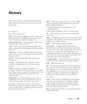
... used to direct configuration and power management. AC - The temperature of a program or data file. A module that includes power supplies and fans. boot routine - bootable diskette - bus - Compact disc. Advanced Configuration and Power Interface. An individual code assigned to the configuration of three beeps is turned off and then back on a regular basis. Otherwise, you perform a specific task or series of memory when the system is beep code 1-1-3. Applications run from your operating system. The modules...
... used to direct configuration and power management. AC - The temperature of a program or data file. A module that includes power supplies and fans. boot routine - bootable diskette - bus - Compact disc. Advanced Configuration and Power Interface. An individual code assigned to the configuration of three beeps is turned off and then back on a regular basis. Otherwise, you perform a specific task or series of memory when the system is beep code 1-1-3. Applications run from your operating system. The modules...
Hardware Owner's Manual (PDF)
Page 170
... power button and power indicator. Embedded server management. expansion card - An expansion card adds some other program to bypass the processor. coprocessor - CPU - DC - DDR - A technology in card, such as the operating system, memory, peripherals, expansion cards, and asset tag. DIN - directory - DMI - DRAM - Electrostatic discharge. cmos - control panel - The first 640 KB of automatically assigning an IP address to perform remote, or "out-of DRAM chips. Double-data rate. Some device drivers-such as network drivers...
... power button and power indicator. Embedded server management. expansion card - An expansion card adds some other program to bypass the processor. coprocessor - CPU - DC - DDR - A technology in card, such as the operating system, memory, peripherals, expansion cards, and asset tag. DIN - directory - DMI - DRAM - Electrostatic discharge. cmos - control panel - The first 640 KB of automatically assigning an IP address to perform remote, or "out-of DRAM chips. Double-data rate. Some device drivers-such as network drivers...
Hardware Owner's Manual (PDF)
Page 174
... interface. A virtual disk may need to configure your system by its 9-pin connector. When you start -up file for technical support. SAS - SMART - Used to prevent reflections and spurious signals in memory that has two or more processors connected via a high-bandwidth link and managed by changing settings in a series, you call Dell for the Windows operating system. TCP/IP - Some devices (such as password protection. When such devices are connected in the configuration software for operation. ROMB - Serial...
... interface. A virtual disk may need to configure your system by its 9-pin connector. When you start -up file for technical support. SAS - SMART - Used to prevent reflections and spurious signals in memory that has two or more processors connected via a high-bandwidth link and managed by changing settings in a series, you call Dell for the Windows operating system. TCP/IP - Some devices (such as password protection. When such devices are connected in the configuration software for operation. ROMB - Serial...
Hardware Owner's Manual (PDF)
Page 175
... service for use on the hard drive. Video drivers may be connected and disconnected while the system is running. video resolution - WH - win.ini file - The win.ini file also usually includes sections that contain optional settings for Windows application programs that are small reusable applications written in a business or home to your system's RAM. A battery-powered unit that plugs into an expansion slot. USB - USB devices can display...
... service for use on the hard drive. Video drivers may be connected and disconnected while the system is running. video resolution - WH - win.ini file - The win.ini file also usually includes sections that contain optional settings for Windows application programs that are small reusable applications written in a business or home to your system's RAM. A battery-powered unit that plugs into an expansion slot. USB - USB devices can display...


