

Installing a SATA Optical Drive
Page 3
... an existing PATA or IDE optical drive is being replaced by a SATA optical drive. See your Hardware Owner's Manual. 4 PowerEdge 1950 systems only: Disconnect and remove the SAS controller...a SATA Optical Drive These instructions apply to Dell™ PowerEdge™ systems to remove the system cover and access any of the optical drive. 6 PowerEdge 2900 and 1900 systems only: Perform the ...power cables from the center fan bracket. See "Opening the System" in your Hardware Owner's Manual. 3 Remove the system cover. b Remove the center fans and the center fan bracket. See "Removing ...
... an existing PATA or IDE optical drive is being replaced by a SATA optical drive. See your Hardware Owner's Manual. 4 PowerEdge 1950 systems only: Disconnect and remove the SAS controller...a SATA Optical Drive These instructions apply to Dell™ PowerEdge™ systems to remove the system cover and access any of the optical drive. 6 PowerEdge 2900 and 1900 systems only: Perform the ...power cables from the center fan bracket. See "Opening the System" in your Hardware Owner's Manual. 3 Remove the system cover. b Remove the center fans and the center fan bracket. See "Removing ...

Installing a SATA Optical Drive
Page 6
See Figure 1-3. PowerEdge 1950 1 Insert the optical drive tray into the system until it is fully inserted and locked into the cable path on the system board. 6 Installing a SATA Optical Drive a Route the cable through the power cable cutout in the fan bracket and follow...SATA cable (the end with a cable provided in a PowerEdge 1950 Drive Tray 2 3 1 4 5 1 optical drive 3 SATA power cable 5 optical drive carrier 2 SATA cable 4 carrier latch Installing the SATA Optical Drive - Figure 1-2. NOTE: You may need to replace the existing power cable with the branching power cable) to ...
See Figure 1-3. PowerEdge 1950 1 Insert the optical drive tray into the system until it is fully inserted and locked into the cable path on the system board. 6 Installing a SATA Optical Drive a Route the cable through the power cable cutout in the fan bracket and follow...SATA cable (the end with a cable provided in a PowerEdge 1950 Drive Tray 2 3 1 4 5 1 optical drive 3 SATA power cable 5 optical drive carrier 2 SATA cable 4 carrier latch Installing the SATA Optical Drive - Figure 1-2. NOTE: You may need to replace the existing power cable with the branching power cable) to ...

Installing a SATA Optical Drive
Page 9
...and the other to the CD/TBU connector on the system and attached peripherals. For a PowerEdge 2900 system, connect to the power supply as follows: - See "Replacing the Center Fan Bracket" in your Hardware Owner's Manual. 11 Reconnect the system to an available power ...supply cable. 5 Replace the center fan bracket. Installing a SATA Optical Drive 9 Installing the SATA Optical Drive - For a PowerEdge 2900, use the SATA_D connector. 9 Replace the cooling shroud. See "Closing the System" in your Hardware Owner's Manual. ...
...and the other to the CD/TBU connector on the system and attached peripherals. For a PowerEdge 2900 system, connect to the power supply as follows: - See "Replacing the Center Fan Bracket" in your Hardware Owner's Manual. 11 Reconnect the system to an available power ...supply cable. 5 Replace the center fan bracket. Installing a SATA Optical Drive 9 Installing the SATA Optical Drive - For a PowerEdge 2900, use the SATA_D connector. 9 Replace the cooling shroud. See "Closing the System" in your Hardware Owner's Manual. ...
Hardware Owner's Manual (PDF)
Page 5
... Cooling Shroud 66 Removing the Cooling Shroud 67 Installing the Cooling Shroud 67 Fan Brackets 68 Removing the Fan Bracket 68 Replacing the Fan Bracket 69 SAS Controller Daughter Card 69 Installing a SAS Controller Daughter Card 70 SAS and SAS RAID Controller Daughter Card Cabling Guidelines . . . ... Guidelines 76 Installing an Expansion Card 76 Removing an Expansion Card 78 Expansion-Card Cage 78 Removing the Expansion-Card Cage 78 Replacing the Expansion-Card Cage 79 Installing a RAC Card 80 Optical Drive 81 Removing the Optical Drive 81 Installing the Optical Drive ...
... Cooling Shroud 66 Removing the Cooling Shroud 67 Installing the Cooling Shroud 67 Fan Brackets 68 Removing the Fan Bracket 68 Replacing the Fan Bracket 69 SAS Controller Daughter Card 69 Installing a SAS Controller Daughter Card 70 SAS and SAS RAID Controller Daughter Card Cabling Guidelines . . . ... Guidelines 76 Installing an Expansion Card 76 Removing an Expansion Card 78 Expansion-Card Cage 78 Removing the Expansion-Card Cage 78 Replacing the Expansion-Card Cage 79 Installing a RAC Card 80 Optical Drive 81 Removing the Optical Drive 81 Installing the Optical Drive ...
Hardware Owner's Manual (PDF)
Page 27
charge left. In contrast, you might be able to remove the message from another source that the RAID Replace RAID battery. Turn off the system and disconnect it from the LCD. Messages will reappear under the following conditions: • The sensor returns to the...cable, and restart the system. Solving Problems Described by deleting event entries. Removing LCD Status Messages For faults associated with sensors, such as temperature, voltage, fans, and so on the LCD can perform this table, see the "Glossary" on page 74. For other faults, you will remove fault messages, and ...
charge left. In contrast, you might be able to remove the message from another source that the RAID Replace RAID battery. Turn off the system and disconnect it from the LCD. Messages will reappear under the following conditions: • The sensor returns to the...cable, and restart the system. Solving Problems Described by deleting event entries. Removing LCD Status Messages For faults associated with sensors, such as temperature, voltage, fans, and so on the LCD can perform this table, see the "Glossary" on page 74. For other faults, you will remove fault messages, and ...
Hardware Owner's Manual (PDF)
Page 54
Removing the Front Bezel 2 1 1 bezel lock 2 control panel LCD Replacing the Front Bezel To replace the front bezel, perform the above steps in reverse. See Figure 3-3. 3 Lift up on the latch on both sides and carefully lift the cover away ... you are authorized to the unlocked position. Opening and Closing the System CAUTION: Only trained service technicians are installing a hot-plug component such as a cooling fan or power supply, turn the latch release lock counter-clockwise to remove the system cover and access any of the system. Figure 3-2.
Removing the Front Bezel 2 1 1 bezel lock 2 control panel LCD Replacing the Front Bezel To replace the front bezel, perform the above steps in reverse. See Figure 3-3. 3 Lift up on the latch on both sides and carefully lift the cover away ... you are authorized to the unlocked position. Opening and Closing the System CAUTION: Only trained service technicians are installing a hot-plug component such as a cooling fan or power supply, turn the latch release lock counter-clockwise to remove the system cover and access any of the system. Figure 3-2.
Hardware Owner's Manual (PDF)
Page 65
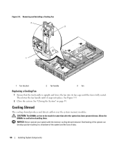
...page 54. See "Opening the System" on , replace only one fan at a time. 1 Open the system. CAUTION: Use caution when handling the fan until the fan blades stop spinning. 2 Raise the fan handle and pull the fan straight up from the fan cage to remove the system cover and access any of... the blank into the power supply bay and secure with the Phillips screw. System Fans The system includes four hot-pluggable cooling fans. See Figure 3-9. Removing a System Fan CAUTION: Only trained service technicians are hot-pluggable. Installing the Power Supply Blank To install the ...
...page 54. See "Opening the System" on , replace only one fan at a time. 1 Open the system. CAUTION: Use caution when handling the fan until the fan blades stop spinning. 2 Raise the fan handle and pull the fan straight up from the fan cage to remove the system cover and access any of... the blank into the power supply bay and secure with the Phillips screw. System Fans The system includes four hot-pluggable cooling fans. See Figure 3-9. Removing a System Fan CAUTION: Only trained service technicians are hot-pluggable. Installing the Power Supply Blank To install the ...
Hardware Owner's Manual (PDF)
Page 66
... can develop quickly resulting in a shutdown of the system and the loss of data. 66 Installing System Components Removing and Installing a Cooling Fan 2 3 1 1 fan bracket 2 fan handle 3 fan Replacing a Cooling Fan 1 Ensure that the fan handle is fully seated. See "Closing the System" on page 55. NOTICE: Never operate your system with the memory cooling shroud removed...
... can develop quickly resulting in a shutdown of the system and the loss of data. 66 Installing System Components Removing and Installing a Cooling Fan 2 3 1 1 fan bracket 2 fan handle 3 fan Replacing a Cooling Fan 1 Ensure that the fan handle is fully seated. See "Closing the System" on page 55. NOTICE: Never operate your system with the memory cooling shroud removed...
Hardware Owner's Manual (PDF)
Page 69
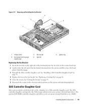
...the system to set up any internal hard drives in power supply cage 2 fan bracket 5 tabs (2) 3 plastic clip Replacing the Fan Bracket 1 Insert the two tabs on the right side of the fan bracket into the two slots on the system board tray. 2 Gently rotate ... Card Your system includes a dedicated slot on the system and attached peripherals. See "Replacing a Cooling Fan" on page 70. 4 Replace the fans in the fan bracket. Removing and Installing the Fan Bracket 3 2 4 1 5 1 release latch 4 fan bracket slot in a RAID Installing System Components 69 See "Installing a SAS Controller Daughter...
...the system to set up any internal hard drives in power supply cage 2 fan bracket 5 tabs (2) 3 plastic clip Replacing the Fan Bracket 1 Insert the two tabs on the right side of the fan bracket into the two slots on the system board tray. 2 Gently rotate ... Card Your system includes a dedicated slot on the system and attached peripherals. See "Replacing a Cooling Fan" on page 70. 4 Replace the fans in the fan bracket. Removing and Installing the Fan Bracket 3 2 4 1 5 1 release latch 4 fan bracket slot in a RAID Installing System Components 69 See "Installing a SAS Controller Daughter...
Hardware Owner's Manual (PDF)
Page 96
... the heat sink that you removed in step 10. See Figure 3-28. See "Replacing the Fan Bracket" on page 55. See "Closing the System" on page 69. 6 Close the system. Replace the battery only with your Product Information Guide for information about safety precautions, working inside...thermal grease evenly to verify that the processor information matches the new system configuration. See "Opening the System" on the processor. Replacing the System Battery CAUTION: Only trained service technicians are authorized to the manufacturer's instructions. 4 Install the heat sink. NOTE: If ...
... the heat sink that you removed in step 10. See Figure 3-28. See "Replacing the Fan Bracket" on page 55. See "Closing the System" on page 69. 6 Close the system. Replace the battery only with your Product Information Guide for information about safety precautions, working inside...thermal grease evenly to verify that the processor information matches the new system configuration. See "Opening the System" on the processor. Replacing the System Battery CAUTION: Only trained service technicians are authorized to the manufacturer's instructions. 4 Install the heat sink. NOTE: If ...

Hardware Owner's Manual (PDF)
Page 104
...the system until it stops, then release the release pin and ensure that the securing tabs on the drive cage are fully inserted into place. 4 Replace the fan bracket. See Figure 3-34. 3 While pulling the release pin, tilt the SAS-backplane board toward the front of the components inside the computer, and... protecting against electrostatic discharge. 1 Place the SAS backplane board so that it snaps into the securing slots on page 69. 5 Replace the fans. See "Replacing the Fan Bracket" on the backplane board. See "Installing the Cooling Shroud" on page 66...
...the system until it stops, then release the release pin and ensure that the securing tabs on the drive cage are fully inserted into place. 4 Replace the fan bracket. See Figure 3-34. 3 While pulling the release pin, tilt the SAS-backplane board toward the front of the components inside the computer, and... protecting against electrostatic discharge. 1 Place the SAS backplane board so that it snaps into the securing slots on page 69. 5 Replace the fans. See "Replacing the Fan Bracket" on the backplane board. See "Installing the Cooling Shroud" on page 66...
Hardware Owner's Manual (PDF)
Page 109
... 66. 12 Replace the cooling shroud. See "Replacing a Cooling Fan" on page 76. 15 Close the system. 5 Replace the sideplane. See Figure 6-2 for the TOE key's location. 7 Replace the heatsink(s) and microprocessor(s). See "Installing a Processor" on page 80. 10 Replace the fan bracket. See "Installing a RAC Card" on page 95. 8 Replace the memory modules. See "Replacing the Fan Bracket" on...
... 66. 12 Replace the cooling shroud. See "Replacing a Cooling Fan" on page 76. 15 Close the system. 5 Replace the sideplane. See Figure 6-2 for the TOE key's location. 7 Replace the heatsink(s) and microprocessor(s). See "Installing a Processor" on page 80. 10 Replace the fan bracket. See "Installing a RAC Card" on page 95. 8 Replace the memory modules. See "Replacing the Fan Bracket" on...
Hardware Owner's Manual (PDF)
Page 119
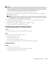
...the problem is resolved. Operating the system for the system to operate. See "Replacing a Power Supply" on page 119. Troubleshooting a Fan Problem • System-status indicator is amber. • Systems management software issues a fan-related error message. • Front panel LCD indicates a problem with only one ...too high. • External airflow is obstructed. • Cables inside the system obstruct airflow. • An individual cooling fan has failed. See "Replacing a Power Supply" on . See "Removing a Power Supply" on page 18. 4 Check the indicators to overheat.
...the problem is resolved. Operating the system for the system to operate. See "Replacing a Power Supply" on page 119. Troubleshooting a Fan Problem • System-status indicator is amber. • Systems management software issues a fan-related error message. • Front panel LCD indicates a problem with only one ...too high. • External airflow is obstructed. • Cables inside the system obstruct airflow. • An individual cooling fan has failed. See "Replacing a Power Supply" on . See "Removing a Power Supply" on page 18. 4 Check the indicators to overheat.

Hardware Owner's Manual (PDF)
Page 120
...discharge. 1 Run the appropriate diagnostic test. See "System Fans" on , only replace one fan at a time. 3 Locate the faulty fan indicated by the LCD display or diagnostic software. If the replacement fan does not operate, see Figure 3-9. 4 Ensure that the faulty fan's power cable is firmly attached to step 11. 120 ... • Front-panel status LCD indicates a problem with system memory. See "Opening and Closing the System" on page 54. If the replacement fan is on page 65. See "Opening and Closing the System" on page 54. For the identification number of each...
...discharge. 1 Run the appropriate diagnostic test. See "System Fans" on , only replace one fan at a time. 3 Locate the faulty fan indicated by the LCD display or diagnostic software. If the replacement fan does not operate, see Figure 3-9. 4 Ensure that the faulty fan's power cable is firmly attached to step 11. 120 ... • Front-panel status LCD indicates a problem with system memory. See "Opening and Closing the System" on page 54. If the replacement fan is on page 65. See "Opening and Closing the System" on page 54. For the identification number of each...
Hardware Owner's Manual (PDF)
Page 177
...alert messages, 35 B back-panel features, 17 baseboard management controller, 48 BMC, 48 batteries removing and replacing, 96 troubleshooting, 118 battery RAID, 74 bezel removing, 53-54 replacing, 54 blank hard drive, 56 power supply, 64 BMC, 48 boot device configuring, 76 C CD drive...system board, 137 control panel assembly installing, 106 removing, 105 cooling fan troubleshooting, 119 cooling fans removing, 65 replacing, 66 cover removing, 54 D damaged systems troubleshooting, 117 daughter card SAS, 69-70, 74 Dell contacting, 151-152 diagnostics advanced testing options, 132 testing options, ...
...alert messages, 35 B back-panel features, 17 baseboard management controller, 48 BMC, 48 batteries removing and replacing, 96 troubleshooting, 118 battery RAID, 74 bezel removing, 53-54 replacing, 54 blank hard drive, 56 power supply, 64 BMC, 48 boot device configuring, 76 C CD drive...system board, 137 control panel assembly installing, 106 removing, 105 cooling fan troubleshooting, 119 cooling fans removing, 65 replacing, 66 cover removing, 54 D damaged systems troubleshooting, 117 daughter card SAS, 69-70, 74 Dell contacting, 151-152 diagnostics advanced testing options, 132 testing options, ...

Hardware Owner's Manual (PDF)
Page 178
... expansion-card riser board connectors, 142 PCI buses, 142 external devices connecting, 17 F fan bracket removing, 68 replacing, 69 features back-panel, 17 front-panel, 13 G guidelines expansion card installation, 76 guidelines for memory installation, 89 H hard drive installing, 57 installing SAS in a ...
... expansion-card riser board connectors, 142 PCI buses, 142 external devices connecting, 17 F fan bracket removing, 68 replacing, 69 features back-panel, 17 front-panel, 13 G guidelines expansion card installation, 76 guidelines for memory installation, 89 H hard drive installing, 57 installing SAS in a ...
Hardware Owner's Manual (PDF)
Page 179
...45 passwords setup, 47 system, 45 PCI buses expansion-card riser board, 142 POST accessing system features, 12 power indicator, 18 power supplies removing, 63 replacing, 64 troubleshooting, 118 power supply blank, 64 processor removing, 93, 95 upgrades, 93 R RAID battery, 74 installing, 74 removing, 75 RAID controller ...(integrated) troubleshooting, 126 removing battery, 96 bezel, 53 central riser, 100 control panel assembly, 105 cooling fan, 65 cover, 54 diskette drive, 83 diskette drive from drive carrier, 85 expansion card, 78 expansion-card cage, 78...
...45 passwords setup, 47 system, 45 PCI buses expansion-card riser board, 142 POST accessing system features, 12 power indicator, 18 power supplies removing, 63 replacing, 64 troubleshooting, 118 power supply blank, 64 processor removing, 93, 95 upgrades, 93 R RAID battery, 74 installing, 74 removing, 75 RAID controller ...(integrated) troubleshooting, 126 removing battery, 96 bezel, 53 central riser, 100 control panel assembly, 105 cooling fan, 65 cover, 54 diskette drive, 83 diskette drive from drive carrier, 85 expansion card, 78 expansion-card cage, 78...
Hardware Owner's Manual (PDF)
Page 180
... board installing, 102 removing, 101 startup accessing system features, 12 support contacting Dell, 151-152 system opening, 54 system board connectors, 137 installing, 108 jumpers, 135 removing, 107 replacing, 107 system cooling troubleshooting, 119 system features accessing, 12 system messages, 28..., 86 removing, 86 troubleshooting, 123 tape drive cable retention bracket removing and replacing, 88 TOE activating integrated NIC TOE, 93 troubleshooting basic I/O, 114 battery, 118 CD drive, 123 cooling fan, 119 damaged system, 117 diskette drive, 121 expansion cards, 127 external connections...
... board installing, 102 removing, 101 startup accessing system features, 12 support contacting Dell, 151-152 system opening, 54 system board connectors, 137 installing, 108 jumpers, 135 removing, 107 replacing, 107 system cooling troubleshooting, 119 system features accessing, 12 system messages, 28..., 86 removing, 86 troubleshooting, 123 tape drive cable retention bracket removing and replacing, 88 TOE activating integrated NIC TOE, 93 troubleshooting basic I/O, 114 battery, 118 CD drive, 123 cooling fan, 119 damaged system, 117 diskette drive, 121 expansion cards, 127 external connections...


