
System Information Guide
Page 35
... (see the following section, "Dell Software and Peripherals (Canada Only)"). "Total Satisfaction" Return Policy (Canada Only) If you are a Government, Education, or Healthcare Customer, or an Individual Home Consumer who want to return, for a refund or credit of the manuals, floppy disk(s), CD(s), power ...cables, and other items included with any shipping and handling charges shown on your refund or credit, Dell expects you receive them to Dell up to Dell in the original shipment. For customers who ...
... (see the following section, "Dell Software and Peripherals (Canada Only)"). "Total Satisfaction" Return Policy (Canada Only) If you are a Government, Education, or Healthcare Customer, or an Individual Home Consumer who want to return, for a refund or credit of the manuals, floppy disk(s), CD(s), power ...cables, and other items included with any shipping and handling charges shown on your refund or credit, Dell expects you receive them to Dell up to Dell in the original shipment. For customers who ...
System Information Guide
Page 36
...condition), prepay shipping charges, and insure the shipment or accept the risk of loss or damage during shipment. www.dell.com | support.dell.com Dell Software and Peripherals (Canada Only) Third-Party Software and Peripherals Products Similar to other items included with a product ... or guarantee all of the manuals, floppy disk(s), CD(s), power cables, and other resellers of software and peripheral products, we recommend and encourage you must call Dell Customer Service at Dell's expense. To determine which limited warranty applies to Dell in materials, workmanship, and ...
...condition), prepay shipping charges, and insure the shipment or accept the risk of loss or damage during shipment. www.dell.com | support.dell.com Dell Software and Peripherals (Canada Only) Third-Party Software and Peripherals Products Similar to other items included with a product ... or guarantee all of the manuals, floppy disk(s), CD(s), power cables, and other resellers of software and peripheral products, we recommend and encourage you must call Dell Customer Service at Dell's expense. To determine which limited warranty applies to Dell in materials, workmanship, and ...
Service Manual
Page 1
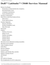
Dell Latitude C840 Service Manual Dell™ Latitude™ C840 Service Manual Before You Begin Preparing to Work Inside the Computer Recommended Tools Computer Orientation Screw Identification System Components Hard Drive and Fixed Optical Drive Hard Drive ... System Board Battery and Module Bay Latches Battery Charger Board LED Board Fan RJ-11/RJ-45 Module Pin Assignments for I/O Connectors file:///F|/Service%20Manuals/Dell/Latitude/c840/index.htm (1 of 2) [2/28/2004 8:03:26 AM]
Dell Latitude C840 Service Manual Dell™ Latitude™ C840 Service Manual Before You Begin Preparing to Work Inside the Computer Recommended Tools Computer Orientation Screw Identification System Components Hard Drive and Fixed Optical Drive Hard Drive ... System Board Battery and Module Bay Latches Battery Charger Board LED Board Fan RJ-11/RJ-45 Module Pin Assignments for I/O Connectors file:///F|/Service%20Manuals/Dell/Latitude/c840/index.htm (1 of 2) [2/28/2004 8:03:26 AM]
Service Manual
Page 2
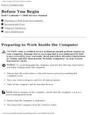
... safety instructions in "Safety and EMC Instructions: Portable Computers" in progress and exit all attached devices. Before You Begin: Dell Latitude C840 Service Manual Back to Contents Page Before You Begin Dell™ Latitude™ C840 Service Manual Preparing to Work Inside the Computer Recommended Tools Computer Orientation Screw Identification Preparing to Work Inside the Computer CAUTION: Only...
... safety instructions in "Safety and EMC Instructions: Portable Computers" in progress and exit all attached devices. Before You Begin: Dell Latitude C840 Service Manual Back to Contents Page Before You Begin Dell™ Latitude™ C840 Service Manual Preparing to Work Inside the Computer Recommended Tools Computer Orientation Screw Identification Preparing to Work Inside the Computer CAUTION: Only...
Service Manual
Page 3
... the PC Card slot. 9. Remove any installed batteries before you work surface. 10. Before You Begin: Dell Latitude C840 Service Manual 6. To avoid possible damage to the system board, wait 10 to upgrade the BIOS) file:///F|/Service%20Manuals/Dell/Latitude/c840/begin.htm (2 of 6) [2/28/2004 8:03:35 AM] Close the display and turn the computer upside...
... the PC Card slot. 9. Remove any installed batteries before you work surface. 10. Before You Begin: Dell Latitude C840 Service Manual 6. To avoid possible damage to the system board, wait 10 to upgrade the BIOS) file:///F|/Service%20Manuals/Dell/Latitude/c840/begin.htm (2 of 6) [2/28/2004 8:03:35 AM] Close the display and turn the computer upside...
Service Manual
Page 4
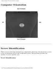
Screw Identification file:///F|/Service%20Manuals/Dell/Latitude/c840/begin.htm (3 of screws and the sizes. The placemat provides the number of 6) [2/28/2004 8:03:35 AM] Before You Begin: Dell Latitude C840 Service Manual Computer Orientation Screw Identification When you are removing and replacing components, photocopy the placemat as a tool to lay out and keep track of the component screws.
Screw Identification file:///F|/Service%20Manuals/Dell/Latitude/c840/begin.htm (3 of screws and the sizes. The placemat provides the number of 6) [2/28/2004 8:03:35 AM] Before You Begin: Dell Latitude C840 Service Manual Computer Orientation Screw Identification When you are removing and replacing components, photocopy the placemat as a tool to lay out and keep track of the component screws.
Service Manual
Page 5
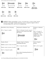
... (6 each) Flex-Cable Mounting Bracket to Bottom Case: M2.5 x 20 mm (4 each ) Keyboard to Top Cover: file:///F|/Service%20Manuals/Dell/Latitude/c840/begin.htm (4 of the correct diameter and length. Before You Begin: Dell Latitude C840 Service Manual NOTICE: When reinstalling a screw, you must use a screw of 6) [2/28/2004 8:03:35 AM] Ensure that the screw is...
... (6 each) Flex-Cable Mounting Bracket to Bottom Case: M2.5 x 20 mm (4 each ) Keyboard to Top Cover: file:///F|/Service%20Manuals/Dell/Latitude/c840/begin.htm (4 of the correct diameter and length. Before You Begin: Dell Latitude C840 Service Manual NOTICE: When reinstalling a screw, you must use a screw of 6) [2/28/2004 8:03:35 AM] Ensure that the screw is...
Service Manual
Page 6
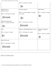
Before You Begin: Dell Latitude C840 Service Manual M2.5 x 4 mm (1 each) Palm Rest to Bottom Case: M2.5 x 20 mm (9 each) System Board: M2.5 x 4 mm captive washer (3 each) LED Board: M2 x 4 mm (2 each) Palm Rest Bracket: M2.5 x 4 mm (4 each) M2.5 x 20 mm (1 each) Fan: M2 x 4 mm (3 each) Memory Module/Modem Cover: M2.5 x 20 mm (1 each) Modem Daughter Card: M2 x 3 mm (1 each) Mini PCI Card: M2.5 x 20 mm (1 each) Back to Contents Page file:///F|/Service%20Manuals/Dell/Latitude/c840/begin.htm (5 of 6) [2/28/2004 8:03:35 AM]
Before You Begin: Dell Latitude C840 Service Manual M2.5 x 4 mm (1 each) Palm Rest to Bottom Case: M2.5 x 20 mm (9 each) System Board: M2.5 x 4 mm captive washer (3 each) LED Board: M2 x 4 mm (2 each) Palm Rest Bracket: M2.5 x 4 mm (4 each) M2.5 x 20 mm (1 each) Fan: M2 x 4 mm (3 each) Memory Module/Modem Cover: M2.5 x 20 mm (1 each) Modem Daughter Card: M2 x 3 mm (1 each) Mini PCI Card: M2.5 x 20 mm (1 each) Back to Contents Page file:///F|/Service%20Manuals/Dell/Latitude/c840/begin.htm (5 of 6) [2/28/2004 8:03:35 AM]
Service Manual
Page 8
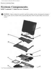
System Components: Dell Latitude C840 Service Manual Back to Contents Page System Components Dell™ Latitude™ C840 Service Manual NOTICE: Unless otherwise noted, each procedure in this document assumes that a part can be replaced by performing the removal procedure in reverse order. file:///F|/Service%20Manuals/Dell/Latitude/c840/system.htm (1 of 2) [2/28/2004 8:03:36 AM]
System Components: Dell Latitude C840 Service Manual Back to Contents Page System Components Dell™ Latitude™ C840 Service Manual NOTICE: Unless otherwise noted, each procedure in this document assumes that a part can be replaced by performing the removal procedure in reverse order. file:///F|/Service%20Manuals/Dell/Latitude/c840/system.htm (1 of 2) [2/28/2004 8:03:36 AM]
Service Manual
Page 9
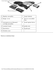
System Components: Dell Latitude C840 Service Manual 1 display assembly 2 hinge cover 3 microprocessor thermalcooling assembly 4 system board 5 hard drive 6 bottom case 7 main battery 8 device in module bay 9 fixed optical drive 10 palm rest 11 keyboard Back to Contents Page file:///F|/Service%20Manuals/Dell/Latitude/c840/system.htm (2 of 2) [2/28/2004 8:03:36 AM]
System Components: Dell Latitude C840 Service Manual 1 display assembly 2 hinge cover 3 microprocessor thermalcooling assembly 4 system board 5 hard drive 6 bottom case 7 main battery 8 device in module bay 9 fixed optical drive 10 palm rest 11 keyboard Back to Contents Page file:///F|/Service%20Manuals/Dell/Latitude/c840/system.htm (2 of 2) [2/28/2004 8:03:36 AM]
Service Manual
Page 10
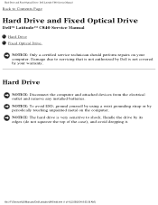
file:///F|/Service%20Manuals/Dell/Latitude/c840/hdd.htm (1 of the case), and avoid dropping it. Damage due to servicing that is not authorized by your computer. NOTICE: To avoid ESD, ground ... unpainted metal on your warranty. NOTICE: The hard drive is not covered by Dell is very sensitive to shock. Hard Drive and Fixed Optical Drive: Dell Latitude C840 Service Manual Back to Contents Page Hard Drive and Fixed Optical Drive Dell™ Latitude™ C840 Service Manual Hard Drive Fixed Optical Drive NOTICE: Only a certified service technician should perform...
file:///F|/Service%20Manuals/Dell/Latitude/c840/hdd.htm (1 of the case), and avoid dropping it. Damage due to servicing that is not authorized by your computer. NOTICE: To avoid ESD, ground ... unpainted metal on your warranty. NOTICE: The hard drive is not covered by Dell is very sensitive to shock. Hard Drive and Fixed Optical Drive: Dell Latitude C840 Service Manual Back to Contents Page Hard Drive and Fixed Optical Drive Dell™ Latitude™ C840 Service Manual Hard Drive Fixed Optical Drive NOTICE: Only a certified service technician should perform...
Service Manual
Page 11
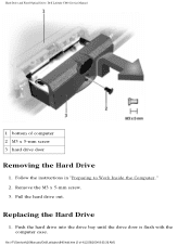
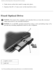
Remove the M3 x 5-mm screw. 3. file:///F|/Service%20Manuals/Dell/Latitude/c840/hdd.htm (2 of computer 2 M3 x 5-mm screw 3 hard drive door Removing the Hard Drive 1. Pull the hard drive out. Push the hard drive into the drive bay until the drive door is flush with the computer case. Hard Drive and Fixed Optical Drive: Dell Latitude C840 Service Manual 1 bottom of 4) [2/28/2004 8:03:36 AM] Replacing the Hard Drive 1. Follow the instructions in "Preparing to Work Inside the Computer." 2.
Remove the M3 x 5-mm screw. 3. file:///F|/Service%20Manuals/Dell/Latitude/c840/hdd.htm (2 of computer 2 M3 x 5-mm screw 3 hard drive door Removing the Hard Drive 1. Pull the hard drive out. Push the hard drive into the drive bay until the drive door is flush with the computer case. Hard Drive and Fixed Optical Drive: Dell Latitude C840 Service Manual 1 bottom of 4) [2/28/2004 8:03:36 AM] Replacing the Hard Drive 1. Follow the instructions in "Preparing to Work Inside the Computer." 2.
Service Manual
Page 12
Fixed Optical Drive NOTICE: Disconnect the computer and attached devices from the electrical outlet and remove any installed batteries. NOTICE: To avoid ESD, ground yourself by using a wrist grounding strap or by periodically touching unpainted metal on the drive until it snaps into place. 3. Hard Drive and Fixed Optical Drive: Dell Latitude C840 Service Manual 2. Push down on the computer. 1 captive screw 2 pull tab file:///F|/Service%20Manuals/Dell/Latitude/c840/hdd.htm (3 of 4) [2/28/2004 8:03:36 AM] Replace the M3 x 5-mm screw in the hard drive door.
Fixed Optical Drive NOTICE: Disconnect the computer and attached devices from the electrical outlet and remove any installed batteries. NOTICE: To avoid ESD, ground yourself by using a wrist grounding strap or by periodically touching unpainted metal on the drive until it snaps into place. 3. Hard Drive and Fixed Optical Drive: Dell Latitude C840 Service Manual 2. Push down on the computer. 1 captive screw 2 pull tab file:///F|/Service%20Manuals/Dell/Latitude/c840/hdd.htm (3 of 4) [2/28/2004 8:03:36 AM] Replace the M3 x 5-mm screw in the hard drive door.
Service Manual
Page 13
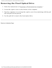
Hard Drive and Fixed Optical Drive: Dell Latitude C840 Service Manual Removing the Fixed Optical Drive 1. Turn the computer over (to remove the fixed optical drive. Loosen the captive screw on the bottom of 4) [2/28/2004 8:03:36 AM] Use the pull tab to keep the captive screw from interfering with the pull tab) and pull out the pull tab. 4. Back to Work Inside the Computer." 2. Follow the instructions in "Preparing to Contents Page file:///F|/Service%20Manuals/Dell/Latitude/c840/hdd.htm (4 of the computer. 3.
Hard Drive and Fixed Optical Drive: Dell Latitude C840 Service Manual Removing the Fixed Optical Drive 1. Turn the computer over (to remove the fixed optical drive. Loosen the captive screw on the bottom of 4) [2/28/2004 8:03:36 AM] Use the pull tab to keep the captive screw from interfering with the pull tab) and pull out the pull tab. 4. Back to Work Inside the Computer." 2. Follow the instructions in "Preparing to Contents Page file:///F|/Service%20Manuals/Dell/Latitude/c840/hdd.htm (4 of the computer. 3.
Service Manual
Page 14
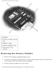
NOTICE: To avoid ESD, ground yourself by using a wrist grounding strap or by periodically touching unpainted metal on the computer. System Upgrades: Dell Latitude C840 Service Manual Back to Contents Page System Upgrades Dell™ Latitude™ C840 Service Manual Memory Modules Modem Daughter Card Mini PCI Card Memory Modules NOTICE: Disconnect the computer and any attached devices from electrical outlets and remove any installed batteries. Removing the Memory Module/Modem Cover file:///F|/Service%20Manuals/Dell/Latitude/c840/upgrades.htm (1 of 9) [2/28/2004 8:03:38 AM]
NOTICE: To avoid ESD, ground yourself by using a wrist grounding strap or by periodically touching unpainted metal on the computer. System Upgrades: Dell Latitude C840 Service Manual Back to Contents Page System Upgrades Dell™ Latitude™ C840 Service Manual Memory Modules Modem Daughter Card Mini PCI Card Memory Modules NOTICE: Disconnect the computer and any attached devices from electrical outlets and remove any installed batteries. Removing the Memory Module/Modem Cover file:///F|/Service%20Manuals/Dell/Latitude/c840/upgrades.htm (1 of 9) [2/28/2004 8:03:38 AM]
Service Manual
Page 15
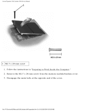
Remove the M2.5 x 20-mm screw from the memory module/modem cover. 3. file:///F|/Service%20Manuals/Dell/Latitude/c840/upgrades.htm (2 of the cover. Disengage the metal tabs at the opposite end of 9) [2/28/2004 8:03:38 AM] Follow the instructions in "Preparing to Work Inside the Computer." 2. System Upgrades: Dell Latitude C840 Service Manual 1 M2.5 x 20-mm screw 1.
Remove the M2.5 x 20-mm screw from the memory module/modem cover. 3. file:///F|/Service%20Manuals/Dell/Latitude/c840/upgrades.htm (2 of the cover. Disengage the metal tabs at the opposite end of 9) [2/28/2004 8:03:38 AM] Follow the instructions in "Preparing to Work Inside the Computer." 2. System Upgrades: Dell Latitude C840 Service Manual 1 M2.5 x 20-mm screw 1.
Service Manual
Page 16
To release a memory module from its socket. Lift the memory module out of its socket, spread apart the tabs at each side of 9) [2/28/2004 8:03:38 AM] Remove the memory module/modem cover. 2. file:///F|/Service%20Manuals/Dell/Latitude/c840/upgrades.htm (3 of the module until the module pops up slightly. 3. System Upgrades: Dell Latitude C840 Service Manual 1 DIMM B 2 memory module sockets (2) 3 DIMM A socket 4 modem daughter card 5 metal tabs (2 per socket) Removing the Memory Modules 1.
To release a memory module from its socket. Lift the memory module out of its socket, spread apart the tabs at each side of 9) [2/28/2004 8:03:38 AM] Remove the memory module/modem cover. 2. file:///F|/Service%20Manuals/Dell/Latitude/c840/upgrades.htm (3 of the module until the module pops up slightly. 3. System Upgrades: Dell Latitude C840 Service Manual 1 DIMM B 2 memory module sockets (2) 3 DIMM A socket 4 modem daughter card 5 metal tabs (2 per socket) Removing the Memory Modules 1.
Service Manual
Page 17
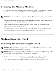
... periodically touching unpainted metal on the memory module/modem cover into the bottom case, rotate the cover down until it clicks into place. System Upgrades: Dell Latitude C840 Service Manual Replacing the Memory Modules 1. Follow the instructions in only one memory module, install it . 4. Install a second memory module in the socket labeled "DIMM ...click, remove the module and reinstall it in the socket labeled "DIMM B." NOTE: Memory modules are keyed to Work Inside the Computer." 2. file:///F|/Service%20Manuals/Dell/Latitude/c840/upgrades.htm (4 of 9) [2/28/2004 8:03:38 AM]
... periodically touching unpainted metal on the memory module/modem cover into the bottom case, rotate the cover down until it clicks into place. System Upgrades: Dell Latitude C840 Service Manual Replacing the Memory Modules 1. Follow the instructions in only one memory module, install it . 4. Install a second memory module in the socket labeled "DIMM ...click, remove the module and reinstall it in the socket labeled "DIMM B." NOTE: Memory modules are keyed to Work Inside the Computer." 2. file:///F|/Service%20Manuals/Dell/Latitude/c840/upgrades.htm (4 of 9) [2/28/2004 8:03:38 AM]
Service Manual
Page 18
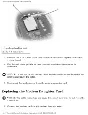
... (5 of its connector. Pull the connector on the modem cable. Use the pull tab to disconnect the cable. 5. Do not force the connections. 1. System Upgrades: Dell Latitude C840 Service Manual 1 modem daughter card 2 M2 x 3-mm screw 3. Replacing the Modem Daughter Card NOTICE: The cable connectors are keyed for correct insertion. Disconnect the modem cable...
... (5 of its connector. Pull the connector on the modem cable. Use the pull tab to disconnect the cable. 5. Do not force the connections. 1. System Upgrades: Dell Latitude C840 Service Manual 1 modem daughter card 2 M2 x 3-mm screw 3. Replacing the Modem Daughter Card NOTICE: The cable connectors are keyed for correct insertion. Disconnect the modem cable...
Service Manual
Page 19
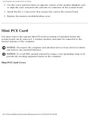
Mini PCI Card Cover file:///F|/Service%20Manuals/Dell/Latitude/c840/upgrades.htm (6 of the modem daughter card to align the card, and press the card into its connector on the computer. Mini PCI Card You ... of 9) [2/28/2004 8:03:38 AM] Install the M2 x 3-mm screw that secures the card to the internal antenna of the computer. System Upgrades: Dell Latitude C840 Service Manual 2. NOTICE: Disconnect the computer and attached devices from electrical outlets and remove any installed batteries. A wireless modem card must remove the optional Mini PCI wireless...
Mini PCI Card Cover file:///F|/Service%20Manuals/Dell/Latitude/c840/upgrades.htm (6 of the modem daughter card to align the card, and press the card into its connector on the computer. Mini PCI Card You ... of 9) [2/28/2004 8:03:38 AM] Install the M2 x 3-mm screw that secures the card to the internal antenna of the computer. System Upgrades: Dell Latitude C840 Service Manual 2. NOTICE: Disconnect the computer and attached devices from electrical outlets and remove any installed batteries. A wireless modem card must remove the optional Mini PCI wireless...


