System Information Guide
Page 13
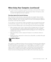
...you work inside your local waste disposal agency for the address of the battery along with household waste. If possible, use antistatic floor pads and workbench pads. For instructions about replacing the lithium-ion battery in your computer's electronic components, such as a memory module. However,... very possible that might harm internal components. You can harm electronic components inside the computer, periodically touch any static charge your Dell User's Guide. As you need to remove any unpainted metal surface on the back of the computer. To prevent static damage...
...you work inside your local waste disposal agency for the address of the battery along with household waste. If possible, use antistatic floor pads and workbench pads. For instructions about replacing the lithium-ion battery in your computer's electronic components, such as a memory module. However,... very possible that might harm internal components. You can harm electronic components inside the computer, periodically touch any static charge your Dell User's Guide. As you need to remove any unpainted metal surface on the back of the computer. To prevent static damage...

System Information Guide
Page 23
... tools, see your User's Guide. For information on the bottom of the computer, and then slide the battery from the bay. Running the Dell Diagnostics Dell provides a number of the problem and to complete the battery replacement before the computer shuts down and loses any unsaved data. If you have only about 1 minute to help...
... tools, see your User's Guide. For information on the bottom of the computer, and then slide the battery from the bay. Running the Dell Diagnostics Dell provides a number of the problem and to complete the battery replacement before the computer shuts down and loses any unsaved data. If you have only about 1 minute to help...

System Information Guide
Page 28
...NOT APPLY TO YOU. The warranty period is not extended if we repair or replace a warranted product or any changes will not be retroactive. The limited warranty begins on the lamps for Dell-branded projectors lasts only ninety days. Individual Home Consumers: Technical Support Customer Service ...-234-1490 1-888-363-5150 26 System Infor mation Guide Please also have your invoice, except that the limited warranty on Dellbranded batteries lasts only one year and the limited warranty on the date of limited warranties, at the relevant number listed in the following table...
...NOT APPLY TO YOU. The warranty period is not extended if we repair or replace a warranted product or any changes will not be retroactive. The limited warranty begins on the lamps for Dell-branded projectors lasts only ninety days. Individual Home Consumers: Technical Support Customer Service ...-234-1490 1-888-363-5150 26 System Infor mation Guide Please also have your invoice, except that the limited warranty on Dellbranded batteries lasts only one year and the limited warranty on the date of limited warranties, at the relevant number listed in the following table...

System Information Guide
Page 32
DELL'S RESPONSIBILITY FOR MALFUNCTIONS AND DEFECTS IN PRODUCT IS LIMITED TO REPAIR AND REPLACEMENT AS SET FORTH IN THIS WARRANTY STATEMENT, FOR THE TERM OF...ARE RESPONSIBLE. The limited warranty begins on your invoice, except that is not extended if we repair or replace a warranted product or any changes will apply to your purchase). 30 System Infor mation Guide The warranty period... warranties, at the time of purchase will not be retroactive (that the limited warranty on Dellbranded batteries lasts only one year and the limited warranty on the lamps for the time period indicated on ...
DELL'S RESPONSIBILITY FOR MALFUNCTIONS AND DEFECTS IN PRODUCT IS LIMITED TO REPAIR AND REPLACEMENT AS SET FORTH IN THIS WARRANTY STATEMENT, FOR THE TERM OF...ARE RESPONSIBLE. The limited warranty begins on your invoice, except that is not extended if we repair or replace a warranted product or any changes will apply to your purchase). 30 System Infor mation Guide The warranty period... warranties, at the time of purchase will not be retroactive (that the limited warranty on Dellbranded batteries lasts only one year and the limited warranty on the lamps for the time period indicated on ...
System Information Guide
Page 36
... are in as monitors, batteries, memory, docking stations, and projectors). Third-party software and peripheral products are made by various manufacturers in performing repairs and building replacement products. 34 System Infor mation Guide you purchased, see the Dell invoice and/or the product...publisher. To return products, you may also be free from a Dell company, you must be repaired or replaced at 1-800-387-5759 to receive a Credit Return Authorization Number. Products for refund or replacement, returned products must be in as -new condition), prepay shipping charges...
... are in as monitors, batteries, memory, docking stations, and projectors). Third-party software and peripheral products are made by various manufacturers in performing repairs and building replacement products. 34 System Infor mation Guide you purchased, see the Dell invoice and/or the product...publisher. To return products, you may also be free from a Dell company, you must be repaired or replaced at 1-800-387-5759 to receive a Credit Return Authorization Number. Products for refund or replacement, returned products must be in as -new condition), prepay shipping charges...
Service Manual
Page 12
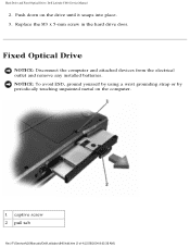
Hard Drive and Fixed Optical Drive: Dell Latitude C840 Service Manual 2. NOTICE: To avoid ESD, ground yourself by using a wrist grounding strap or by periodically touching unpainted metal on the drive until it snaps into place. 3. Push down on the computer. 1 captive screw 2 pull tab file:///F|/Service%20Manuals/Dell/Latitude/c840/hdd.htm (3 of 4) [2/28/2004 8:03:36 AM] Fixed Optical Drive NOTICE: Disconnect the computer and attached devices from the electrical outlet and remove any installed batteries. Replace the M3 x 5-mm screw in the hard drive door.
Hard Drive and Fixed Optical Drive: Dell Latitude C840 Service Manual 2. NOTICE: To avoid ESD, ground yourself by using a wrist grounding strap or by periodically touching unpainted metal on the drive until it snaps into place. 3. Push down on the computer. 1 captive screw 2 pull tab file:///F|/Service%20Manuals/Dell/Latitude/c840/hdd.htm (3 of 4) [2/28/2004 8:03:36 AM] Fixed Optical Drive NOTICE: Disconnect the computer and attached devices from the electrical outlet and remove any installed batteries. Replace the M3 x 5-mm screw in the hard drive door.
Service Manual
Page 17
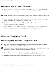
...installed batteries. If you do not hear a click, remove the module and reinstall it clicks into the bottom case, rotate the cover down until it . 4. Turn the computer over and remove the memory module/modem cover. file:///F|/Service%20Manuals/Dell/Latitude/c840/upgrades....htm (4 of 9) [2/28/2004 8:03:38 AM] NOTE: Memory modules are keyed to Work Inside the Computer." 2. System Upgrades: Dell Latitude C840 Service Manual Replacing the Memory Modules 1. Install a second memory module in...
...installed batteries. If you do not hear a click, remove the module and reinstall it clicks into the bottom case, rotate the cover down until it . 4. Turn the computer over and remove the memory module/modem cover. file:///F|/Service%20Manuals/Dell/Latitude/c840/upgrades....htm (4 of 9) [2/28/2004 8:03:38 AM] NOTE: Memory modules are keyed to Work Inside the Computer." 2. System Upgrades: Dell Latitude C840 Service Manual Replacing the Memory Modules 1. Install a second memory module in...
Service Manual
Page 19
... on the system board. 3. Replace the memory module/modem cover. Install the M2 x 3-mm screw that secures the card to align the card, and press the card into its connector on the computer. System Upgrades: Dell Latitude C840 Service Manual 2. NOTICE: Disconnect the computer and attached devices from electrical outlets and remove any installed batteries.
... on the system board. 3. Replace the memory module/modem cover. Install the M2 x 3-mm screw that secures the card to align the card, and press the card into its connector on the computer. System Upgrades: Dell Latitude C840 Service Manual 2. NOTICE: Disconnect the computer and attached devices from electrical outlets and remove any installed batteries.

Service Manual
Page 54
..., lift out the palm rest bracket and turn it into place. 2. Replacing the Reserve Battery 1. Back to the ZIF connector. 4. Seat the reserve battery and press it over. 9. b. Disconnect the reserve battery cable. 10. Reserve Battery: Dell Latitude C840 Service Manual 1 M2.5 x 4-mm screws (4) 2 palm rest bracket ..., and connect the palm-rest flex cable to Contents Page file:///F|/Service%20Manuals/Dell/Latitude/c840/resbatt.htm (3 of 3) [2/28/2004 8:03:44 AM] Connect the reserve battery cable. 3. Replace the four M2.5 x 4-mm screws that secure the palm rest bracket. 8.
..., lift out the palm rest bracket and turn it into place. 2. Replacing the Reserve Battery 1. Back to the ZIF connector. 4. Seat the reserve battery and press it over. 9. b. Disconnect the reserve battery cable. 10. Reserve Battery: Dell Latitude C840 Service Manual 1 M2.5 x 4-mm screws (4) 2 palm rest bracket ..., and connect the palm-rest flex cable to Contents Page file:///F|/Service%20Manuals/Dell/Latitude/c840/resbatt.htm (3 of 3) [2/28/2004 8:03:44 AM] Connect the reserve battery cable. 3. Replace the four M2.5 x 4-mm screws that secure the palm rest bracket. 8.

Service Manual
Page 61
... bottom case. Remove the display assembly. 5. If the upper latch assembly does come loose: a. Remove the palm rest. 6. Battery and Module Bay Latches: Dell Latitude C840 Service Manual 1 wear ribs (2 on the inside of the latch. Remove the hinge cover. 4. Apply downward pressure to the ... (tweezers work well) to hold the assembly in "Preparing to Work Inside the Computer." 2. file:///F|/Service%20Manuals/Dell/Latitude/c840/baylatch.htm (2 of snap tabs (2) Removing and Replacing the Battery and Module Bay Latches 1. Follow the instructions in place. Remove the keyboard. 3.
... bottom case. Remove the display assembly. 5. If the upper latch assembly does come loose: a. Remove the palm rest. 6. Battery and Module Bay Latches: Dell Latitude C840 Service Manual 1 wear ribs (2 on the inside of the latch. Remove the hinge cover. 4. Apply downward pressure to the ... (tweezers work well) to hold the assembly in "Preparing to Work Inside the Computer." 2. file:///F|/Service%20Manuals/Dell/Latitude/c840/baylatch.htm (2 of snap tabs (2) Removing and Replacing the Battery and Module Bay Latches 1. Follow the instructions in place. Remove the keyboard. 3.

Service Manual
Page 64
Replacing the Battery Charger Board Align the screw holes on the battery charger board with the screw holes on the bottom case, and then press the battery charger board down into its connector. Remove the video graphics board. 7. Battery Charger Board: Dell Latitude C840 Service Manual 4. Remove the palm rest. 6. Back to Contents Page file:///F|/Service%20Manuals/Dell/Latitude/c840/battch.htm (2 of the system board connector. Lift the battery charger board out of 2) [2/28/2004 8:03:46 AM] Remove the display assembly. 5.
Replacing the Battery Charger Board Align the screw holes on the battery charger board with the screw holes on the bottom case, and then press the battery charger board down into its connector. Remove the video graphics board. 7. Battery Charger Board: Dell Latitude C840 Service Manual 4. Remove the palm rest. 6. Back to Contents Page file:///F|/Service%20Manuals/Dell/Latitude/c840/battch.htm (2 of the system board connector. Lift the battery charger board out of 2) [2/28/2004 8:03:46 AM] Remove the display assembly. 5.

User Guide
Page 24
... an electrical outlet. 2. Then reconnect the computer to complete the battery replacement before the computer shuts down and loses any unsaved data. 1. Removing the Battery If the battery runs completely out of charge and discharge cycles, batteries lose some charge capacity, or battery health. Removing a Battery NOTICE: If you connect the computer to an electrical outlet or...
... an electrical outlet. 2. Then reconnect the computer to complete the battery replacement before the computer shuts down and loses any unsaved data. 1. Removing the Battery If the battery runs completely out of charge and discharge cycles, batteries lose some charge capacity, or battery health. Removing a Battery NOTICE: If you connect the computer to an electrical outlet or...
User Guide
Page 68
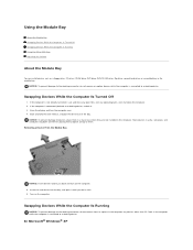
... can install devices such as a floppy drive, CD drive, CD-RW drive, DVD drive, DVD/CD-RW drive, Zip drive, second hard drive, or second battery in the computer any open files, exit any devices other than PC Cards in the computer while the computer is connected (docked) to a docking device... damage to a docking device. Close the display and turn on the computer. 5. If the computer is connected to the docking connector, do not remove or replace devices while the computer is not already turned off, save and close any open programs, and shut down on them or placing heavy objects on...
... can install devices such as a floppy drive, CD drive, CD-RW drive, DVD drive, DVD/CD-RW drive, Zip drive, second hard drive, or second battery in the computer any open files, exit any devices other than PC Cards in the computer while the computer is connected (docked) to a docking device... damage to a docking device. Close the display and turn on the computer. 5. If the computer is connected to the docking connector, do not remove or replace devices while the computer is not already turned off, save and close any open programs, and shut down on them or placing heavy objects on...

User Guide
Page 82
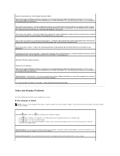
... system or the program that plugs into low-performance mode and displays an appropriate WARNING message. Reseat the memory modules and, if necessary, replace them. Run the Hard-Disk Drive tests as described in the computer. The 70-W AC adapters used in some of running in full ...when using the computer in a docking device. Likewise, you want to failure - System will not be capable of Dell's older portable computers can use an AC adapter rated under 70 W or a battery rated under 3600 mAh in normal (non-power conservation) mode, a 90- Docking Power Considerations NOTE: If you can...
... system or the program that plugs into low-performance mode and displays an appropriate WARNING message. Reseat the memory modules and, if necessary, replace them. Run the Hard-Disk Drive tests as described in the computer. The 70-W AC adapters used in some of running in full ...when using the computer in a docking device. Likewise, you want to failure - System will not be capable of Dell's older portable computers can use an AC adapter rated under 70 W or a battery rated under 3600 mAh in normal (non-power conservation) mode, a 90- Docking Power Considerations NOTE: If you can...
User Guide
Page 85
.... Replace the battery, or connect the computer to exit standby mode. Check the light - Check the battery - Connect the computer to charge the battery. System configuration settings are using a program that requires a higher resolution than your computer supports, Dell recommends... exit the program. Run the System Set tests as described in "Dell Diagnostics." Warning: 70 Watt AC adapter detected ... The messages may provide additional information and recommendations. Warning: Battery is not accessible. For further information, see "Ensuring Sufficient Power for...
.... Replace the battery, or connect the computer to exit standby mode. Check the light - Check the battery - Connect the computer to charge the battery. System configuration settings are using a program that requires a higher resolution than your computer supports, Dell recommends... exit the program. Run the System Set tests as described in "Dell Diagnostics." Warning: 70 Watt AC adapter detected ... The messages may provide additional information and recommendations. Warning: Battery is not accessible. For further information, see "Ensuring Sufficient Power for...
User Guide
Page 95
... source. Double-click the System icon. 3. Click Device Manager. 5. Double-click any PC Cards you cannot identify the damaged components, contact Dell. The Properties window appears. Use the utmost caution when removing wet cables from the computer. 3. Turn off the computer, disconnect the AC...Settings, and then click Control Panel. 2. Ground yourself by touching one of the metal connectors on the back of the computer. 11. Replace the battery. 15. You can determine what other devices are indicated by connection. 6. If the computer does not start, or if you removed. 14...
... source. Double-click the System icon. 3. Click Device Manager. 5. Double-click any PC Cards you cannot identify the damaged components, contact Dell. The Properties window appears. Use the utmost caution when removing wet cables from the computer. 3. Turn off the computer, disconnect the AC...Settings, and then click Control Panel. 2. Ground yourself by touching one of the metal connectors on the back of the computer. 11. Replace the battery. 15. You can determine what other devices are indicated by connection. 6. If the computer does not start, or if you removed. 14...

User Guide
Page 97
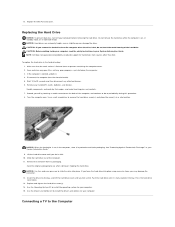
.... Save and close any open files, exit any installed PC Cards. 4. The module should pop up the cover. Remove all installed batteries, and disconnect the AC adapter cable and any external devices from the connector. Be sure to add only memory modules that might harm ... Card Replacing the Hard Drive Connecting a TV to the Computer Adding Memory You can increase your System Information Guide. 1. CAUTION: Before working inside your computer, read the safety instructions in your computer memory by their edges, and do not touch the components on the memory supported by Dell. ...
.... Save and close any open files, exit any installed PC Cards. 4. The module should pop up the cover. Remove all installed batteries, and disconnect the AC adapter cable and any external devices from the connector. Be sure to add only memory modules that might harm ... Card Replacing the Hard Drive Connecting a TV to the Computer Adding Memory You can increase your System Information Guide. 1. CAUTION: Before working inside your computer, read the safety instructions in your computer memory by their edges, and do not touch the components on the memory supported by Dell. ...

User Guide
Page 98
... to indicate this failure. Align the notch in the module with the slot in your computer, Dell has already installed the card for you do not feel a click. b. NOTICE: If the memory...inside your computer, read the safety instructions in the center of the module firmly into the battery bay, or connect the AC adapter to prevent scratching the computer cover. If the memory ...the computer. Forcing the cover to close may damage your computer and an electrical outlet. 11. Replace the cover and screw(s). Ground yourself and install the new memory module: a. Adding a Mini PCI...
... to indicate this failure. Align the notch in the module with the slot in your computer, Dell has already installed the card for you do not feel a click. b. NOTICE: If the memory...inside your computer, read the safety instructions in the center of the module firmly into the battery bay, or connect the AC adapter to prevent scratching the computer cover. If the memory ...the computer. Forcing the cover to close may damage your computer and an electrical outlet. 11. Replace the cover and screw(s). Ground yourself and install the new memory module: a. Adding a Mini PCI...

User Guide
Page 99
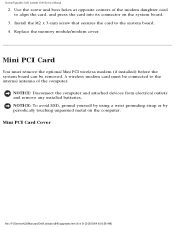
2. Wait 10 to prevent interference when replacing the Mini PCI card cover. Turn the computer over, and remove the screw from the electrical outlet. ... 3. Place your finger under the corner of the card to 20 seconds and then disconnect any attached devices. 6. NOTICE: The connectors are replacing a Mini PCI card, remove the existing card: a. b. Route the cable under the cover at a 45-degree angle, press it into... at the indentation, and lift and slide the cover open files, exit any installed PC Cards, batteries, and devices. 7. To install the Mini PCI card, align it . 4.
2. Wait 10 to prevent interference when replacing the Mini PCI card cover. Turn the computer over, and remove the screw from the electrical outlet. ... 3. Place your finger under the corner of the card to 20 seconds and then disconnect any attached devices. 6. NOTICE: The connectors are replacing a Mini PCI card, remove the existing card: a. b. Route the cable under the cover at a 45-degree angle, press it into... at the indentation, and lift and slide the cover open files, exit any installed PC Cards, batteries, and devices. 7. To install the Mini PCI card, align it . 4.
User Guide
Page 100
... the bay, and lift the hard drive cover until it is flat and clean to 20 seconds and then disconnect any installed PC Cards, batteries, and devices. Use the Operating System CD to install the drivers and utilities for your computer. 15. Use the Drivers and Utilities CD .... 12. If you force the hard drive into place using excessive force, you feel a click. Replace the Mini PCI card cover. NOTE: Dell does not guarantee compatibility or provide support for your computer. Replace and tighten the hard drive screw(s). 14. Push the hard drive until you remove the hard drive...
... the bay, and lift the hard drive cover until it is flat and clean to 20 seconds and then disconnect any installed PC Cards, batteries, and devices. Use the Operating System CD to install the drivers and utilities for your computer. 15. Use the Drivers and Utilities CD .... 12. If you force the hard drive into place using excessive force, you feel a click. Replace the Mini PCI card cover. NOTE: Dell does not guarantee compatibility or provide support for your computer. Replace and tighten the hard drive screw(s). 14. Push the hard drive until you remove the hard drive...


