System Information Guide
Page 12
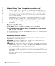
Ergonomic Computing Habits CAUTION: Improper or prolonged keyboard use a commercial window cleaner to reduce the potential for the appropriate contact... when you confirm that your computer and devices from the display quickly and keep the display dry. www.dell.com | support.dell.com When Using Your Computer (continued) • Clean the display with a soft, clean cloth and ... your User's Guide when setting up and using your computer gets wet or is not operating properly, contact Dell (see the User's Guide for personal injury or shock. Longterm exposure to the cloth; Do not use ...
Ergonomic Computing Habits CAUTION: Improper or prolonged keyboard use a commercial window cleaner to reduce the potential for the appropriate contact... when you confirm that your computer and devices from the display quickly and keep the display dry. www.dell.com | support.dell.com When Using Your Computer (continued) • Clean the display with a soft, clean cloth and ... your User's Guide when setting up and using your computer gets wet or is not operating properly, contact Dell (see the User's Guide for personal injury or shock. Longterm exposure to the cloth; Do not use ...
System Information Guide
Page 19
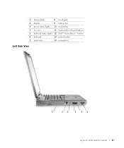
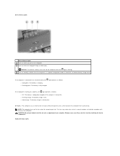
1 display latch 8 touch pad 2 display 9 battery bay 3 device status lights 10 module bay 4 air vent 11 track stick/touch pad buttons 5 keyboard status lights 12 Dell™ AccessDirect™ button 6 keyboard 13 power button 7 track stick 14 microphone Left Side View 1 23 4 56 System Infor mation Guide 17
1 display latch 8 touch pad 2 display 9 battery bay 3 device status lights 10 module bay 4 air vent 11 track stick/touch pad buttons 5 keyboard status lights 12 Dell™ AccessDirect™ button 6 keyboard 13 power button 7 track stick 14 microphone Left Side View 1 23 4 56 System Infor mation Guide 17
Service Manual
Page 1
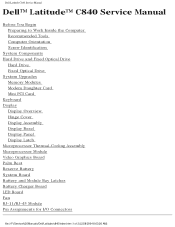
Dell Latitude C840 Service Manual Dell™ Latitude™ C840 Service Manual Before You Begin Preparing to Work Inside the Computer Recommended Tools Computer Orientation Screw Identification System Components Hard Drive and Fixed Optical Drive Hard Drive Fixed Optical Drive System Upgrades Memory Modules Modem Daughter Card Mini PCI Card Keyboard Display Display Overview Hinge ...Battery and Module Bay Latches Battery Charger Board LED Board Fan RJ-11/RJ-45 Module Pin Assignments for I/O Connectors file:///F|/Service%20Manuals/Dell/Latitude/c840/index.htm (1 of 2) [2/28/2004 8:03:26 AM]
Dell Latitude C840 Service Manual Dell™ Latitude™ C840 Service Manual Before You Begin Preparing to Work Inside the Computer Recommended Tools Computer Orientation Screw Identification System Components Hard Drive and Fixed Optical Drive Hard Drive Fixed Optical Drive System Upgrades Memory Modules Modem Daughter Card Mini PCI Card Keyboard Display Display Overview Hinge ...Battery and Module Bay Latches Battery Charger Board LED Board Fan RJ-11/RJ-45 Module Pin Assignments for I/O Connectors file:///F|/Service%20Manuals/Dell/Latitude/c840/index.htm (1 of 2) [2/28/2004 8:03:26 AM]
Service Manual
Page 5
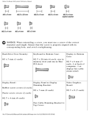
...: M2.5 x 8 (3 each) M2.5 x 4 mm (6 each) Flex-Cable Mounting Bracket to Bottom Case: M2.5 x 20 mm (4 each ) Keyboard to Top Cover: file:///F|/Service%20Manuals/Dell/Latitude/c840/begin.htm (4 of the correct diameter and length. Before You Begin: Dell Latitude C840 Service Manual NOTICE: When reinstalling a screw, you must use a screw of 6) [2/28/2004 8:03:35 AM] Hard...
...: M2.5 x 8 (3 each) M2.5 x 4 mm (6 each) Flex-Cable Mounting Bracket to Bottom Case: M2.5 x 20 mm (4 each ) Keyboard to Top Cover: file:///F|/Service%20Manuals/Dell/Latitude/c840/begin.htm (4 of the correct diameter and length. Before You Begin: Dell Latitude C840 Service Manual NOTICE: When reinstalling a screw, you must use a screw of 6) [2/28/2004 8:03:35 AM] Hard...
Service Manual
Page 9
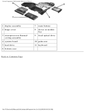
System Components: Dell Latitude C840 Service Manual 1 display assembly 2 hinge cover 3 microprocessor thermalcooling assembly 4 system board 5 hard drive 6 bottom case 7 main battery 8 device in module bay 9 fixed optical drive 10 palm rest 11 keyboard Back to Contents Page file:///F|/Service%20Manuals/Dell/Latitude/c840/system.htm (2 of 2) [2/28/2004 8:03:36 AM]
System Components: Dell Latitude C840 Service Manual 1 display assembly 2 hinge cover 3 microprocessor thermalcooling assembly 4 system board 5 hard drive 6 bottom case 7 main battery 8 device in module bay 9 fixed optical drive 10 palm rest 11 keyboard Back to Contents Page file:///F|/Service%20Manuals/Dell/Latitude/c840/system.htm (2 of 2) [2/28/2004 8:03:36 AM]
Service Manual
Page 23
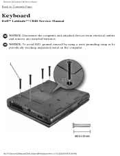
Keyboard: Dell Latitude C840 Service Manual Back to Contents Page Keyboard Dell™ Latitude™ C840 Service Manual NOTICE: Disconnect the computer and attached devices from electrical outlets and remove any installed batteries. NOTICE: To avoid ESD, ground yourself by using a wrist grounding strap or by periodically touching unpainted metal on the computer. file:///F|/Service%20Manuals/Dell/Latitude/c840/keyboard.htm (1 of 5) [2/28/2004 8:03:39 AM]
Keyboard: Dell Latitude C840 Service Manual Back to Contents Page Keyboard Dell™ Latitude™ C840 Service Manual NOTICE: Disconnect the computer and attached devices from electrical outlets and remove any installed batteries. NOTICE: To avoid ESD, ground yourself by using a wrist grounding strap or by periodically touching unpainted metal on the computer. file:///F|/Service%20Manuals/Dell/Latitude/c840/keyboard.htm (1 of 5) [2/28/2004 8:03:39 AM]
Service Manual
Page 24
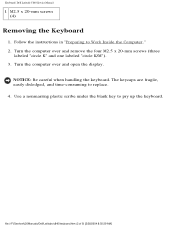
... four M2.5 x 20-mm screws (three labeled "circle K" and one labeled "circle K/M"). 3. file:///F|/Service%20Manuals/Dell/Latitude/c840/keyboard.htm (2 of 5) [2/28/2004 8:03:39 AM] Keyboard: Dell Latitude C840 Service Manual 1 M2.5 x 20-mm screws (4) Removing the Keyboard 1. Use a nonmarring plastic scribe under the blank key to pry up the keyboard. Turn the computer over and open the display.
... four M2.5 x 20-mm screws (three labeled "circle K" and one labeled "circle K/M"). 3. file:///F|/Service%20Manuals/Dell/Latitude/c840/keyboard.htm (2 of 5) [2/28/2004 8:03:39 AM] Keyboard: Dell Latitude C840 Service Manual 1 M2.5 x 20-mm screws (4) Removing the Keyboard 1. Use a nonmarring plastic scribe under the blank key to pry up the keyboard. Turn the computer over and open the display.
Service Manual
Page 25
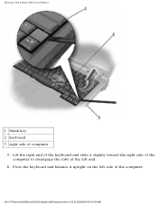
file:///F|/Service%20Manuals/Dell/Latitude/c840/keyboard.htm (3 of computer 5. Lift the right end of the computer. Pivot the keyboard and balance it slightly toward the right side of the computer to disengage the tabs at the left side of the keyboard and slide it upright on the left end. 6. Keyboard: Dell Latitude C840 Service Manual 1 blank key 2 keyboard 3 right side of 5) [2/28/2004 8:03:39 AM]
file:///F|/Service%20Manuals/Dell/Latitude/c840/keyboard.htm (3 of computer 5. Lift the right end of the computer. Pivot the keyboard and balance it slightly toward the right side of the computer to disengage the tabs at the left side of the keyboard and slide it upright on the left end. 6. Keyboard: Dell Latitude C840 Service Manual 1 blank key 2 keyboard 3 right side of 5) [2/28/2004 8:03:39 AM]

Service Manual
Page 26
Replacing the Keyboard 1. While bracing the keyboard upright on its left end, connect the keyboard cable to the keyboard interface connector on the system board. file:///F|/Service%20Manuals/Dell/Latitude/c840/keyboard.htm (4 of 5) [2/28/2004 8:03:39 AM] Disconnect the keyboard cable and lay the keyboard aside. Keyboard: Dell Latitude C840 Service Manual 1 keyboard cable 2 keyboard interface connector 3 system board 7.
Replacing the Keyboard 1. While bracing the keyboard upright on its left end, connect the keyboard cable to the keyboard interface connector on the system board. file:///F|/Service%20Manuals/Dell/Latitude/c840/keyboard.htm (4 of 5) [2/28/2004 8:03:39 AM] Disconnect the keyboard cable and lay the keyboard aside. Keyboard: Dell Latitude C840 Service Manual 1 keyboard cable 2 keyboard interface connector 3 system board 7.

Service Manual
Page 27
...%20Manuals/Dell/Latitude/c840/keyboard.htm (5 of the palm rest. 4. Check that it is correctly installed. The keys should be flush with the left end of the bottom case, and fit the keyboard into place. 3. Keyboard: Dell Latitude C840 Service Manual NOTICE: Position the keyboard/track-stick... flex cable so that the keyboard is not pinched when you replace the keyboard in the bottom case. 2.
...%20Manuals/Dell/Latitude/c840/keyboard.htm (5 of the palm rest. 4. Check that it is correctly installed. The keys should be flush with the left end of the bottom case, and fit the keyboard into place. 3. Keyboard: Dell Latitude C840 Service Manual NOTICE: Position the keyboard/track-stick... flex cable so that the keyboard is not pinched when you replace the keyboard in the bottom case. 2.
Service Manual
Page 39
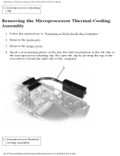
... clip Removing the Microprocessor Thermal-Cooling Assembly 1. Remove the hinge cover. 4. Remove the keyboard. 3. Pry open the clip by pivoting the top of the screwdriver toward the right side of the computer. 1 microprocessor thermalcooling assembly file:///F|/Service%20Manuals/Dell/Latitude/c840/thermal.htm (2 of the microprocessor retaining clip. Insert a non-marring plastic scribe into...
... clip Removing the Microprocessor Thermal-Cooling Assembly 1. Remove the hinge cover. 4. Remove the keyboard. 3. Pry open the clip by pivoting the top of the screwdriver toward the right side of the computer. 1 microprocessor thermalcooling assembly file:///F|/Service%20Manuals/Dell/Latitude/c840/thermal.htm (2 of the microprocessor retaining clip. Insert a non-marring plastic scribe into...
Service Manual
Page 41
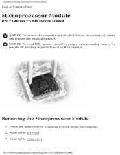
.... Microprocessor Module: Dell Latitude C840 Service Manual Back to Work Inside the Computer." 2. Remove the keyboard. 3. Removing the Microprocessor Module 1. NOTICE: To avoid ESD, ground yourself by using a wrist grounding strap or by periodically touching unpainted metal on the computer. Follow the instructions in "Preparing to Contents Page Microprocessor Module Dell™ Latitude™ C840 Service Manual...
.... Microprocessor Module: Dell Latitude C840 Service Manual Back to Work Inside the Computer." 2. Remove the keyboard. 3. Removing the Microprocessor Module 1. NOTICE: To avoid ESD, ground yourself by using a wrist grounding strap or by periodically touching unpainted metal on the computer. Follow the instructions in "Preparing to Contents Page Microprocessor Module Dell™ Latitude™ C840 Service Manual...
Service Manual
Page 46
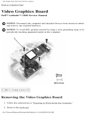
....5 x 8-mm screws (3) Removing the Video Graphics Board 1. Remove the keyboard. Follow the instructions in "Preparing to Contents Page Video Graphics Board Dell™ Latitude™ C840 Service Manual NOTICE: Disconnect the computer and attached devices from electrical outlets and remove any installed batteries. file:///F|/Service%20Manuals/Dell/Latitude/c840/vidbd.htm (1 of 2) [2/28/2004 8:03:42 AM]
....5 x 8-mm screws (3) Removing the Video Graphics Board 1. Remove the keyboard. Follow the instructions in "Preparing to Contents Page Video Graphics Board Dell™ Latitude™ C840 Service Manual NOTICE: Disconnect the computer and attached devices from electrical outlets and remove any installed batteries. file:///F|/Service%20Manuals/Dell/Latitude/c840/vidbd.htm (1 of 2) [2/28/2004 8:03:42 AM]
Service Manual
Page 49
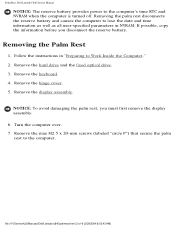
file:///F|/Service%20Manuals/Dell/Latitude/c840/palmrest.htm (2 of 4) [2/28/2004 8:03:43 AM] Remove the hard drive and the fixed optical drive. 3. Remove the display assembly. Turn the computer over. 7. ... parameters in NVRAM. Remove the keyboard. 4. If possible, copy the information before you must first remove the display assembly. 6. Removing the palm rest disconnects the reserve battery and causes the computer to Work Inside the Computer." 2. Remove the hinge cover. 5. Removing the Palm Rest 1. Palm Rest: Dell Latitude C840 Service Manual NOTICE: The reserve...
file:///F|/Service%20Manuals/Dell/Latitude/c840/palmrest.htm (2 of 4) [2/28/2004 8:03:43 AM] Remove the hard drive and the fixed optical drive. 3. Remove the display assembly. Turn the computer over. 7. ... parameters in NVRAM. Remove the keyboard. 4. If possible, copy the information before you must first remove the display assembly. 6. Removing the palm rest disconnects the reserve battery and causes the computer to Work Inside the Computer." 2. Remove the hinge cover. 5. Removing the Palm Rest 1. Palm Rest: Dell Latitude C840 Service Manual NOTICE: The reserve...
Service Manual
Page 53
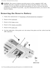
...is turned off. Remove the keyboard. 3. Remove the palm rest. 6. Remove the hinge cover. 4. On the underside of 3) [2/28/2004 8:03:44 AM] Follow the instructions in NVRAM. Remove the display assembly. 5. Reserve Battery: Dell Latitude C840 Service Manual NOTICE: The reserve... battery provides power to Work Inside the Computer." 2. If possible, copy the information before you remove the reserve battery. file:///F|/Service%20Manuals/Dell/Latitude/c840/resbatt.htm (2 of the palm rest,...
...is turned off. Remove the keyboard. 3. Remove the palm rest. 6. Remove the hinge cover. 4. On the underside of 3) [2/28/2004 8:03:44 AM] Follow the instructions in NVRAM. Remove the display assembly. 5. Reserve Battery: Dell Latitude C840 Service Manual NOTICE: The reserve... battery provides power to Work Inside the Computer." 2. If possible, copy the information before you remove the reserve battery. file:///F|/Service%20Manuals/Dell/Latitude/c840/resbatt.htm (2 of the palm rest,...
Service Manual
Page 56
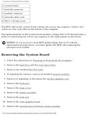
...28/2004 8:03:45 AM] Follow the instructions in "Preparing to the replacement system board. Remove the hinge cover. 8. file:///F|/Service%20Manuals/Dell/Latitude/c840/sysboard.htm (2 of the computer. Remove (if migrating) or disconnect the modem daughter card. 6. The replacement kit for the system board ... Remove the hard drive and the fixed optical drive. 3. Remove any installed Mini PCI Cards. 4. Removing the System Board 1. Remove the keyboard. 7. Remove the display assembly. 9. NOTICE: If you received a flash BIOS update floppy disk or CD with the replacement microprocessor, you ...
...28/2004 8:03:45 AM] Follow the instructions in "Preparing to the replacement system board. Remove the hinge cover. 8. file:///F|/Service%20Manuals/Dell/Latitude/c840/sysboard.htm (2 of the computer. Remove (if migrating) or disconnect the modem daughter card. 6. The replacement kit for the system board ... Remove the hard drive and the fixed optical drive. 3. Remove any installed Mini PCI Cards. 4. Removing the System Board 1. Remove the keyboard. 7. Remove the display assembly. 9. NOTICE: If you received a flash BIOS update floppy disk or CD with the replacement microprocessor, you ...

Service Manual
Page 61
Battery and Module Bay Latches: Dell Latitude C840 Service Manual 1 wear ribs (2 on the inside of 3) [2/28/2004 8:03:46 AM] Remove the ... 5 bottom case 6 latch housing (2) 7 latch buttons (2) 8 location of the bottom case without loosening the upper latch assembly. file:///F|/Service%20Manuals/Dell/Latitude/c840/baylatch.htm (2 of the bottom case. Remove the display assembly. 5. Follow the instructions in place. If the upper latch assembly does come loose:... the underside of snap tabs (2) Removing and Replacing the Battery and Module Bay Latches 1. Remove the keyboard. 3.
Battery and Module Bay Latches: Dell Latitude C840 Service Manual 1 wear ribs (2 on the inside of 3) [2/28/2004 8:03:46 AM] Remove the ... 5 bottom case 6 latch housing (2) 7 latch buttons (2) 8 location of the bottom case without loosening the upper latch assembly. file:///F|/Service%20Manuals/Dell/Latitude/c840/baylatch.htm (2 of the bottom case. Remove the display assembly. 5. Follow the instructions in place. If the upper latch assembly does come loose:... the underside of snap tabs (2) Removing and Replacing the Battery and Module Bay Latches 1. Remove the keyboard. 3.

Service Manual
Page 63
... metal on the computer. Remove the keyboard. 3. Follow the instructions in "Preparing to Contents Page Battery Charger Board Dell™ Latitude™ C840 Service Manual NOTICE: Disconnect the computer and attached devices from electrical outlets and remove any installed batteries. Remove the hinge cover. Battery Charger Board: Dell Latitude C840 Service Manual Back to Work Inside the...
... metal on the computer. Remove the keyboard. 3. Follow the instructions in "Preparing to Contents Page Battery Charger Board Dell™ Latitude™ C840 Service Manual NOTICE: Disconnect the computer and attached devices from electrical outlets and remove any installed batteries. Remove the hinge cover. Battery Charger Board: Dell Latitude C840 Service Manual Back to Work Inside the...
User Guide
Page 2
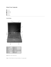
About Your Computer Front View Left Side View Right Side View Back View Bottom View Front View 1 display latch 8 touch pad 2 display 9 battery bay 3 device status lights 10 module bay 4 air vent 11 touch pad/track stick buttons 5 keyboard status lights 12 Dell™ AccessDirect™ button 6 keyboard 13 power button 7 track stick 14 microphone Display Latch - Keeps the display closed. Display - For more information on using your color display, see "Using the Display."
About Your Computer Front View Left Side View Right Side View Back View Bottom View Front View 1 display latch 8 touch pad 2 display 9 battery bay 3 device status lights 10 module bay 4 air vent 11 touch pad/track stick buttons 5 keyboard status lights 12 Dell™ AccessDirect™ button 6 keyboard 13 power button 7 track stick 14 microphone Display Latch - Keeps the display closed. Display - For more information on using your color display, see "Using the Display."
User Guide
Page 3
... of data, never turn on the fans when the computer gets hot. Doing so can cause fire or electric shock by shorting out interior components. Keyboard Status Lights Device Status Lights Device Status Lights Turns on when you turn off ). ¡ Flashing orange: The battery charge is low. ¡ Solid orange...
... of data, never turn on the fans when the computer gets hot. Doing so can cause fire or electric shock by shorting out interior components. Keyboard Status Lights Device Status Lights Device Status Lights Turns on when you turn off ). ¡ Flashing orange: The battery charge is low. ¡ Solid orange...


