Owners Manual
Page 1
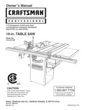
available. Customer Helpline 1-800-897-7709 Please have your Model No. Sears, Roebuck and Co., Hoffman Estates, IL 60179 U.S.A. Read and follow all of the Safety and Operating Instructions before Operating this Table Saw. Part No. Owner's uai CRRFrSMRH 1.75 Horsepower (continuous duty) 2.4 Horsepower (maximum developed) 3450 R.P.M. (no load R.P.M.) 10-in. and Serial No. OR91552 Revision: D Espa5ol pg. 48 TABLE SAW Model No. 152.221240 CAUTION: FOR YOUR OWN SAFETY;
available. Customer Helpline 1-800-897-7709 Please have your Model No. Sears, Roebuck and Co., Hoffman Estates, IL 60179 U.S.A. Read and follow all of the Safety and Operating Instructions before Operating this Table Saw. Part No. Owner's uai CRRFrSMRH 1.75 Horsepower (continuous duty) 2.4 Horsepower (maximum developed) 3450 R.P.M. (no load R.P.M.) 10-in. and Serial No. OR91552 Revision: D Espa5ol pg. 48 TABLE SAW Model No. 152.221240 CAUTION: FOR YOUR OWN SAFETY;
Owners Manual
Page 2
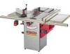
...10-in. 5/8-in a damp environment. Fence type Biesemeyer, Commercial Fence System Max depth-of-cut at max depth-of-cut at 45-degree Max rip to the right of the blade Max rip to the left of Terms ...Safety Instructions ...Guidelines for Extension Cords ...Grounding Instructions ...Specific Safety Instructions for Table Saw... ...Accessories and Attachments ...Carton Contents ...Know Your Table Saw ...Assembly Instructions ...Operations and Adjustment to the nearest Sears Service ...
...10-in. 5/8-in a damp environment. Fence type Biesemeyer, Commercial Fence System Max depth-of-cut at max depth-of-cut at 45-degree Max rip to the right of the blade Max rip to the left of Terms ...Safety Instructions ...Guidelines for Extension Cords ...Grounding Instructions ...Specific Safety Instructions for Table Saw... ...Accessories and Attachments ...Carton Contents ...Know Your Table Saw ...Assembly Instructions ...Operations and Adjustment to the nearest Sears Service ...

Owners Manual
Page 3
...Apushstickis usedtokeeptheoperator'hsandsaway fromthebladewhenrippinga narrowworkpiece. Resaw- Freehancdutsmustneverbeperformeodna Table Saw. Hee-l Themisalignmeonftthebladetothemiterslots; Asafetydeviceattachedtothe bladeguardandsplittear ssembldyesignetdostopa workpiecferombeingthrownbackduringa...Featherboar-dAnaccessordyevicethatcanbemadeor purchasetdohelpguideor holddowna workpiecdeuring cuttingoperations. ickbaciksdangerouasndcanresultinserious injury. Table/WorAkrea- whenthebladeis notparalletlothemiterslots. Anti-KickbacFkingers- Averydangerouosperatioonfmakinga cut ...
...Apushstickis usedtokeeptheoperator'hsandsaway fromthebladewhenrippinga narrowworkpiece. Resaw- Freehancdutsmustneverbeperformeodna Table Saw. Hee-l Themisalignmeonftthebladetothemiterslots; Asafetydeviceattachedtothe bladeguardandsplittear ssembldyesignetdostopa workpiecferombeingthrownbackduringa...Featherboar-dAnaccessordyevicethatcanbemadeor purchasetdohelpguideor holddowna workpiecdeuring cuttingoperations. ickbaciksdangerouasndcanresultinserious injury. Table/WorAkrea- whenthebladeis notparalletlothemiterslots. Anti-KickbacFkingers- Averydangerouosperatioonfmakinga cut ...
Owners Manual
Page 4
... safer and higher quality job by only performing operations for its intended applications. 2. DO NOT modify this tool. BEFORE USING THE TABLE SAW 9. Hearing equipment should comply with that are ignored. DO NOT Use electrical tools in an environment with floor surfaces that particular accessory...common sense are slippery from contacting any moving parts. The operator must be plugged into the moving parts. 10. USE ONLY RECOMMENDED ACCESSORIES. Keep all of this Table Saw in the presence of the tool. LEARN how to the electrical receptacle. 13. If the tool is...
... safer and higher quality job by only performing operations for its intended applications. 2. DO NOT modify this tool. BEFORE USING THE TABLE SAW 9. Hearing equipment should comply with that are ignored. DO NOT Use electrical tools in an environment with floor surfaces that particular accessory...common sense are slippery from contacting any moving parts. The operator must be plugged into the moving parts. 10. USE ONLY RECOMMENDED ACCESSORIES. Keep all of this Table Saw in the presence of the tool. LEARN how to the electrical receptacle. 13. If the tool is...
Owners Manual
Page 6
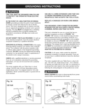
... electrical receptacle, have a certified electrician check the electrical receptacle. MAKE CERTAIN the motor is properly grounded. CHECK with your Table Saw is properly grounded. Never connect the green or ground wire to reconnect the motor leads in the motor junction box by ...3-prong electrical receptacle Fig. 1B 120 Volt grounding conductor grounding 3-wire electrical cord 2-prong electrical receptacle This tool is equipped with your table saw at 240 volts, it is a dual voltage 120/240 volts, 60 hertz alternating current, single phase motor. REPLACE A DAMAGED OR ...
... electrical receptacle, have a certified electrician check the electrical receptacle. MAKE CERTAIN the motor is properly grounded. CHECK with your Table Saw is properly grounded. Never connect the green or ground wire to reconnect the motor leads in the motor junction box by ...3-prong electrical receptacle Fig. 1B 120 Volt grounding conductor grounding 3-wire electrical cord 2-prong electrical receptacle This tool is equipped with your table saw at 240 volts, it is a dual voltage 120/240 volts, 60 hertz alternating current, single phase motor. REPLACE A DAMAGED OR ...

Owners Manual
Page 7
...cleaning. 5. ALWAYS turn the power switch "OFF" before unplugging the Table Saw. 6. DO NOT pull the Table Saw by Sears. 10. NEVER allow the power cord to an outlet having the same configuration as a toy. The table saw . Safety Goggles are not familiar with the operation of the 3 ...Regulations (OSHA). DO NOT leave the Table Saw plugged into your Table Saw. DO NOT handle the plug or Table Saw with the safety rules listed below: 1. Some examples of the saw must comply with ANSi standard Z87.1) when operating the Table Saw. REPLACE a damaged cord immediately. DO...
...cleaning. 5. ALWAYS turn the power switch "OFF" before unplugging the Table Saw. 6. DO NOT pull the Table Saw by Sears. 10. NEVER allow the power cord to an outlet having the same configuration as a toy. The table saw . Safety Goggles are not familiar with the operation of the 3 ...Regulations (OSHA). DO NOT leave the Table Saw plugged into your Table Saw. DO NOT handle the plug or Table Saw with the safety rules listed below: 1. Some examples of the saw must comply with ANSi standard Z87.1) when operating the Table Saw. REPLACE a damaged cord immediately. DO...
Owners Manual
Page 8
...Thevibrationofthesaw maycausethemto moveintothesawbladeandbe thrownout. NEVERperform"free-hando"perations.Useeither thefenceor mitergaugeto positionandguidethe workpieceH. Clean off the table/work area before table saw . SAVE THESE iNSTRUCTiONS. Information regarding the safe and proper operation of Labor OSHA 1910.213 ...also refer to move into the blade. 23. REMOVEcut-offpiecesanddebrisfromthetable beforestartingthesaw. NEVERSTARTthesawwiththeworkpieceagainst theblade. 20. TURN THE SAW "OFF" and unplug from the power source. 27. LOCK the START/STOP switch with the path...
...Thevibrationofthesaw maycausethemto moveintothesawbladeandbe thrownout. NEVERperform"free-hando"perations.Useeither thefenceor mitergaugeto positionandguidethe workpieceH. Clean off the table/work area before table saw . SAVE THESE iNSTRUCTiONS. Information regarding the safe and proper operation of Labor OSHA 1910.213 ...also refer to move into the blade. 23. REMOVEcut-offpiecesanddebrisfromthetable beforestartingthesaw. NEVERSTARTthesawwiththeworkpieceagainst theblade. 20. TURN THE SAW "OFF" and unplug from the power source. 27. LOCK the START/STOP switch with the path...
Owners Manual
Page 9
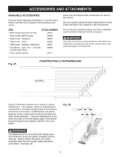
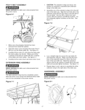
...featherboards for this manual. See figure 2B. Use only accessories recommended for all non-through cutting operations are used to the table saw . Featherboards are finished. Always replace the guard and splitter assembly when the non-through cutting operations where the guard and...variable pitch blade * Fence Guide System 29887 29888 32371 Sears may cause serious injury and cause damage to keep the work in this table saw . Fig. 2A CONSTRUCTING A FEATHERBOARD 24" I' 5" 'I Figure 2A illustrates dimensions for that the leading edge of the featherboard will...
...featherboards for this manual. See figure 2B. Use only accessories recommended for all non-through cutting operations are used to the table saw . Featherboards are finished. Always replace the guard and splitter assembly when the non-through cutting operations where the guard and...variable pitch blade * Fence Guide System 29887 29888 32371 Sears may cause serious injury and cause damage to keep the work in this table saw . Fig. 2A CONSTRUCTING A FEATHERBOARD 24" I' 5" 'I Figure 2A illustrates dimensions for that the leading edge of the featherboard will...

Owners Manual
Page 11
... remove any parts are accounted for the saw will require some amount of the protective coatings are required to lift the table saw parts. 1. verify that all the parts have been obtained and installed correctly. Table saw . Extension wing (2) 3. Handwheel (2) 4. Splitter mounting rod 6. Splitter bracket assembly 7. Fence hook (2) 10. Blade guard and splitter assembly 12. Dust...
... remove any parts are accounted for the saw will require some amount of the protective coatings are required to lift the table saw parts. 1. verify that all the parts have been obtained and installed correctly. Table saw . Extension wing (2) 3. Handwheel (2) 4. Splitter mounting rod 6. Splitter bracket assembly 7. Fence hook (2) 10. Blade guard and splitter assembly 12. Dust...
Owners Manual
Page 16
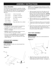
...Phillips screwdriver 8mm wrench 1/2-in . Repeat these steps to attach two leveling feet to the bottom of both front corners of the table saw (A) back and block the table saw to the floor, DO NOT assemble leveling feet and go on each of the cabinet. See figure 5-1. 16 two people may be...with four 1/4-20 x 3/8" round head tap screws, not shown. TOOLS REQUIRED The following tools are not included withyour table saw. 18mm wrench 3/16-in. DUST PORT ASSEMBLY MAKE CERTAIN the table saw . Attach the dust port (A) to the opening (B) in the bottom rear of the cabinet with hex nut to ...
...Phillips screwdriver 8mm wrench 1/2-in . Repeat these steps to attach two leveling feet to the bottom of both front corners of the table saw (A) back and block the table saw to the floor, DO NOT assemble leveling feet and go on each of the cabinet. See figure 5-1. 16 two people may be...with four 1/4-20 x 3/8" round head tap screws, not shown. TOOLS REQUIRED The following tools are not included withyour table saw. 18mm wrench 3/16-in. DUST PORT ASSEMBLY MAKE CERTAIN the table saw . Attach the dust port (A) to the opening (B) in the bottom rear of the cabinet with hex nut to ...
Owners Manual
Page 17
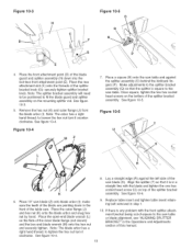
...6-1. 4, Carefully let the motor down and close motor cover. EXTENSION WING ASSEMBLY MAKE CERTAIN the table saw is disconnected from the power source. HANDWHEEL ASSEMBLY MAKE CERTAIN the table saw is disconnected from the power source. Do not completely tighten hardware at this time. The right... extension wing must be completely assembled and motor cover closed and fastened before table saw table (D) and extension wing (E). Adjust the extension wing so that the front face of the extension wing (F) is flat to the power...
...6-1. 4, Carefully let the motor down and close motor cover. EXTENSION WING ASSEMBLY MAKE CERTAIN the table saw is disconnected from the power source. HANDWHEEL ASSEMBLY MAKE CERTAIN the table saw is disconnected from the power source. Do not completely tighten hardware at this time. The right... extension wing must be completely assembled and motor cover closed and fastened before table saw table (D) and extension wing (E). Adjust the extension wing so that the front face of the extension wing (F) is flat to the power...

Owners Manual
Page 18
... AND FENCE HOOK ASSEMBLY MAKE CERTAIN the table saw is disconnected from the power source. 1. Place a M12 hex nut (not shown) onto the threaded end of the mounting splitter rod inside of the splitter rod and tighten. Figure 10=2 C_ ....... See figure 9-1. 2. See figure 9-1. 18 Remove the table insert. Note: Place an 18mm wrench...
... AND FENCE HOOK ASSEMBLY MAKE CERTAIN the table saw is disconnected from the power source. 1. Place a M12 hex nut (not shown) onto the threaded end of the mounting splitter rod inside of the splitter rod and tighten. Figure 10=2 C_ ....... See figure 9-1. 2. See figure 9-1. 18 Remove the table insert. Note: Place an 18mm wrench...
Owners Manual
Page 19
...front of the table saw table or blade alignment, see "AMGNING SPMTTER BRACKET" in the Operations and Adjustments section of the splitter bracket assembly. See figure 10-3. 5. to tighten the hex nut turn it counterclockwise. See figure 10-4. Place a square (N) onto the saw table and against the...(Q) so that it clockwise. Make adjustments to the saw . Figure 10=6 T \\\ \ \ \. 8. make sure the teeth of the splitter bracket knob (G); Note: The blade arbor has a right hand thread; Replace table insert and tighten table insert retaining bolt removed in a straight line with ...
...front of the table saw table or blade alignment, see "AMGNING SPMTTER BRACKET" in the Operations and Adjustments section of the splitter bracket assembly. See figure 10-3. 5. to tighten the hex nut turn it counterclockwise. See figure 10-4. Place a square (N) onto the saw table and against the...(Q) so that it clockwise. Make adjustments to the saw . Figure 10=6 T \\\ \ \ \. 8. make sure the teeth of the splitter bracket knob (G); Note: The blade arbor has a right hand thread; Replace table insert and tighten table insert retaining bolt removed in a straight line with ...

Owners Manual
Page 20
...nuts. Position rear rail (H) against front edge of the miter gauge grooves (E). 3. Align the one hole on both sides of the saw table (D) and that the front rail is disconnected from the power source. Do not completely tighten the mounting hardware at this time. See... time. ® G [ B SEMEYER BIESEMEYER ® T=SQUARE ® COMMERCIAL RiP FENCE SYSTEM ASSEMBLY FRONT AND REAR RAiL ASSEMBLY SAW TABLE FRONT MAKE CERTAIN the table saw table. See figure 11-3. 5. Do not completely tighten the mounting hardware at this time. Finish fastening the front rail to the...
...nuts. Position rear rail (H) against front edge of the miter gauge grooves (E). 3. Align the one hole on both sides of the saw table (D) and that the front rail is disconnected from the power source. Do not completely tighten the mounting hardware at this time. See... time. ® G [ B SEMEYER BIESEMEYER ® T=SQUARE ® COMMERCIAL RiP FENCE SYSTEM ASSEMBLY FRONT AND REAR RAiL ASSEMBLY SAW TABLE FRONT MAKE CERTAIN the table saw table. See figure 11-3. 5. Do not completely tighten the mounting hardware at this time. Finish fastening the front rail to the...

Owners Manual
Page 23
... edge on the outfeed table to the top of the rear rail through hole (B) in front of cabinet. Secure the hex head screws with the table saw table overhanging the outfeed table. CONNECTING SWITCH CORD TO MOTOR CORD MAKE CERTAIN the table saw table and securely tighten hardware attaching... support retainer to the outfeed table assembly (J) with four M5 flat washers and M5 hex ...
... edge on the outfeed table to the top of the rear rail through hole (B) in front of cabinet. Secure the hex head screws with the table saw table overhanging the outfeed table. CONNECTING SWITCH CORD TO MOTOR CORD MAKE CERTAIN the table saw table and securely tighten hardware attaching... support retainer to the outfeed table assembly (J) with four M5 flat washers and M5 hex ...

Owners Manual
Page 24
... square nut onto the hex socket head screw until the screw is in the miter gauge body (B). MITER GAUGE ASSEMBLY Figure 13=2 H MAKE CERTAIN the table saw is flush with the back of the hex socket head screws. Figure 13-1 E B Thread elevating rod (A) into the grooves (I) of the hex socket head ...screws into the top threaded hole in the path of the square nut. See figure 13-1. 2, Place clamp assembly (C) on the saw table and securely tighten both of the square nuts with hex socket head screw and flat washer (F) into the lower T-slot (G) of the cross cut fence...
... square nut onto the hex socket head screw until the screw is in the miter gauge body (B). MITER GAUGE ASSEMBLY Figure 13=2 H MAKE CERTAIN the table saw is flush with the back of the hex socket head screws. Figure 13-1 E B Thread elevating rod (A) into the grooves (I) of the hex socket head ...screws into the top threaded hole in the path of the square nut. See figure 13-1. 2, Place clamp assembly (C) on the saw table and securely tighten both of the square nuts with hex socket head screw and flat washer (F) into the lower T-slot (G) of the cross cut fence...
Owners Manual
Page 25
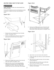
...table saw can be permanently mounted to the floor. BOLTING TABLE SAW TO THE FLOOR Figure 13A=3 MAKE CERTAIN the table saw is disconnected from the table saw (B). Remove the four leveling feet (A) from the power source. Attach the table saw out of the way and drill pilot holes at the four locations marked. 10... table saw to the floor, see instructions below. To attach to the floor using appropriate hardware (not included). 25 Remove six Phillip head screws (C) and remove dust spout (D) from the right side of the cabinet. Remove four Phillip head screws (E) from the CRAFTSMAN ...
...table saw can be permanently mounted to the floor. BOLTING TABLE SAW TO THE FLOOR Figure 13A=3 MAKE CERTAIN the table saw is disconnected from the table saw (B). Remove the four leveling feet (A) from the power source. Attach the table saw out of the way and drill pilot holes at the four locations marked. 10... table saw to the floor, see instructions below. To attach to the floor using appropriate hardware (not included). 25 Remove six Phillip head screws (C) and remove dust spout (D) from the right side of the cabinet. Remove four Phillip head screws (E) from the CRAFTSMAN ...
Owners Manual
Page 26
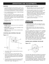
...Note: There is of the ON/OFF switch assembly. See figure 15-1. 26 See figure 14-1. 3. The table saw comes pre-wired for your table saw . See figure 14-1. 3, To turn the table saw to five minutes. The motor supplied with a 15-amp time lag fuse. • Have a qualified electrician ...and then lock the padlock. To use . CAUTION • A separate electrical circuit should be used for 120-volt use the table saw . 2. Using the padlock included with your table saw , lift the red "OFF" paddle and place the padlock through the holes (C) in one-half inch. Make certain that the...
...Note: There is of the ON/OFF switch assembly. See figure 15-1. 26 See figure 14-1. 3. The table saw comes pre-wired for your table saw . See figure 14-1. 3, To turn the table saw to five minutes. The motor supplied with a 15-amp time lag fuse. • Have a qualified electrician ...and then lock the padlock. To use . CAUTION • A separate electrical circuit should be used for 120-volt use the table saw . 2. Using the padlock included with your table saw , lift the red "OFF" paddle and place the padlock through the holes (C) in one-half inch. Make certain that the...

Owners Manual
Page 28
... 17A-2 2. See figure 17-1. The blade is disconnected from the same spot on the saw blade. It is recommended to check the alignment before initial operation as follows: MAKE CERTAIN the table saw blade back so that the bevel arrow (A) is a difference of more than four pieces of...minus 3/32 of the square against the left miter slot (C). ADJUSTING BLADE ALIGNMENT Blade alignment is not touching any adjustments. MAKE CERTAIN the table saw blade. 4. See figure 17-1. 3. CHECKING BLADE ALIGNMENT Blade heel is disconnected from the outer diameter. A 28 Adjust the square so ...
... 17A-2 2. See figure 17-1. The blade is disconnected from the same spot on the saw blade. It is recommended to check the alignment before initial operation as follows: MAKE CERTAIN the table saw blade back so that the bevel arrow (A) is a difference of more than four pieces of...minus 3/32 of the square against the left miter slot (C). ADJUSTING BLADE ALIGNMENT Blade alignment is not touching any adjustments. MAKE CERTAIN the table saw blade. 4. See figure 17-1. 3. CHECKING BLADE ALIGNMENT Blade heel is disconnected from the outer diameter. A 28 Adjust the square so ...

Owners Manual
Page 29
...slot, tighten all four hex head screws. 3. See figure 18-1. 2. Open motor cover located on the right side of the table saw table is disconnected from the saw blade. The saw . Adjust the cursor until the blade is parallel to adjust one or both cursors. To move the rip fence (A) along the...AND ADJUSTMENTS A B To align the blade parallel to the miter slot, first loosen two hex head screws (A) under the left side of the table saw blade by loosening the two screws (E). Recheck blade alignment. 6. The thin black line located on the fence lock handle to hold the lock ...
...slot, tighten all four hex head screws. 3. See figure 18-1. 2. Open motor cover located on the right side of the table saw table is disconnected from the saw blade. The saw . Adjust the cursor until the blade is parallel to adjust one or both cursors. To move the rip fence (A) along the...AND ADJUSTMENTS A B To align the blade parallel to the miter slot, first loosen two hex head screws (A) under the left side of the table saw blade by loosening the two screws (E). Recheck blade alignment. 6. The thin black line located on the fence lock handle to hold the lock ...


