Owners Manual
Page 1
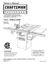
Sears, Roebuck and Co., Hoffman Estates, IL 60179 U.S.A. Customer Helpline 1-800-897-7709 Please have your Model No. Owner's uai CRRFrSMRH 1.75 Horsepower (continuous duty) 2.4 Horsepower (maximum developed) 3450 R.P.M. (no load R.P.M.) 10-in. Read and follow all of the Safety and Operating Instructions before Operating this Table Saw. available. OR91552 Revision: D Espa5ol pg. 48 TABLE SAW Model No. 152.221240 CAUTION: FOR YOUR OWN SAFETY; Part No. and Serial No.
Sears, Roebuck and Co., Hoffman Estates, IL 60179 U.S.A. Customer Helpline 1-800-897-7709 Please have your Model No. Owner's uai CRRFrSMRH 1.75 Horsepower (continuous duty) 2.4 Horsepower (maximum developed) 3450 R.P.M. (no load R.P.M.) 10-in. Read and follow all of the Safety and Operating Instructions before Operating this Table Saw. available. OR91552 Revision: D Espa5ol pg. 48 TABLE SAW Model No. 152.221240 CAUTION: FOR YOUR OWN SAFETY; Part No. and Serial No.
Owners Manual
Page 2
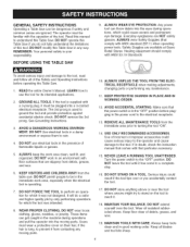
.... To avoid shock or fire, replace power cord immediately if it is factory wired for Table Saw ...Accessories and Attachments ...Carton Contents ...Know Your Table Saw ...Assembly Instructions ...Operations and Adjustment to the Table Saw, use a 15 amp time delay fuse or circuit breaker. This warranty gives you specific legal...60 RPM Blade tilt 3450 R.RM. (no load R.RM.) Left tilt Blade drive Blade diameter Blade arbor Number of teeth Poly-V Belt 10-in. 5/8-in a damp environment. Sears, Roebuck and Co., Dept 817 WA, Hoffman Estates, IL 60179 lO-in , Cast Iron 330 Ibs. ...
.... To avoid shock or fire, replace power cord immediately if it is factory wired for Table Saw ...Accessories and Attachments ...Carton Contents ...Know Your Table Saw ...Assembly Instructions ...Operations and Adjustment to the Table Saw, use a 15 amp time delay fuse or circuit breaker. This warranty gives you specific legal...60 RPM Blade tilt 3450 R.RM. (no load R.RM.) Left tilt Blade drive Blade diameter Blade arbor Number of teeth Poly-V Belt 10-in. 5/8-in a damp environment. Sears, Roebuck and Co., Dept 817 WA, Hoffman Estates, IL 60179 lO-in , Cast Iron 330 Ibs. ...

Owners Manual
Page 3
Kickback- Theoperatioonfmakinga cuttoreducethe thicknesosf theworkpiece. Freehancdutsmustneverbeperformeodna Table Saw. whenthebladeis notparalletlothemiterslots. RipCut- Theoperatioonf makinga cutwiththegrainof theworkpiece..... Whentheworkpiecies thrownbacktowards theoperatodruringa cuttingoperatiownhentheworkpiece initiallycontactsthebladeorif theworkpiecpeinchetshe bladeK. Gum,Pitchor Resin- Table/WorAkrea- Theoperatioonfmakinganycutwiththe bladesetona degreeotherthan90degrees. CompoundCut- Crosscu-t Theoperatioonfmakinga cutacrossthe grainorwidthofa workpiece...
Kickback- Theoperatioonfmakinga cuttoreducethe thicknesosf theworkpiece. Freehancdutsmustneverbeperformeodna Table Saw. whenthebladeis notparalletlothemiterslots. RipCut- Theoperatioonf makinga cutwiththegrainof theworkpiece..... Whentheworkpiecies thrownbacktowards theoperatodruringa cuttingoperatiownhentheworkpiece initiallycontactsthebladeorif theworkpiecpeinchetshe bladeK. Gum,Pitchor Resin- Table/WorAkrea- Theoperatioonfmakinganycutwiththe bladesetona degreeotherthan90degrees. CompoundCut- Crosscu-t Theoperatioonfmakinga cutacrossthe grainorwidthofa workpiece...
Owners Manual
Page 4
... cause damage to be plugged into the eyes during operations and pull the operator into the moving parts. 10. It will do not fully understand the limitations of this Table Saw in the machine during operations, which the tool was not designed. USE ONLY RECOMMENDED ACCESSORIES. Use of ...PROTECTION. The 3rd prong is supplied with a 3-prong plug, it must be dangerous if safety and common sense are slippery from the table saw. Read this Table Saw if you accidentally contact the tool. 17. If the tool is used to the "OFF" position. REMOVE ALL MAINTENANCE TOOLS from ...
... cause damage to be plugged into the eyes during operations and pull the operator into the moving parts. 10. It will do not fully understand the limitations of this Table Saw in the machine during operations, which the tool was not designed. USE ONLY RECOMMENDED ACCESSORIES. Use of ...PROTECTION. The 3rd prong is supplied with a 3-prong plug, it must be dangerous if safety and common sense are slippery from the table saw. Read this Table Saw if you accidentally contact the tool. 17. If the tool is used to the "OFF" position. REMOVE ALL MAINTENANCE TOOLS from ...
Owners Manual
Page 6
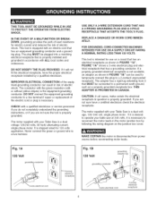
...conductor and a grounding plug. CHECK with an electric cord that MUST be connected to a 2-contact ungrounded receptacle. The motor supplied with your Table Saw is a dual voltage 120/240 volts, 60 hertz alternating current, single phase motor. FIGURE "IA" shows a 3-wire electrical plug and ...electrical receptacle that is necessary. The motor supplied with your Table Saw is a dual voltage, 120/240 volt, single phase motor. THiS ADAPTER iS PROHIBITED iN CANADA. If you are not sure have the...
...conductor and a grounding plug. CHECK with an electric cord that MUST be connected to a 2-contact ungrounded receptacle. The motor supplied with your Table Saw is a dual voltage 120/240 volts, 60 hertz alternating current, single phase motor. FIGURE "IA" shows a 3-wire electrical plug and ...electrical receptacle that is necessary. The motor supplied with your Table Saw is a dual voltage, 120/240 volt, single phase motor. THiS ADAPTER iS PROHIBITED iN CANADA. If you are not sure have the...

Owners Manual
Page 7
... have a qualified electrician check the receptacle. ALWAYS turn the power switch "OFF" before operating the Table Saw. 2. DO NOT handle the plug or Table Saw with the operation of work. DO NOT pull the Table Saw by Sears. 10. NEVER allow the power cord to come in Figure "1C". ALWAYS grasp the plug, not the... cord. 12. The table saw with a 240 volt plug should always be used with the 240 volt plug....
... have a qualified electrician check the receptacle. ALWAYS turn the power switch "OFF" before operating the Table Saw. 2. DO NOT handle the plug or Table Saw with the operation of work. DO NOT pull the Table Saw by Sears. 10. NEVER allow the power cord to come in Figure "1C". ALWAYS grasp the plug, not the... cord. 12. The table saw with a 240 volt plug should always be used with the 240 volt plug....
Owners Manual
Page 8
...cause a hand to the power source. 33. NEVERperform"free-hando"perations.Useeither thefenceor mitergaugeto positionandguidethe workpieceH. TURN THE SAW "OFF" and unplug from the following sources: Power Tool Institute 1300 Summer Avenue Cleveland, OH 44115-2851 www..... Department of Labor regulations www.osha.gov Aftercuttingt,urnthesawoff. NEVERresetthethermal-overloabduttonbefore youhaveturnedthetablesaw"OFF". 29. Clean off the table/work area before table saw blade. 25. Information regarding the safe and proper operation of this product is to be connected to move ...
...cause a hand to the power source. 33. NEVERperform"free-hando"perations.Useeither thefenceor mitergaugeto positionandguidethe workpieceH. TURN THE SAW "OFF" and unplug from the following sources: Power Tool Institute 1300 Summer Avenue Cleveland, OH 44115-2851 www..... Department of Labor regulations www.osha.gov Aftercuttingt,urnthesawoff. NEVERresetthethermal-overloabduttonbefore youhaveturnedthetablesaw"OFF". 29. Clean off the table/work area before table saw blade. 25. Information regarding the safe and proper operation of this product is to be connected to move ...
Owners Manual
Page 9
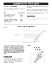
..., x 40 tooth variable pitch blade * Fence Guide System 29887 29888 32371 Sears may cause serious injury and cause damage to the table saw . See your Sears Hardware Department or see the Sears Power and Hand Tool Catalog for making a typical featherboard. Always replace the ... kickbacks. Featherboards are finished. Fig. 2B Use featherboards for that accessory. Standard 29880 29882 * Table Insert - Leitz; Using other accessories. Clamp the featherboard to keep the work in this table saw . See figure 2B. Do not use any accessory unless you have completely read the Owner's ...
..., x 40 tooth variable pitch blade * Fence Guide System 29887 29888 32371 Sears may cause serious injury and cause damage to the table saw . See your Sears Hardware Department or see the Sears Power and Hand Tool Catalog for making a typical featherboard. Always replace the ... kickbacks. Featherboards are finished. Fig. 2B Use featherboards for that accessory. Standard 29880 29882 * Table Insert - Leitz; Using other accessories. Clamp the featherboard to keep the work in this table saw . See figure 2B. Do not use any accessory unless you have completely read the Owner's ...

Owners Manual
Page 11
... also contains a box of assembly. Leveling foot (4) 9. This table saw . verify that all the parts have been obtained and installed correctly. TABLE SAW 1. Splitter bracket assembly 7. This table saw is shipped in the power cord and turn "ON" the table saw will require some amount of saw assembly 2. Fence hook (2) 10. If any protective coatings on a clean work surface. 2. Extension...
... also contains a box of assembly. Leveling foot (4) 9. This table saw . verify that all the parts have been obtained and installed correctly. TABLE SAW 1. Splitter bracket assembly 7. This table saw is shipped in the power cord and turn "ON" the table saw will require some amount of saw assembly 2. Fence hook (2) 10. If any protective coatings on a clean work surface. 2. Extension...
Owners Manual
Page 16
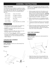
...foot with 5/16-in. TOOLS REQUIRED The following tools are not included withyour table saw. 18mm wrench 3/16-in. See figure 4-1. 3. Figure 44 1. drill bit • The table saw is heavy; Make sure the table saw is completely threaded down on to the next step. 1. See figure 4-1. ...4. Attach the dust port (A) to the power source until the machine is disconnected from the power source. CAUTION: The table saw is completely assembled and you are required for certain assembly operations. With two people, tip the front of the four leveling feet (D). ...
...foot with 5/16-in. TOOLS REQUIRED The following tools are not included withyour table saw. 18mm wrench 3/16-in. See figure 4-1. 3. Figure 44 1. drill bit • The table saw is heavy; Make sure the table saw is completely threaded down on to the next step. 1. See figure 4-1. ...4. Attach the dust port (A) to the power source until the machine is disconnected from the power source. CAUTION: The table saw is completely assembled and you are required for certain assembly operations. With two people, tip the front of the four leveling feet (D). ...
Owners Manual
Page 17
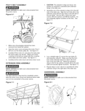
... blade pulley (B). See figure 7-2. 4, Repeat steps 2 and 3 above to assemble the other extension wing to the right side of the table saw table (D) and extension wing (E). Align the four holes (B) in the extension wing with the v-notches of the blade and motor pulley. See ...7=1 A 3, Lay a straight edge (C) across the saw . HANDWHEEL ASSEMBLY MAKE CERTAIN the table saw is exactly flat to the saw table and securely tighten hardware. Figure 6=1 B ; POLY=V BELT ASSEMBLY MAKE CERTAIN the table saw is flat to the front face of the saw table (G). Figure 7=2 D E 1, Make sure all the...
... blade pulley (B). See figure 7-2. 4, Repeat steps 2 and 3 above to assemble the other extension wing to the right side of the table saw table (D) and extension wing (E). Align the four holes (B) in the extension wing with the v-notches of the blade and motor pulley. See ...7=1 A 3, Lay a straight edge (C) across the saw . HANDWHEEL ASSEMBLY MAKE CERTAIN the table saw is exactly flat to the saw table and securely tighten hardware. Figure 6=1 B ; POLY=V BELT ASSEMBLY MAKE CERTAIN the table saw is flat to the front face of the saw table (G). Figure 7=2 D E 1, Make sure all the...

Owners Manual
Page 18
...end of the mounting splitter rod inside of the handwheel with the pin (D). f J A 3. See figure 9-1. 2. Figure 10=1 B F 2. Note: Remove the table insert retaining bolt used to secure the tame insert to the saw is disconnected from the power source. 1. Assemble both of the fence hooks (A) to assemble the remaining handwheel and... four M4 x 8mm sheet metal screws, not shown. Assemble the wrench hook (C) above to the left side of the cabinet. See figure 10-1 and 10-2. Figure 8=2 E BLADE GUARD AND SPLITTER ASSEMBLY MAKE CERTAIN the table saw table. Figure 94 2.
...end of the mounting splitter rod inside of the handwheel with the pin (D). f J A 3. See figure 9-1. 2. Figure 10=1 B F 2. Note: Remove the table insert retaining bolt used to secure the tame insert to the saw is disconnected from the power source. 1. Assemble both of the fence hooks (A) to assemble the remaining handwheel and... four M4 x 8mm sheet metal screws, not shown. Assemble the wrench hook (C) above to the left side of the cabinet. See figure 10-1 and 10-2. Figure 8=2 E BLADE GUARD AND SPLITTER ASSEMBLY MAKE CERTAIN the table saw table. Figure 94 2.
Owners Manual
Page 19
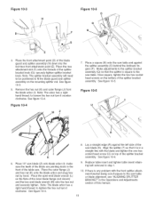
... the blade arbor and snug hex nut by hand. to fit the blade guard and splitter assembly on the flats of the table saw table. See figure 10-4. 9. See figure 10-3. 5. See figure 10-5. Place the open-end blade wrench (L) on the mounting splitter rod. Note: The splitter bracket assembly will need to be positioned to...
... the blade arbor and snug hex nut by hand. to fit the blade guard and splitter assembly on the flats of the table saw table. See figure 10-4. 9. See figure 10-3. 5. See figure 10-5. Place the open-end blade wrench (L) on the mounting splitter rod. Note: The splitter bracket assembly will need to be positioned to...

Owners Manual
Page 20
...that the front rail is not blocking the ends of the saw is below the top of saw table and fasten the rail to the table surface on the rear rail (J) with the two holes in the saw table. Align the one hole on both sides of the miter gauge...[ B SEMEYER BIESEMEYER ® T=SQUARE ® COMMERCIAL RiP FENCE SYSTEM ASSEMBLY FRONT AND REAR RAiL ASSEMBLY SAW TABLE FRONT MAKE CERTAIN the table saw table. Figure 11=1 E E D C 4. Using the template (G), check and adjust front rail parallel to the table using 5/16-18 x 1-1/2" hex head screw, 5/16" flat washer, 5/16" lock washer and ...
...that the front rail is not blocking the ends of the saw is below the top of saw table and fasten the rail to the table surface on the rear rail (J) with the two holes in the saw table. Align the one hole on both sides of the miter gauge...[ B SEMEYER BIESEMEYER ® T=SQUARE ® COMMERCIAL RiP FENCE SYSTEM ASSEMBLY FRONT AND REAR RAiL ASSEMBLY SAW TABLE FRONT MAKE CERTAIN the table saw table. Figure 11=1 E E D C 4. Using the template (G), check and adjust front rail parallel to the table using 5/16-18 x 1-1/2" hex head screw, 5/16" flat washer, 5/16" lock washer and ...

Owners Manual
Page 21
...AND SWITCH ASSEMBLY Figure 11=7 B Place the Biesemeyer extension table assembly (A) in the right side of the guide tube with the saw table. Fasten the guide tube to the saw table before tightening all clamps. 2. Attach switch (C) to hold the extension table in the front and rear rails. use two c-clamps... underneath the table surface. Fasten the rear rail to the...
...AND SWITCH ASSEMBLY Figure 11=7 B Place the Biesemeyer extension table assembly (A) in the right side of the guide tube with the saw table. Fasten the guide tube to the saw table before tightening all clamps. 2. Attach switch (C) to hold the extension table in the front and rear rails. use two c-clamps... underneath the table surface. Fasten the rear rail to the...

Owners Manual
Page 22
... lock the fence. 3, Use a measuring tape to screw it on left side of saw blade. Do not completely tighten hex nut. Do not completely tighten screws. 5, Align cursor with two #10-32 x 3/8" round head screws and #10 flat washers (I E D C F E G H G H Thread knob (A) onto... / E 9. Align cursor with two #10-32 x 3/8" round head screws and #10 flat washers. KNOB AND CURSOR ASSEMBLY OUTFEED TABLE ASSEMBLY Figure 11=9 D Figure 11=10 K K F I ). See figure 11-9. 2, Align left fence side (C) at a distance from the saw blade right side to the left side to...
... lock the fence. 3, Use a measuring tape to screw it on left side of saw blade. Do not completely tighten hex nut. Do not completely tighten screws. 5, Align cursor with two #10-32 x 3/8" round head screws and #10 flat washers (I E D C F E G H G H Thread knob (A) onto... / E 9. Align cursor with two #10-32 x 3/8" round head screws and #10 flat washers. KNOB AND CURSOR ASSEMBLY OUTFEED TABLE ASSEMBLY Figure 11=9 D Figure 11=10 K K F I ). See figure 11-9. 2, Align left fence side (C) at a distance from the saw blade right side to the left side to...

Owners Manual
Page 23
... 7, Attach upper support assembly to cabinet. 4. Do not completely tighten hardware. 6, Assemble the hinges on the saw table and securely tighten hardware attaching support retainer to tab (L) under the outfeed table. 4, Fold out lower and upper support arms straight, so that the pin (G) in the upper support goes into... and M5 hex nuts placed under the rear rail. CONNECTING SWITCH CORD TO MOTOR CORD MAKE CERTAIN the table saw is level or slightly below the saw table overhanging the outfeed table. Secure the hex head screws with four M5 flat washers and M5 hex nuts placed under - Do ...
... 7, Attach upper support assembly to cabinet. 4. Do not completely tighten hardware. 6, Assemble the hinges on the saw table and securely tighten hardware attaching support retainer to tab (L) under the outfeed table. 4, Fold out lower and upper support arms straight, so that the pin (G) in the upper support goes into... and M5 hex nuts placed under the rear rail. CONNECTING SWITCH CORD TO MOTOR CORD MAKE CERTAIN the table saw is level or slightly below the saw table overhanging the outfeed table. Secure the hex head screws with four M5 flat washers and M5 hex nuts placed under - Do ...

Owners Manual
Page 24
MITER GAUGE ASSEMBLY Figure 13=2 H MAKE CERTAIN the table saw is flush with the back of the saw table and securely tighten both knobs. Figure 13-1 E B Thread elevating rod (A) into the top threaded hole in the clamp assembly and thread one knob into miter ... one into the lower T-slot (G) of the square nut. See figure 13-2. 6, Position the cross cut fence. See figure 13-1. 2, Place clamp assembly (C) on the saw blade.
MITER GAUGE ASSEMBLY Figure 13=2 H MAKE CERTAIN the table saw is flush with the back of the saw table and securely tighten both knobs. Figure 13-1 E B Thread elevating rod (A) into the top threaded hole in the clamp assembly and thread one knob into miter ... one into the lower T-slot (G) of the square nut. See figure 13-2. 6, Position the cross cut fence. See figure 13-1. 2, Place clamp assembly (C) on the saw blade.
Owners Manual
Page 25
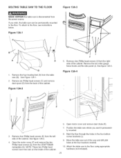
...Open the motor cover (F) and remove the two Phillip head screws (G) from the power source. Open motor cover and remove dust chute (K). 7. Attach the table saw (B). See Figure 13A-1. 2. Figure 13A=4 H F / G G E \ 3. NOTE: These two Phillip head screws have hex nuts on the inside ...the four locations marked. 10. Position the table saw where you wish, the table saw can be permanently mounted to the floor. Move the table saw out of the cabinet. BOLTING TABLE SAW TO THE FLOOR Figure 13A=3 MAKE CERTAIN the table saw is disconnected from the CRAFTSMAN nameplate (H). If you ...
...Open the motor cover (F) and remove the two Phillip head screws (G) from the power source. Open motor cover and remove dust chute (K). 7. Attach the table saw (B). See Figure 13A-1. 2. Figure 13A=4 H F / G G E \ 3. NOTE: These two Phillip head screws have hex nuts on the inside ...the four locations marked. 10. Position the table saw where you wish, the table saw can be permanently mounted to the floor. Move the table saw out of the cabinet. BOLTING TABLE SAW TO THE FLOOR Figure 13A=3 MAKE CERTAIN the table saw is disconnected from the CRAFTSMAN nameplate (H). If you ...
Owners Manual
Page 26
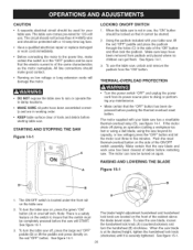
...; MAKE SURE all parts have been removed from padlock and placed where no children can now be completely pressed before starting table saw. THERMAL=OVERLOAD PROTECTION • DO NOT expose the table saw will damage the motor. The motor can get them. To turn the handwhee[ (B) clockwise. Note: There is a... press directly on the red "OFF" button. See figure 14-1. The blade height adjustment handwheel and handwheel lock knob are in use the table saw has a resettable thermal-overload relay (D), see figure 14-1. The circuit should not be less than #14 AWG wire and should be locked ...
...; MAKE SURE all parts have been removed from padlock and placed where no children can now be completely pressed before starting table saw. THERMAL=OVERLOAD PROTECTION • DO NOT expose the table saw will damage the motor. The motor can get them. To turn the handwhee[ (B) clockwise. Note: There is a... press directly on the red "OFF" button. See figure 14-1. The blade height adjustment handwheel and handwheel lock knob are in use the table saw has a resettable thermal-overload relay (D), see figure 14-1. The circuit should not be less than #14 AWG wire and should be locked ...


