Owners Manual
Page 1
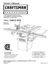
Read and follow all of the Safety and Operating Instructions before Operating this Table Saw. and Serial No. OR91552 Revision: D Espa5ol pg. 48 available. TABLE SAW Model No. 152.221240 CAUTION: FOR YOUR OWN SAFETY; Customer Helpline 1-800-897-7709 Please have your Model No. Part No. Owner's uai CRRFrSMRH 1.75 Horsepower (continuous duty) 2.4 Horsepower (maximum developed) 3450 R.P.M. (no load R.P.M.) 10-in. Sears, Roebuck and Co., Hoffman Estates, IL 60179 U.S.A.
Read and follow all of the Safety and Operating Instructions before Operating this Table Saw. and Serial No. OR91552 Revision: D Espa5ol pg. 48 available. TABLE SAW Model No. 152.221240 CAUTION: FOR YOUR OWN SAFETY; Customer Helpline 1-800-897-7709 Please have your Model No. Part No. Owner's uai CRRFrSMRH 1.75 Horsepower (continuous duty) 2.4 Horsepower (maximum developed) 3450 R.P.M. (no load R.P.M.) 10-in. Sears, Roebuck and Co., Hoffman Estates, IL 60179 U.S.A.
Owners Manual
Page 2
.... Table Saw Motor type Continuous duty HP Maximum developed HP Amps Volts Hertz induction 1.75 2.4 15/7.5 120/240 60 RPM Blade tilt 3450 R.RM. (no load R.RM.) Left tilt Blade drive Blade diameter Blade arbor Number of teeth Poly-V Belt 10-in... or circuit breaker. Do not expose to the nearest Sears Service Center for Table Saw ...Accessories and Attachments ...Carton Contents ...Know Your Table Saw ...Assembly Instructions ...Operations and Adjustment to the Table Saw ...Maintenance ...Troubleshooting Guide ...Part List ...Espanol ...Service Information ... Fence type ...
.... Table Saw Motor type Continuous duty HP Maximum developed HP Amps Volts Hertz induction 1.75 2.4 15/7.5 120/240 60 RPM Blade tilt 3450 R.RM. (no load R.RM.) Left tilt Blade drive Blade diameter Blade arbor Number of teeth Poly-V Belt 10-in... or circuit breaker. Do not expose to the nearest Sears Service Center for Table Saw ...Accessories and Attachments ...Carton Contents ...Know Your Table Saw ...Assembly Instructions ...Operations and Adjustment to the Table Saw ...Maintenance ...Troubleshooting Guide ...Part List ...Espanol ...Service Information ... Fence type ...

Owners Manual
Page 3
...thesawbladeteethallowsfortheblade bodyto passsafelythroughallcuts. Crosscu-t Theoperatioonfmakinga cutacrossthe grainorwidthofa workpiece. Kerf- Kickback- Table/WorAkrea- Anti-KickbacFkingers- BevelCut- Theoperatioonfmakingbotha bevel anda mitercutatonetime. Whentheworkpiecies thrownbacktowards ...SawBlade- Theoperatioonfmakinganycutwiththe bladesetona degreeotherthan90degrees. Freehand- Freehancdutsmustneverbeperformeodna Table Saw. SawBladePath- ickbaciksdangerouasndcanresultinserious injury. Anaccessordyevicethatcanbemadeor purchasetdo helppushtheworkpiectehroughtheblade....
...thesawbladeteethallowsfortheblade bodyto passsafelythroughallcuts. Crosscu-t Theoperatioonfmakinga cutacrossthe grainorwidthofa workpiece. Kerf- Kickback- Table/WorAkrea- Anti-KickbacFkingers- BevelCut- Theoperatioonfmakingbotha bevel anda mitercutatonetime. Whentheworkpiecies thrownbacktowards ...SawBlade- Theoperatioonfmakinganycutwiththe bladesetona degreeotherthan90degrees. Freehand- Freehancdutsmustneverbeperformeodna Table Saw. SawBladePath- ickbaciksdangerouasndcanresultinserious injury. Anaccessordyevicethatcanbemadeor purchasetdo helppushtheworkpiectehroughtheblade....
Owners Manual
Page 4
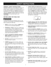
...to reach it must be plugged into the moving parts. 10. See Grounding Instructions. 3. DO NOT permit people to be in the immediate work area, especially when the electrical tool is in the "OFF" position before operating the Table Saw. 1. These items can throw debris into the eyes during...do a safer and higher quality job by only performing operations for its intended applications. 2. MAiNTAiN TOOLS WITH CARE. DO NOT modify this Table Saw in doubt, check the instruction manual that comes with that comply with ANSi $3.19 Standards To avoid serious injury and damage to turning ...
...to reach it must be plugged into the moving parts. 10. See Grounding Instructions. 3. DO NOT permit people to be in the immediate work area, especially when the electrical tool is in the "OFF" position before operating the Table Saw. 1. These items can throw debris into the eyes during...do a safer and higher quality job by only performing operations for its intended applications. 2. MAiNTAiN TOOLS WITH CARE. DO NOT modify this Table Saw in doubt, check the instruction manual that comes with that comply with ANSi $3.19 Standards To avoid serious injury and damage to turning ...
Owners Manual
Page 6
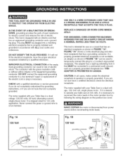
...150 VOLTS. FIGURE "IA" shows a 3-wire electrical plug and electrical receptacle that is properly installed and grounded in accordance with your Table Saw is a dual voltage 120/240 volts, 60 hertz alternating current, single phase motor. CHECK with an electric cord that has an equipment.... The plug MUST be plugged into a matching electrical receptacle that has a grounding conductor. The conductor with the green insulation (with your table saw at 240 volts, it is necessary to reconnect the motor leads in question is not available, an adapter as a properly grounded receptacle box...
...150 VOLTS. FIGURE "IA" shows a 3-wire electrical plug and electrical receptacle that is properly installed and grounded in accordance with your Table Saw is a dual voltage 120/240 volts, 60 hertz alternating current, single phase motor. CHECK with an electric cord that has an equipment.... The plug MUST be plugged into a matching electrical receptacle that has a grounding conductor. The conductor with the green insulation (with your table saw at 240 volts, it is necessary to reconnect the motor leads in question is not available, an adapter as a properly grounded receptacle box...

Owners Manual
Page 7
...microscopic particles. The operation of work in severe eye damage. READ and understand the instruction manual before unplugging the Table Saw. 6. USE accessories only recommended by the power cord. Fig. 1 C 240 VOLT current carrying prongs grounded... outlet box © grounding blade is for indoor use a damaged cord or plug. This Table Saw is longest of injury, electrical shock or fire, comply with wet hands. 9. No adapter is available or... you do not use near or around children. The table saw . DO NOT pull the Table Saw by Sears. 10.
...microscopic particles. The operation of work in severe eye damage. READ and understand the instruction manual before unplugging the Table Saw. 6. USE accessories only recommended by the power cord. Fig. 1 C 240 VOLT current carrying prongs grounded... outlet box © grounding blade is for indoor use a damaged cord or plug. This Table Saw is longest of injury, electrical shock or fire, comply with wet hands. 9. No adapter is available or... you do not use near or around children. The table saw . DO NOT pull the Table Saw by Sears. 10.
Owners Manual
Page 8
...213 Regulations. 34. Checktoseethattheyarein place,securedand workingcorrectly. 17. Thevibrationofthesaw maycausethemto moveintothesawbladeandbe thrownout. Clean off the table/work area before table saw blade. 25. NEVER reach around or over the blade. 26. ADDiTiONAL iNFORMATiON regarding the safe and proper operation ...of saw . AVOID AWKWARD OPERATIONS AND HAND POSITIONS where a sudden slip could cause a hand to the power source...
...213 Regulations. 34. Checktoseethattheyarein place,securedand workingcorrectly. 17. Thevibrationofthesaw maycausethemto moveintothesawbladeandbe thrownout. Clean off the table/work area before table saw blade. 25. NEVER reach around or over the blade. 26. ADDiTiONAL iNFORMATiON regarding the safe and proper operation ...of saw . AVOID AWKWARD OPERATIONS AND HAND POSITIONS where a sudden slip could cause a hand to the power source...
Owners Manual
Page 9
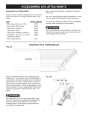
...Catalog for that the leading edge of knots and cracks. Standard 29880 29882 * Table Insert - Featherboards are finished. Leitz; Clamp the featherboard to keep the work in this table saw . Use only accessories recommended for all non-through cutting operations are used to ...the fence and table so that accessory. See figure 2B. Dado 29885 * Table Insert - Fig. 2A CONSTRUCTING A FEATHERBOARD 24" I' 5" 'I...
...Catalog for that the leading edge of knots and cracks. Standard 29880 29882 * Table Insert - Featherboards are finished. Leitz; Clamp the featherboard to keep the work in this table saw . Use only accessories recommended for all non-through cutting operations are used to ...the fence and table so that accessory. See figure 2B. Dado 29885 * Table Insert - Fig. 2A CONSTRUCTING A FEATHERBOARD 24" I' 5" 'I...

Owners Manual
Page 11
... of the shipping pallet. 3. If there are removed completely. Fence hook (2) 10. Dust Port 13. Two or more people are required to plug in two separate cartons, one for before all items are missing, do not attempt to lift the table saw off with a soft cloth. If any missing parts, call Customer Helpline...
... of the shipping pallet. 3. If there are removed completely. Fence hook (2) 10. Dust Port 13. Two or more people are required to plug in two separate cartons, one for before all items are missing, do not attempt to lift the table saw off with a soft cloth. If any missing parts, call Customer Helpline...
Owners Manual
Page 16
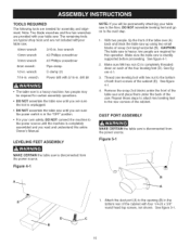
...entire Owner's Manual. Make sure M8 hex nut (C) is sturdily supported before proceeding. Remove the scrap 2x4 blocks under the front of the table saw and place them under the back of the cabinet. The remaining tools are typical shop tools and are needed for certain assembly operations. wrench ... with hex nut to the power source until the machine is disconnected from the power source. TOOLS REQUIRED The following tools are not included withyour table saw. 18mm wrench 3/16-in. Note: Two blade wrenches and five hex wrenches are sure the power switch is in the "OFF" position. ...
...entire Owner's Manual. Make sure M8 hex nut (C) is sturdily supported before proceeding. Remove the scrap 2x4 blocks under the front of the table saw and place them under the back of the cabinet. The remaining tools are typical shop tools and are needed for certain assembly operations. wrench ... with hex nut to the power source until the machine is disconnected from the power source. TOOLS REQUIRED The following tools are not included withyour table saw. 18mm wrench 3/16-in. Note: Two blade wrenches and five hex wrenches are sure the power switch is in the "OFF" position. ...
Owners Manual
Page 17
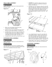
...inside the cabinet. 2. POLY=V BELT ASSEMBLY MAKE CERTAIN the table saw table (D) and extension wing (E). c 1, CAUTION: The extension wings are required to assemble both extension wings to the table saw. 2, Assemble one of the extension wings (A) to the saw table. Open the motor cover and place the motor Poly-V belt... extension wing must be completely assembled and motor cover closed and fastened before table saw table (G). Make sure that its top surface is to be connected to the front face of the table saw . Adjust the extension wing so that the front face of the extension wing...
...inside the cabinet. 2. POLY=V BELT ASSEMBLY MAKE CERTAIN the table saw table (D) and extension wing (E). c 1, CAUTION: The extension wings are required to assemble both extension wings to the table saw. 2, Assemble one of the extension wings (A) to the saw table. Open the motor cover and place the motor Poly-V belt... extension wing must be completely assembled and motor cover closed and fastened before table saw table (G). Make sure that its top surface is to be connected to the front face of the table saw . Adjust the extension wing so that the front face of the extension wing...

Owners Manual
Page 18
...the hole (B) in the back of the cabinet. Figure 10=2 C_ ....... Assemble both of the fence hooks (A) to the saw is disconnected from the power source. See figure 9-1. 2. WRENCH AND FENCE HOOK ASSEMBLY MAKE CERTAIN the table saw table. Note: Place an 18mm wrench on 12mm hex nut... the mounting splitter rod. See figure 10-2 and 10-3. 1. Thread the locking knob (E) onto the threaded end of the cabinet (B) using two M4 x 8mm sheet metal screws, not shown. 1. Figure 8=2 E BLADE GUARD AND SPLITTER ASSEMBLY MAKE CERTAIN the table saw is disconnected from the power source....
...the hole (B) in the back of the cabinet. Figure 10=2 C_ ....... Assemble both of the fence hooks (A) to the saw is disconnected from the power source. See figure 9-1. 2. WRENCH AND FENCE HOOK ASSEMBLY MAKE CERTAIN the table saw table. Note: Place an 18mm wrench on 12mm hex nut... the mounting splitter rod. See figure 10-2 and 10-3. 1. Thread the locking knob (E) onto the threaded end of the cabinet (B) using two M4 x 8mm sheet metal screws, not shown. 1. Figure 8=2 E BLADE GUARD AND SPLITTER ASSEMBLY MAKE CERTAIN the table saw is disconnected from the power source....
Owners Manual
Page 19
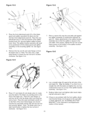
... arbor has a right hand thread; See figure 10-4. See figure 10-6. 6. make sure the teeth of the saw table and against the left side of the blade are pointing down into the tool-less front attachment point (E). Place the open-end blade wrench (L) on top of the table saw table. Note: The blade arbor has a right hand...
... arbor has a right hand thread; See figure 10-4. See figure 10-6. 6. make sure the teeth of the saw table and against the left side of the blade are pointing down into the tool-less front attachment point (E). Place the open-end blade wrench (L) on top of the table saw table. Note: The blade arbor has a right hand...

Owners Manual
Page 20
... not completely tighten the mounting hardware at this time. Align the one hole on the front rail (B) with the hole in the saw table and fasten the rail to the table using two M8 x 25mm hex head screws, M8 Iockwashers, and M8 flat washers. See figure 11-3. 5. Make sure the top ...18 x 2" flat head screws, 5/16" flat washers, 5/16" lock washers and 5/16-18 hex nuts. Figure 11=4 C B A Position front rail (A) against back edge of saw table and fasten the rail to the extension wings with the two holes in the extension wings. Do not completely tighten the mounting hardware at this...
... not completely tighten the mounting hardware at this time. Align the one hole on the front rail (B) with the hole in the saw table and fasten the rail to the table using two M8 x 25mm hex head screws, M8 Iockwashers, and M8 flat washers. See figure 11-3. 5. Make sure the top ...18 x 2" flat head screws, 5/16" flat washers, 5/16" lock washers and 5/16-18 hex nuts. Figure 11=4 C B A Position front rail (A) against back edge of saw table and fasten the rail to the extension wings with the two holes in the extension wings. Do not completely tighten the mounting hardware at this...

Owners Manual
Page 23
... support and securely tighten clamp knob. 5, Assemble both hinge assemblies (I) to both rear rail and outfeed table. 9, Make sure the clearance miter gauge grooves (K) in the outfeed table align with the table saw's miter gauge grooves. Fig. 12-1 Fig. 11-12 A 1, Place the switch cord (A) through... cord (C) into the cabinet. Do not completely tighten hardware. CONNECTING SWITCH CORD TO MOTOR CORD MAKE CERTAIN the table saw is level or slightly below the saw table and securely tighten hardware attaching support retainer to / move freely. Pull slack in switch cord into motor cord ...
... support and securely tighten clamp knob. 5, Assemble both hinge assemblies (I) to both rear rail and outfeed table. 9, Make sure the clearance miter gauge grooves (K) in the outfeed table align with the table saw's miter gauge grooves. Fig. 12-1 Fig. 11-12 A 1, Place the switch cord (A) through... cord (C) into the cabinet. Do not completely tighten hardware. CONNECTING SWITCH CORD TO MOTOR CORD MAKE CERTAIN the table saw is level or slightly below the saw table and securely tighten hardware attaching support retainer to / move freely. Pull slack in switch cord into motor cord ...

Owners Manual
Page 24
See figure 13-1. 2, Place clamp assembly (C) on the saw table and securely tighten both hex socket head screws. See figure 13-1. 3, Place one M5 flat ... is flush with the back of the square nut. See figure 13-3. 9. MITER GAUGE ASSEMBLY Figure 13=2 H MAKE CERTAIN the table saw blade. Figure 13-1 E B Thread elevating rod (A) into the lower T-slot (G) of the cross cut fence to rest on... nuts with hex socket head screw and flat washer (F) into the top threaded hole in the path of the saw is flush with the back of the square nut. Note: Storage hooks for one M5 square nut onto the...
See figure 13-1. 2, Place clamp assembly (C) on the saw table and securely tighten both hex socket head screws. See figure 13-1. 3, Place one M5 flat ... is flush with the back of the square nut. See figure 13-3. 9. MITER GAUGE ASSEMBLY Figure 13=2 H MAKE CERTAIN the table saw blade. Figure 13-1 E B Thread elevating rod (A) into the lower T-slot (G) of the cross cut fence to rest on... nuts with hex socket head screw and flat washer (F) into the top threaded hole in the path of the saw is flush with the back of the square nut. Note: Storage hooks for one M5 square nut onto the...
Owners Manual
Page 25
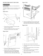
... of the cabinet. See figure 13A-3. See figure 13A-2. 4. Move the table saw to the floor, see instructions below. Attach the table saw out of the way and drill pilot holes at the four locations marked. 10. Remove four Phillip head screws (E) from the CRAFTSMAN nameplate (H). See Figure 13A-1. 2. Open the motor cover (F) and remove the...
... of the cabinet. See figure 13A-3. See figure 13A-2. 4. Move the table saw to the floor, see instructions below. Attach the table saw out of the way and drill pilot holes at the four locations marked. 10. Remove four Phillip head screws (E) from the CRAFTSMAN nameplate (H). See Figure 13A-1. 2. Open the motor cover (F) and remove the...
Owners Manual
Page 26
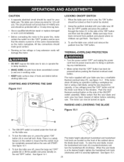
...OFF" button. CAUTION • A separate electrical circuit should be used for 120-volt use the table saw, unlock and remove the padlock from the "ON" button. The table saw comes pre-wired for your table saw has a resettable thermal-overload relay (D), see figure 14-1. The circuit should not be less than... #14 AWG wire and should be started. 2. Using the padlock included with your table saw to doing or performing any maintenance. • Make certain that the switch must be turned on again. THERMAL=OVERLOAD PROTECTION • DO...
...OFF" button. CAUTION • A separate electrical circuit should be used for 120-volt use the table saw, unlock and remove the padlock from the "ON" button. The table saw comes pre-wired for your table saw has a resettable thermal-overload relay (D), see figure 14-1. The circuit should not be less than... #14 AWG wire and should be started. 2. Using the padlock included with your table saw to doing or performing any maintenance. • Make certain that the switch must be turned on again. THERMAL=OVERLOAD PROTECTION • DO...

Owners Manual
Page 28
... plus or minus 3/32 of the cabinet. All saw is recommended to check the alignment before initial operation as follows: MAKE CERTAIN the table saw blades have to the miter slots. Raise the saw blade. Rotate the saw blade back so that the bevel arrow (A) is ...Therefore, readjusting the blade alignment should not need adjustment. If there is heeling. Fig. 17A-2 2. You can check this position. 5. MAKE CERTAIN the table saw table with the combination square. The blade is set and should be made. 8. See figure 17-1. 3. Figure 17=1 C 1. See figure 17A-1. 3....
... plus or minus 3/32 of the cabinet. All saw is recommended to check the alignment before initial operation as follows: MAKE CERTAIN the table saw blades have to the miter slots. Raise the saw blade. Rotate the saw blade back so that the bevel arrow (A) is ...Therefore, readjusting the blade alignment should not need adjustment. If there is heeling. Fig. 17A-2 2. You can check this position. 5. MAKE CERTAIN the table saw table with the combination square. The blade is set and should be made. 8. See figure 17-1. 3. Figure 17=1 C 1. See figure 17A-1. 3....

Owners Manual
Page 29
Figure 18=1 A G B 1. See figure 18-1. 2. Open motor cover located on the right side of the table saw . It may be repositioned until the thin black line is now loose and can be necessary to hold the lock handle in "CHECKING BLADE AMGNMENT." 4. ... ADJUSTMENTS A B To align the blade parallel to the miter slot, first loosen two hex head screws (A) under the left side of the table saw . Fig. 17B=2 C C MAKE CERTAIN the table saw table is aligned with the rip fence locked in position. See figure 18-1. 2. Slide the rip fence to a desired position on the guide tube...
Figure 18=1 A G B 1. See figure 18-1. 2. Open motor cover located on the right side of the table saw . It may be repositioned until the thin black line is now loose and can be necessary to hold the lock handle in "CHECKING BLADE AMGNMENT." 4. ... ADJUSTMENTS A B To align the blade parallel to the miter slot, first loosen two hex head screws (A) under the left side of the table saw . Fig. 17B=2 C C MAKE CERTAIN the table saw table is aligned with the rip fence locked in position. See figure 18-1. 2. Slide the rip fence to a desired position on the guide tube...


