
Setup Manual
Page 2
Table of Contents Chapter 1: Introduction 1 1.1 Before You Start 1 1.2 Package Checklist 1 1.3 Motherboard Features 2 1.4 Rear Panel Connectors 3 1.5 Motherboard Layout 4 Chapter 2: Hardware Installation 5 2.1 Installing Central Processing Unit (CPU 5 2.2 FAN Headers 6 2.3 Installing System Memory 8 2.4 Connectors and Slots 10 Chapter 3: Headers & Jumpers Setup 12 3.1 How to Setup Jumpers 12 3.2 Detail Settings 12 Chapter 4: NVIDIA RAID ...
Table of Contents Chapter 1: Introduction 1 1.1 Before You Start 1 1.2 Package Checklist 1 1.3 Motherboard Features 2 1.4 Rear Panel Connectors 3 1.5 Motherboard Layout 4 Chapter 2: Hardware Installation 5 2.1 Installing Central Processing Unit (CPU 5 2.2 FAN Headers 6 2.3 Installing System Memory 8 2.4 Connectors and Slots 10 Chapter 3: Headers & Jumpers Setup 12 3.1 How to Setup Jumpers 12 3.2 Detail Settings 12 Chapter 4: NVIDIA RAID ...
Setup Manual
Page 4
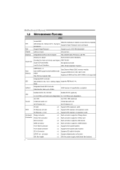
...x1 Supports front panel facilities Front Audio Connector x1 Supports front panel audio function CD-in Connector x1 Supports CD audio-in GeForce 6100 Chipset Max Shared Video Memory is not supported Integrated IDE Controller IDE Ultra DMA 33 / 66 / 100 / 133 Bus ... transfer rates up to 3 Gb/s. SATA Version 2.0 specification compliant. Motherboard Manual 1.3 MOTHERBOARD FEATURES SPEC Socket AM2 AMD 64 Architecture enables 32 and 64 bit computing CPU AMD Athlon 64 / Athlon 64 FX / Sempron Supports Hyper Transport and Cool=n=Quiet processors FSB Support HyperTransport ...
...x1 Supports front panel facilities Front Audio Connector x1 Supports front panel audio function CD-in Connector x1 Supports CD audio-in GeForce 6100 Chipset Max Shared Video Memory is not supported Integrated IDE Controller IDE Ultra DMA 33 / 66 / 100 / 133 Bus ... transfer rates up to 3 Gb/s. SATA Version 2.0 specification compliant. Motherboard Manual 1.3 MOTHERBOARD FEATURES SPEC Socket AM2 AMD 64 Architecture enables 32 and 64 bit computing CPU AMD Athlon 64 / Athlon 64 FX / Sempron Supports Hyper Transport and Cool=n=Quiet processors FSB Support HyperTransport ...
Setup Manual
Page 7
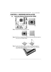
Step 3: Look for the white triangle on socket, and the gold triangle on CPU should point forwards this white triangle. TForce 6100 AM2 CHAPTER 2: HARDWARE INSTALLATION 2.1 INSTALLING CENTRAL PROCESSING UNIT (CPU) Step 1: Remove the socket protection cap. Step 2: Pull the lever toward direction A from the socket and then raise the lever up to a 90-degree angle. The CPU will fit only in the correct orientation. 5
Step 3: Look for the white triangle on socket, and the gold triangle on CPU should point forwards this white triangle. TForce 6100 AM2 CHAPTER 2: HARDWARE INSTALLATION 2.1 INSTALLING CENTRAL PROCESSING UNIT (CPU) Step 1: Remove the socket protection cap. Step 2: Pull the lever toward direction A from the socket and then raise the lever up to a 90-degree angle. The CPU will fit only in the correct orientation. 5
Setup Manual
Page 8
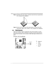
... power cable to complete the installation. Motherboard Manual Step 4: Hold the CPU down firmly, and then close the lever toward direct B to the JCFAN1. The fan cable and connector may be different according to pin#1. This completes ...the installation. 2.2 FAN HEADERS These fan headers support cooling-fans built in the computer. JCFAN1: CPU Fan Header JCFAN1 4 1 Pin Assignment 1 Ground 2 +12V 3 FAN RPM rate sense 4 Smart Fan Control 6 Step 5: Put the CPU Fan on the CPU and buckle it. Connect the fan cable to the connector while matching the black wire...
... power cable to complete the installation. Motherboard Manual Step 4: Hold the CPU down firmly, and then close the lever toward direct B to the JCFAN1. The fan cable and connector may be different according to pin#1. This completes ...the installation. 2.2 FAN HEADERS These fan headers support cooling-fans built in the computer. JCFAN1: CPU Fan Header JCFAN1 4 1 Pin Assignment 1 Ground 2 +12V 3 FAN RPM rate sense 4 Smart Fan Control 6 Step 5: Put the CPU Fan on the CPU and buckle it. Connect the fan cable to the connector while matching the black wire...
Setup Manual
Page 16
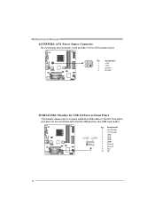
JUSB2 JUSB3 4 USB- 2 10 5 USB+ 6 USB+ 7 Ground 1 9 8 Ground 9 Key 10 NC 14 Motherboard Manual JATXPWR2: ATX Power Source Connector By connecting this connector, it will provide +12V to CPU power circuit. 3 2 Pin 1 Assignment +12V 4 1 2 +12V 3 Ground 4 Ground JUSB2/JUSB3: Headers for USB 2.0 Ports at Front Panel This header allows user to connect additional USB cable on the PC front panel, and also can be connected with internal USB devices, like USB card reader. Pin Assignment 1 +5V (fused) 2 +5V (fused) 3 USB-
JUSB2 JUSB3 4 USB- 2 10 5 USB+ 6 USB+ 7 Ground 1 9 8 Ground 9 Key 10 NC 14 Motherboard Manual JATXPWR2: ATX Power Source Connector By connecting this connector, it will provide +12V to CPU power circuit. 3 2 Pin 1 Assignment +12V 4 1 2 +12V 3 Ground 4 Ground JUSB2/JUSB3: Headers for USB 2.0 Ports at Front Panel This header allows user to connect additional USB cable on the PC front panel, and also can be connected with internal USB devices, like USB card reader. Pin Assignment 1 +5V (fused) 2 +5V (fused) 3 USB-
Setup Manual
Page 22
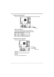
PWRSW1 PWRSW1: This is an on diagnostics. Motherboard Manual On-Board LED Indicators There are 2 on -board Power On/Off button. Please refer to show system status. On-Board Buttons (optional) There are 2 LED indicators on the motherboard to the table below for different messages: LED_D1 ON ON OFF OFF LED_D2 ON OFF ON OFF Message Norm al Mem ory Error VGA Error Abnormal: CPU / Chipset error. RSTSW2 20 LED_D1 LED_D2 LED_D1 and LED_D2: These 2 LED indicate system power on -board Reset button. RSTSW2: This is an on -board buttons.
PWRSW1 PWRSW1: This is an on diagnostics. Motherboard Manual On-Board LED Indicators There are 2 on -board Power On/Off button. Please refer to show system status. On-Board Buttons (optional) There are 2 LED indicators on the motherboard to the table below for different messages: LED_D1 ON ON OFF OFF LED_D2 ON OFF ON OFF Message Norm al Mem ory Error VGA Error Abnormal: CPU / Chipset error. RSTSW2 20 LED_D1 LED_D2 LED_D1 and LED_D2: These 2 LED indicate system power on -board Reset button. RSTSW2: This is an on -board buttons.
Setup Manual
Page 28
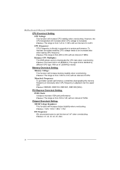
...: The range is from 1.2V to 1.725V, with an interval of 0.0.25V. Choices: The range is increased. CPU Frequency: CPU Frequency is decided by different CPU type. Choices: 1.52V, 1.60V, 1.68V, 1.76V. HT Frequency: We recommend users to be increased also when raising... The MOS allows users to increase VGA card performance. However, the CPU temperature will increase CPU stability when overclocking. With an x1 (200MHz) interval. Motherboard Manual CPU Overclock Setting: CPU Voltage: This function will increase when CPU voltage is from 1.85V to 2.0V, with an interval of 0.05V...
...: The range is from 1.2V to 1.725V, with an interval of 0.0.25V. Choices: The range is increased. CPU Frequency: CPU Frequency is decided by different CPU type. Choices: 1.52V, 1.60V, 1.68V, 1.76V. HT Frequency: We recommend users to be increased also when raising... The MOS allows users to increase VGA card performance. However, the CPU temperature will increase CPU stability when overclocking. With an x1 (200MHz) interval. Motherboard Manual CPU Overclock Setting: CPU Voltage: This function will increase when CPU voltage is from 1.85V to 2.0V, with an interval of 0.05V...
Setup Manual
Page 30
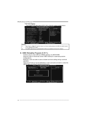
... able to name the CMOS data according to save different CMOS settings into BIOS-ROM. the difference will raise about 25%~30% of AMD CPU perform above overclock setting ideally; B. Notices: 1. Motherboard Manual V12 Tech Engine: This setting will be based on the selected... CPU model. 2. Users are able to personal preference. 28 CMOS Reloading Program (C.R.P.): It allows users to reload any saved CMOS setting for this A.O.S. Moreover, users ...
... able to name the CMOS data according to save different CMOS settings into BIOS-ROM. the difference will raise about 25%~30% of AMD CPU perform above overclock setting ideally; B. Notices: 1. Motherboard Manual V12 Tech Engine: This setting will be based on the selected... CPU model. 2. Users are able to personal preference. 28 CMOS Reloading Program (C.R.P.): It allows users to reload any saved CMOS setting for this A.O.S. Moreover, users ...
Setup Manual
Page 33
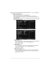
... an interval of 1℃. TForce 6100 AM2 F. Choices: 16℃ (default). The range is from 0℃~127℃, with an interval of 1℃. When enabling Smart Fan function, Fan speed is under Full Speed. CPU Fan Full speed When CPU temperature arrives to the set value, the CPU fan will work when CPU temperature arrives to control...
... an interval of 1℃. TForce 6100 AM2 F. Choices: 16℃ (default). The range is from 0℃~127℃, with an interval of 1℃. When enabling Smart Fan function, Fan speed is under Full Speed. CPU Fan Full speed When CPU temperature arrives to the set value, the CPU fan will work when CPU temperature arrives to control...
Setup Manual
Page 34
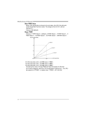
Increasing the value of slope PWM will work under Smart Fan Function mode. As in above diagram, when the CPU temperature reaches 60℃, the CPU fan speed for 3 PWM/℃ is 1 PWM/℃. Slope PWM Choices: 1 PWM Value/℃ (default), 2 PWM Value/℃, 4 PWM Value/℃, 8 PWM Value/℃, 16 ...PWM Value/℃, 32 PWM Value/℃, 64PWM Value/℃. S1: CPU temperature is 60℃, and PWM value is higher than 1 PWM/℃ (S1 The range is 3 PWM/℃. S3...
Increasing the value of slope PWM will work under Smart Fan Function mode. As in above diagram, when the CPU temperature reaches 60℃, the CPU fan speed for 3 PWM/℃ is 1 PWM/℃. Slope PWM Choices: 1 PWM Value/℃ (default), 2 PWM Value/℃, 4 PWM Value/℃, 8 PWM Value/℃, 16 ...PWM Value/℃, 32 PWM Value/℃, 64PWM Value/℃. S1: CPU temperature is 60℃, and PWM value is higher than 1 PWM/℃ (S1 The range is 3 PWM/℃. S3...
Setup Manual
Page 36
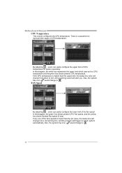
.... In this diagram, the green line shows present CPU Fan speed, and the yellow line shows System Fan speed (if any one of CPU temperature. Also, the system tray icon would change from green to . If the CPU temperature is lower than the upper limit, the status... limit of the fan speed. If any ). Motherboard Manual CPU Temperature This column configures the CPU temperature. By adjusting , users can easily configure the lower limit of CPU temperature for CPU temperature and the green line shows present CPU temperature. In this diagram, the white line represents the upper...
.... In this diagram, the green line shows present CPU Fan speed, and the yellow line shows System Fan speed (if any one of CPU temperature. Also, the system tray icon would change from green to . If the CPU temperature is lower than the upper limit, the status... limit of the fan speed. If any ). Motherboard Manual CPU Temperature This column configures the CPU temperature. By adjusting , users can easily configure the lower limit of CPU temperature for CPU temperature and the green line shows present CPU temperature. In this diagram, the white line represents the upper...

Setup Manual
Page 37
... voltage. If battery voltage is higher or lower than the set value, the status line will change to . If CPU voltage is only for present status reference. 35 Users can set value, the status line will change into a red warning line, and a warning ... higher or lower than the set the upper and lower limit by adjusting to a red warning line, and a warning sound will alert you . CPU/Battery Voltage TForce 6100 AM2 i. Reference data This column represents the status of battery voltage. VBAT This item displays the CMOS battery voltage, represented by a light blue line. ...
... voltage. If battery voltage is higher or lower than the set value, the status line will change to . If CPU voltage is only for present status reference. 35 Users can set value, the status line will change into a red warning line, and a warning ... higher or lower than the set the upper and lower limit by adjusting to a red warning line, and a warning sound will alert you . CPU/Battery Voltage TForce 6100 AM2 i. Reference data This column represents the status of battery voltage. VBAT This item displays the CMOS battery voltage, represented by a light blue line. ...
Setup Manual
Page 38
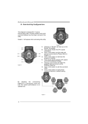
...Graphic 2 Graphic 1 A. Clicking on this button and the utility will lead you to Graphic 3). This column shows present CPU speed and overclocking percentage. Graphic 3 36 B. Click on "Biostar" will pop-up . E. G. Graphic 1 will make the program start up as soon as the Windows starts up ...4 sub-screens (Please refers to the Biostar Homepage. D. H. By adjusting the overclocking features in 4 sub-screens, users can tune the system performance to default setting. This column shows the CPU speed information. Click on this button to minimize this ...
...Graphic 2 Graphic 1 A. Clicking on this button and the utility will lead you to Graphic 3). This column shows present CPU speed and overclocking percentage. Graphic 3 36 B. Click on "Biostar" will pop-up . E. G. Graphic 1 will make the program start up as soon as the Windows starts up ...4 sub-screens (Please refers to the Biostar Homepage. D. H. By adjusting the overclocking features in 4 sub-screens, users can tune the system performance to default setting. This column shows the CPU speed information. Click on this button to minimize this ...
Setup Manual
Page 39
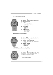
... Range: 4~25. AGP/PCI-Express Overclocking Setting: By adjusting can configure two items for CPU overclocking. Memory Voltage Range: 1.8V~2.8V. Memory Overclocking Settings: By adjusting can configure VGA card overclocking. And this function helps to increase VGA card performance. CPU Overclocking Settings: TForce 6100 AM2 By adjusting can configure three items for Memory overclocking.
... Range: 4~25. AGP/PCI-Express Overclocking Setting: By adjusting can configure two items for CPU overclocking. Memory Voltage Range: 1.8V~2.8V. Memory Overclocking Settings: By adjusting can configure VGA card overclocking. And this function helps to increase VGA card performance. CPU Overclocking Settings: TForce 6100 AM2 By adjusting can configure three items for Memory overclocking.
Setup Manual
Page 41
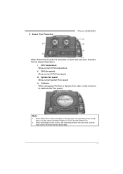
ii. iii. Note: 1. Smart Fan Function TForce 6100 AM2 When Smart Fan Function is done, the calibrating window will auto-close, and the main screen will pop-up to illustrate the fan speed information. ... Fan Function activates for the first time, this button to get upper and lower limitation of CPU Fan and System Fan. 2. CPU Temperature: Show current CPU temperature. iv. CPU Fan speed: Show current CPU Fan speed. Calibrate: When changing CPU Fan or System Fan, click on this calibrate function would auto-run to re-calibrate the...
ii. iii. Note: 1. Smart Fan Function TForce 6100 AM2 When Smart Fan Function is done, the calibrating window will auto-close, and the main screen will pop-up to illustrate the fan speed information. ... Fan Function activates for the first time, this button to get upper and lower limitation of CPU Fan and System Fan. 2. CPU Temperature: Show current CPU temperature. iv. CPU Fan speed: Show current CPU Fan speed. Calibrate: When changing CPU Fan or System Fan, click on this calibrate function would auto-run to re-calibrate the...
Setup Manual
Page 42
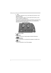
... a screen as below would pop-up , the Smart Fan Function is lit up . Motherboard Manual v. There will be pulling-meter besides the CPU Fan and System Fan, the CPU Fan and the System Fan speed can be adjusted by adjusting the Cursor Up or Down. Program Tool Bar: z About: Click on this...
... a screen as below would pop-up , the Smart Fan Function is lit up . Motherboard Manual v. There will be pulling-meter besides the CPU Fan and System Fan, the CPU Fan and the System Fan speed can be adjusted by adjusting the Cursor Up or Down. Program Tool Bar: z About: Click on this...
Setup Manual
Page 45
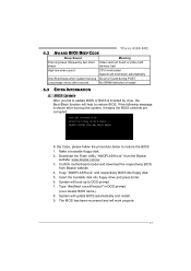
Make a bootable floppy disk. 2. Confirm motherboard model and download the respectively BIOS from the Biostar website: www.biostar.com.tw 3. TForce 6100 AM2 6.2 AWARD BIOS BEEP CODE Beep Sound Meaning One long beep followed by virus, the Boot-Block function will shut down ...Enter. 6. System will work properly. 43 Download the Flash Utility "AWDFLASH.exe" from Biostar website. 4. System will boot-up No error found or video card beeps memory bad High-low siren sound CPU overheated System will help to restore BIOS. In this Case, please follow the procedure ...
Make a bootable floppy disk. 2. Confirm motherboard model and download the respectively BIOS from the Biostar website: www.biostar.com.tw 3. TForce 6100 AM2 6.2 AWARD BIOS BEEP CODE Beep Sound Meaning One long beep followed by virus, the Boot-Block function will shut down ...Enter. 6. System will work properly. 43 Download the Flash Utility "AWDFLASH.exe" from Biostar website. 4. System will boot-up No error found or video card beeps memory bad High-low siren sound CPU overheated System will help to restore BIOS. In this Case, please follow the procedure ...
Setup Manual
Page 46
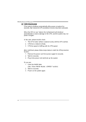
...up the system. Power on system for seconds. 3. CPU fan speed is over heated, the motherboard will shutdown automatically to relief the CPU protection function. 1. Wait for seconds. 2. Wait for seconds, that means the CPU protection function has been activated. Clear the CMOS data.... (See "Close CMOS Header: JCMOS1" section) 2. CPU Overheated If the system shutdown automatically after...
...up the system. Power on system for seconds. 3. CPU fan speed is over heated, the motherboard will shutdown automatically to relief the CPU protection function. 1. Wait for seconds. 2. Wait for seconds, that means the CPU protection function has been activated. Clear the CMOS data.... (See "Close CMOS Header: JCMOS1" section) 2. CPU Overheated If the system shutdown automatically after...
Setup Manual
Page 68
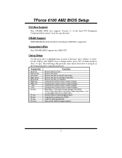
Keystroke Up arrow Down arrow Left arrow Right arrow Move Enter PgUp key PgDn key + Key - TForce 6100 AM2 BIOS Setup PCI Bus Support This AWARD BIOS also supports Version 2.1 of the place, press to select, use the and keys to change entries, press ... keys Load previous values from CMOS Load the optimized defaults Save all the CMOS changes and exit 2 Supported CPUs This AWARD BIOS supports the AMD CPU. DRAM Support DDR SDRAM (Double Data Rate Synchronous DRAM) is supported. Using Setup Use the arrow keys to quit.
Keystroke Up arrow Down arrow Left arrow Right arrow Move Enter PgUp key PgDn key + Key - TForce 6100 AM2 BIOS Setup PCI Bus Support This AWARD BIOS also supports Version 2.1 of the place, press to select, use the and keys to change entries, press ... keys Load previous values from CMOS Load the optimized defaults Save all the CMOS changes and exit 2 Supported CPUs This AWARD BIOS supports the AMD CPU. DRAM Support DDR SDRAM (Double Data Rate Synchronous DRAM) is supported. Using Setup Use the arrow keys to quit.
Setup Manual
Page 70
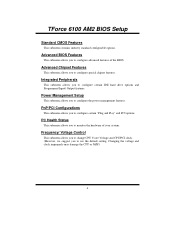
... options. PnP/PCI Configurations This submenu allows you to configure certain IDE hard drive options and Programmed Input/ Output features. TForce 6100 AM2 BIOS Setup Standard CMOS Features This submenu contains industry standard configurable options. Advanced Chipset Features This submenu allows you to configure...you to use the default setting. Changing the voltage and clock improperly may damage the CPU or M/B!) 4 Frequency/ Voltage Control This submenu allows you to change CPU Vcore Voltage and CPU/PCI clock. (However, we suggest you to monitor the hardware of the BIOS.
... options. PnP/PCI Configurations This submenu allows you to configure certain IDE hard drive options and Programmed Input/ Output features. TForce 6100 AM2 BIOS Setup Standard CMOS Features This submenu contains industry standard configurable options. Advanced Chipset Features This submenu allows you to configure...you to use the default setting. Changing the voltage and clock improperly may damage the CPU or M/B!) 4 Frequency/ Voltage Control This submenu allows you to change CPU Vcore Voltage and CPU/PCI clock. (However, we suggest you to monitor the hardware of the BIOS.


