
Setup Manual
Page 2
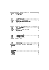
... 1.4 Rear Panel Connectors 3 1.5 Motherboard Layout 4 Chapter 2: Hardware Installation 5 2.1 Installing Central Processing Unit (CPU 5 2.2 FAN Headers 6 2.3 Installing System Memory 8 2.4 Connectors and Slots 10 Chapter 3: Headers & Jumpers Setup 12 3.1 How to Setup Jumpers 12 3.2 Detail Settings 12 Chapter 4: NVIDIA RAID Functions 22 4.1 Operation System 22 4.2 Raid Arrays 22 4.3 How RAID Works 22 CHAPTER 5: OverClock Quick Guide 23 5.1: T-Power Introduction 24 5.2: T-Power BIOS Feature 25 5.3 T-Power Windows Feature 33 Chapter 6: Useful Help...
... 1.4 Rear Panel Connectors 3 1.5 Motherboard Layout 4 Chapter 2: Hardware Installation 5 2.1 Installing Central Processing Unit (CPU 5 2.2 FAN Headers 6 2.3 Installing System Memory 8 2.4 Connectors and Slots 10 Chapter 3: Headers & Jumpers Setup 12 3.1 How to Setup Jumpers 12 3.2 Detail Settings 12 Chapter 4: NVIDIA RAID Functions 22 4.1 Operation System 22 4.2 Raid Arrays 22 4.3 How RAID Works 22 CHAPTER 5: OverClock Quick Guide 23 5.1: T-Power Introduction 24 5.2: T-Power BIOS Feature 25 5.3 T-Power Windows Feature 33 Chapter 6: Useful Help...
Setup Manual
Page 3
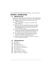
... working environment with sufficient lighting. „ Always disconnect the computer from power outlet before operation. „ Before you for ATX Case X 1 User's Manual X 1 Fully Setup Driver CD X 1 USB 2.0 Cable X1 (optional) S/PDIF out Cable X 1 (optional) 1 Hold the board on the edge, do not try to remove the static charge. „ Avoid touching the components on motherboard or the rear side of the board unless necessary. Loose parts will cause short...
... working environment with sufficient lighting. „ Always disconnect the computer from power outlet before operation. „ Before you for ATX Case X 1 User's Manual X 1 Fully Setup Driver CD X 1 USB 2.0 Cable X1 (optional) S/PDIF out Cable X 1 (optional) 1 Hold the board on the edge, do not try to remove the static charge. „ Avoid touching the components on motherboard or the rear side of the board unless necessary. Loose parts will cause short...
Setup Manual
Page 4
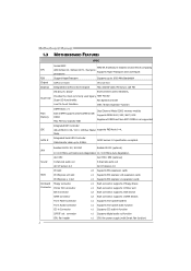
... Mode SATA II Integrated Serial ATA Controller Data transfer rates up to 3 Gb/s. SATA Version 2.0 specification compliant. Motherboard Manual 1.3 MOTHERBOARD FEATURES SPEC Socket AM2 AMD 64 Architecture enables 32 and 64 bit computing CPU AMD Athlon 64 / Athlon 64 FX / Sempron Supports Hyper Transport and Cool=n=Quiet processors FSB Support HyperTransport Supports up to 1000 MHz Bandwidth Chipset GeForce 6100 nForce 410 Graphics Integrated in function S/PDIF out connector x1 Supports digital audio out function CPU Fan header 2 x1 CPU Fan power supply (with Smart Fan...
... Mode SATA II Integrated Serial ATA Controller Data transfer rates up to 3 Gb/s. SATA Version 2.0 specification compliant. Motherboard Manual 1.3 MOTHERBOARD FEATURES SPEC Socket AM2 AMD 64 Architecture enables 32 and 64 bit computing CPU AMD Athlon 64 / Athlon 64 FX / Sempron Supports Hyper Transport and Cool=n=Quiet processors FSB Support HyperTransport Supports up to 1000 MHz Bandwidth Chipset GeForce 6100 nForce 410 Graphics Integrated in function S/PDIF out connector x1 Supports digital audio out function CPU Fan header 2 x1 CPU Fan power supply (with Smart Fan...
Setup Manual
Page 5
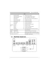
... to monitor. System Fan header Chassis open header (optional) CMOS clear header USB connector Power Connector (24pin) Power Connector (4pin) PS/2 Keyboard PS/2 Mouse Back Panel I/O Serial Port VGA port LAN port USB Port Audio Jack Board Size 244 x 244 (mm) Special Features NVIDIA nTunes RAID 0 / 1 support OS Support Windows 2K / XP TForce 6100 AM2 SPEC x3 System Fan Power supply x1 For chassis intruder detection function x1 Restore CMOS data to factory default x2 Each connector supports 2 front panel USB ports x1 Connects to Power supply x1 Connects to Power supply x1 Connects...
... to monitor. System Fan header Chassis open header (optional) CMOS clear header USB connector Power Connector (24pin) Power Connector (4pin) PS/2 Keyboard PS/2 Mouse Back Panel I/O Serial Port VGA port LAN port USB Port Audio Jack Board Size 244 x 244 (mm) Special Features NVIDIA nTunes RAID 0 / 1 support OS Support Windows 2K / XP TForce 6100 AM2 SPEC x3 System Fan Power supply x1 For chassis intruder detection function x1 Restore CMOS data to factory default x2 Each connector supports 2 front panel USB ports x1 Connects to Power supply x1 Connects to Power supply x1 Connects...
Setup Manual
Page 11
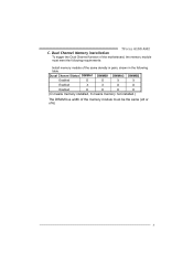
Dual Channel Memory installation To trigger the Dual Channel function of the same density in pairs, shown in the following table. Duual Channel Status DIMMA1 DIMMB1 DIMMA2 DIMMB2 Enabled O O X X Enabled X X O O Enabled O O O O (O means memory installed, X means memory not installed.) The DRAM bus width of the memory module must meet the following requirements: Install memory module of the motherboard, the memory module must be the same (x8 or x16) 9 TForce 6100 AM2 C.
Dual Channel Memory installation To trigger the Dual Channel function of the same density in pairs, shown in the following table. Duual Channel Status DIMMA1 DIMMB1 DIMMA2 DIMMB2 Enabled O O X X Enabled X X O O Enabled O O O O (O means memory installed, X means memory not installed.) The DRAM bus width of the memory module must meet the following requirements: Install memory module of the motherboard, the memory module must be the same (x8 or x16) 9 TForce 6100 AM2 C.
Setup Manual
Page 12
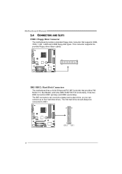
... two HDD connectors IDE1 (primary) and IDE2 (secondary). This connector supports the provided floppy drive ribbon cables. 33 1 34 2 IDE1/IDE2: Hard Disk Connectors The motherboard has a 32-bit Enhanced PCI IDE Controller that supports 360K, 720K, 1.2M, 1.44M and 2.88M floppy disk types. The IDE connectors can connect a master and a slave drive, so you can connect up to IDE1. 40 39 2 1 IDE2 IDE1 10 Motherboard Manual 2.4 CONNECTORS AND SLOTS FDD1: Floppy Disk Connector The motherboard provides a standard floppy disk connector that provides PIO Mode 0~4, Bus Master...
... two HDD connectors IDE1 (primary) and IDE2 (secondary). This connector supports the provided floppy drive ribbon cables. 33 1 34 2 IDE1/IDE2: Hard Disk Connectors The motherboard has a 32-bit Enhanced PCI IDE Controller that supports 360K, 720K, 1.2M, 1.44M and 2.88M floppy disk types. The IDE connectors can connect a master and a slave drive, so you can connect up to IDE1. 40 39 2 1 IDE2 IDE1 10 Motherboard Manual 2.4 CONNECTORS AND SLOTS FDD1: Floppy Disk Connector The motherboard provides a standard floppy disk connector that provides PIO Mode 0~4, Bus Master...
Setup Manual
Page 14
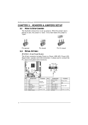
...Hard drive 10 LED 12 Reset button 14 16 Assignment Sleep control Ground N/A Power LED (+) Power LED (+) Power LED (-) Power button Ground Function Sleep button N/A Power LED Power-on pins, the jumper is "close", if not, that means the jumper is placed on button 12 When the jumper cap is "open". It allows user to set up jumpers. Pin opened Pin closed Pin1-2 closed 3.2 DETAIL SETTINGS JPANEL1: Front Panel Header This 20-pin connector includes Power-on, Reset, HDD LED, Power LED, Sleep button, speaker and IrDA Connection. Motherboard Manual CHAPTER 3: HEADERS & JUMPERS SETUP...
...Hard drive 10 LED 12 Reset button 14 16 Assignment Sleep control Ground N/A Power LED (+) Power LED (+) Power LED (-) Power button Ground Function Sleep button N/A Power LED Power-on pins, the jumper is "close", if not, that means the jumper is placed on button 12 When the jumper cap is "open". It allows user to set up jumpers. Pin opened Pin closed Pin1-2 closed 3.2 DETAIL SETTINGS JPANEL1: Front Panel Header This 20-pin connector includes Power-on, Reset, HDD LED, Power LED, Sleep button, speaker and IrDA Connection. Motherboard Manual CHAPTER 3: HEADERS & JUMPERS SETUP...
Setup Manual
Page 19
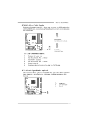
... the motherboard. 1 3 Pin 1-2 Close: Normal Operation (default). 1 1 3 Pin 2-3 Close: Clear CMOS data. ※ Clear CMOS Procedures: 1. TForce 6100 AM2 JCMOS1: Clear CMOS Header By placing the jumper on pin2-3, it will record to the CMOS and show the message on the AC. 6. Set the jumper to "Pin 1-2 close ". 3. Remove AC power line. 2. Reset your desired password or clear the CMOS data. Wait for five seconds. 4. Power on next boot-up. Pin Assignment 1 Case open status. JCI1: Chassis Open Header (optional) This connector allows...
... the motherboard. 1 3 Pin 1-2 Close: Normal Operation (default). 1 1 3 Pin 2-3 Close: Clear CMOS data. ※ Clear CMOS Procedures: 1. TForce 6100 AM2 JCMOS1: Clear CMOS Header By placing the jumper on pin2-3, it will record to the CMOS and show the message on the AC. 6. Set the jumper to "Pin 1-2 close ". 3. Remove AC power line. 2. Reset your desired password or clear the CMOS data. Wait for five seconds. 4. Power on next boot-up. Pin Assignment 1 Case open status. JCI1: Chassis Open Header (optional) This connector allows...
Setup Manual
Page 24
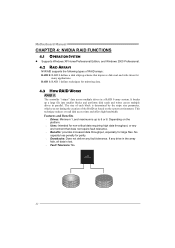
Motherboard Manual CHAPTER 4: NVIDIA RAID FUNCTIONS 4.1 OPERATION SYSTEM z Supports Windows XP Home/Professional Edition, and Windows 2000 Professional. 4.2 RAID ARRAYS NVRAID supports the following types of the RAID set during the creation of RAID arrays: RAID 0: RAID 0 defines a disk striping scheme that does not require fault tolerance. Benefits: provides increased data throughput, especially for large files. It breaks up to 6 or 8. Features and Benefits Drives: Minimum...
Motherboard Manual CHAPTER 4: NVIDIA RAID FUNCTIONS 4.1 OPERATION SYSTEM z Supports Windows XP Home/Professional Edition, and Windows 2000 Professional. 4.2 RAID ARRAYS NVRAID supports the following types of the RAID set during the creation of RAID arrays: RAID 0: RAID 0 defines a disk striping scheme that does not require fault tolerance. Benefits: provides increased data throughput, especially for large files. It breaks up to 6 or 8. Features and Benefits Drives: Minimum...
Setup Manual
Page 31
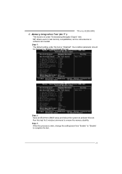
TForce 6100 AM2 C. Step 3: When the process is "Disabled"; MIT allows users to complete the test. 29 Step 1: The default setting under "Overclocking Navigator Engine" item. Run this test. Memory Integration Test (M.I.T.): This function is under this item is done, change the setting back from CMOS setup and reboot the system to activate this test for 5 minutes (minimum) to ensure the memory stability. the condition...
TForce 6100 AM2 C. Step 3: When the process is "Disabled"; MIT allows users to complete the test. 29 Step 1: The default setting under "Overclocking Navigator Engine" item. Run this test. Memory Integration Test (M.I.T.): This function is under this item is done, change the setting back from CMOS setup and reboot the system to activate this test for 5 minutes (minimum) to ensure the memory stability. the condition...
Setup Manual
Page 45
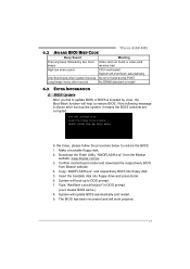
... two short Video card not found or video card beeps memory bad High-low siren sound CPU overheated System will boot-up No error found during POST Long beeps every other second No DRAM detected or install 6.3 EXTRA INFORMATION A. System will shut down automatically One Short beep when system boot-up to restore the BIOS: 1. System will work properly. 43 Copy "AWDFLASH.exe" and respectively BIOS into floppy drive and press Enter. 6. Make a bootable floppy disk. 2. In this Case...
... two short Video card not found or video card beeps memory bad High-low siren sound CPU overheated System will boot-up No error found during POST Long beeps every other second No DRAM detected or install 6.3 EXTRA INFORMATION A. System will shut down automatically One Short beep when system boot-up to restore the BIOS: 1. System will work properly. 43 Copy "AWDFLASH.exe" and respectively BIOS into floppy drive and press Enter. 6. Make a bootable floppy disk. 2. In this Case...
Setup Manual
Page 67
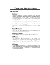
... of Advanced Configuration and Power interface specification (ACPI). The rest of this motherboard. It provides ASL code for power management and device configuration capabilities as keyboard, mouse, serial ports and disk drives. Power management features are supported. The Setup program allows users to modify the basic system configuration and save these settings to CMOS RAM. Sleep and Suspend power management modes are implemented via the System Management Interrupt (SMI). TForce 6100 AM2 BIOS Setup BIOS Setup Introduction The purpose of this manual is...
... of Advanced Configuration and Power interface specification (ACPI). The rest of this motherboard. It provides ASL code for power management and device configuration capabilities as keyboard, mouse, serial ports and disk drives. Power management features are supported. The Setup program allows users to modify the basic system configuration and save these settings to CMOS RAM. Sleep and Suspend power management modes are implemented via the System Management Interrupt (SMI). TForce 6100 AM2 BIOS Setup BIOS Setup Introduction The purpose of this manual is...
Setup Manual
Page 77
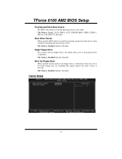
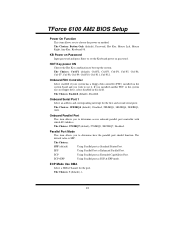
TForce 6100 AM2 BIOS Setup First/Second/Third Boot Device The BIOS will attempt to swap logical drive assignments. The Choices: Enabled (default), Disabled Swap Floppy Drive For systems with two floppy drives, this option allows you to load the operating system in this option reduces the time it failed to determine if they have 40 or 80 tracks during boot up . The Choices: Floppy, LS120, HDD-0, SCSI, CDROM, HDD-1, HDD-2, HDD-3, ZIP100, LAN, HPT370, Disabled. The Choices...
TForce 6100 AM2 BIOS Setup First/Second/Third Boot Device The BIOS will attempt to swap logical drive assignments. The Choices: Enabled (default), Disabled Swap Floppy Drive For systems with two floppy drives, this option allows you to load the operating system in this option reduces the time it failed to determine if they have 40 or 80 tracks during boot up . The Choices: Floppy, LS120, HDD-0, SCSI, CDROM, HDD-1, HDD-2, HDD-3, ZIP100, LAN, HPT370, Disabled. The Choices...
Setup Manual
Page 80
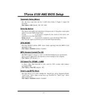
... system boots up. TForce 6100 AM2 BIOS Setup Typematic Delay (Msec) Sets the delay time after the key is required to access the Setup Utility only. This will enable only individuals with memory exceeding 64MB. OS Select For DRAM > 64MB A choice other than Non-OS2 is also required to use the CMOS Setup Utility. MPS Version Control For OS The BIOS supports version 1.1 and 1.4 of the Intel multiprocessor specification. The Choices: Non-OS2 (default), OS2. Disabled...
... system boots up. TForce 6100 AM2 BIOS Setup Typematic Delay (Msec) Sets the delay time after the key is required to access the Setup Utility only. This will enable only individuals with memory exceeding 64MB. OS Select For DRAM > 64MB A choice other than Non-OS2 is also required to use the CMOS Setup Utility. MPS Version Control For OS The BIOS supports version 1.1 and 1.4 of the Intel multiprocessor specification. The Choices: Non-OS2 (default), OS2. Disabled...
Setup Manual
Page 82
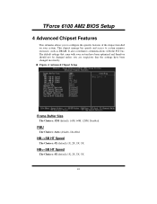
... TForce 6100 AM2 BIOS Setup 4 Advanced Chipset Features This submenu allows you are suspicious that came with the PCI bus. The default settings that the settings have been changed incorrectly. This chipset manage bus speeds and access to configure the specific features of the chipset installed on your system have been optimized and therefore should not be changed unless you to system memory resources, such as DRAM. Advanced Chipset Setup Frame Buffer Size The Choices: 32M (default...
... TForce 6100 AM2 BIOS Setup 4 Advanced Chipset Features This submenu allows you are suspicious that came with the PCI bus. The default settings that the settings have been changed incorrectly. This chipset manage bus speeds and access to configure the specific features of the chipset installed on your system have been optimized and therefore should not be changed unless you to system memory resources, such as DRAM. Advanced Chipset Setup Frame Buffer Size The Choices: 32M (default...
Setup Manual
Page 86
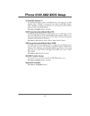
...: Enabled (default), Disabled. As well, your system software both support Ultra DMA, select Auto to install a primary and/or secondary add-in your system. TForce 6100 AM2 BIOS Setup On-chip IDE Channel 0/1 The motherboard chipset contains a PCI IDE interface with support for each device. Select "Disabled" to activate the first and/or second IDE interface. IDE Primary/Secondary/Master/Slave UDMA Ultra DMA function can be implemented if it is supported by the IDE hard drives in IDE...
...: Enabled (default), Disabled. As well, your system software both support Ultra DMA, select Auto to install a primary and/or secondary add-in your system. TForce 6100 AM2 BIOS Setup On-chip IDE Channel 0/1 The motherboard chipset contains a PCI IDE interface with support for each device. Select "Disabled" to activate the first and/or second IDE interface. IDE Primary/Secondary/Master/Slave UDMA Ultra DMA function can be implemented if it is supported by the IDE hard drives in IDE...
Setup Manual
Page 88
...: 3 (default), 1. 22 ECP Using Parallel port as Standard Printer Port. ECP Mode Use DMA Select a DMA Channel for the first and second serial ports. The Choices: Button Only (default), Password, Hot Key, Mouse Left, Mouse Right, Any Key, Keyboard 98. Onboard FDC Controller Select enabled if your system has a floppy disk controller (FDC) installed on the system board and you installed another FDC or the system uses no floppy drive, select disabled in this field. The Choices: Enabled (default), Disabled. KB Power...
...: 3 (default), 1. 22 ECP Using Parallel port as Standard Printer Port. ECP Mode Use DMA Select a DMA Channel for the first and second serial ports. The Choices: Button Only (default), Password, Hot Key, Mouse Left, Mouse Right, Any Key, Keyboard 98. Onboard FDC Controller Select enabled if your system has a floppy disk controller (FDC) installed on the system board and you installed another FDC or the system uses no floppy drive, select disabled in this field. The Choices: Enabled (default), Disabled. KB Power...
Setup Manual
Page 93
... enable or disable Wake On LAN from Soft-Off function. USB Resume from S3/S4 This item allows you to wake up from S3 with USB device. The Choices: Disabled (default), Enabled. Note: If you have change the setting, you to cut off the power immediately, and Delay 4 Sec. TForce 6100 AM2 BIOS Setup Soft-Off by Alarm This function is for setting date and time for 4 seconds to enable or disable Wake...
... enable or disable Wake On LAN from Soft-Off function. USB Resume from S3/S4 This item allows you to wake up from S3 with USB device. The Choices: Disabled (default), Enabled. Note: If you have change the setting, you to cut off the power immediately, and Delay 4 Sec. TForce 6100 AM2 BIOS Setup Soft-Off by Alarm This function is for setting date and time for 4 seconds to enable or disable Wake...
Setup Manual
Page 95
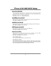
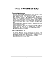
TForce 6100 AM2 BIOS Setup Reset Configuration Data The system BIOS supports the PnP feature which requires the system to record which resources are reserved in the system BIOS. The system needs to record and update ESCD to the PCI Bus or provides for each peripheral. These locations are assigned and protects resources from the last one. Resources Controlled By By Choosing "Auto(ESCD)" (default), the system BIOS will...
TForce 6100 AM2 BIOS Setup Reset Configuration Data The system BIOS supports the PnP feature which requires the system to record which resources are reserved in the system BIOS. The system needs to record and update ESCD to the PCI Bus or provides for each peripheral. These locations are assigned and protects resources from the last one. Resources Controlled By By Choosing "Auto(ESCD)" (default), the system BIOS will...

Setup Manual
Page 102
... The Choices: Disable (Default), Enable. Memory Hole Remapping The Choices: Enable (Default), Disable. Trfc0 for DIMM1 The Choices: 75ns (Default), 105ns, 127.5ns, 195ns, 327.5ns. Trfc0 for DIMM0 The Choices: 75ns (Default), 105ns, 127.5ns, 195ns, 327.5ns. Twtr Command Delay The Choices: 3 bus Clocks (Default), 1 bus Clock, 2 bus clocks. TForce 6100 AM2 BIOS Setup DQS Training Control The Choices: Perform DQS (Default), Skip DQS CKE base power down The Choices: per Channel (Default)., Per...
... The Choices: Disable (Default), Enable. Memory Hole Remapping The Choices: Enable (Default), Disable. Trfc0 for DIMM1 The Choices: 75ns (Default), 105ns, 127.5ns, 195ns, 327.5ns. Trfc0 for DIMM0 The Choices: 75ns (Default), 105ns, 127.5ns, 195ns, 327.5ns. Twtr Command Delay The Choices: 3 bus Clocks (Default), 1 bus Clock, 2 bus clocks. TForce 6100 AM2 BIOS Setup DQS Training Control The Choices: Perform DQS (Default), Skip DQS CKE base power down The Choices: per Channel (Default)., Per...


