
Setup Manual
Page 1
TForce 6100 AM2 Setup Manual FCC Information and Copyright This equipment has been tested and found in this user's manual. Further the vendor reserves the right to revise this publication and to make changes to the contents here without obligation to notify ... no guarantee that interference will not be changed without first obtaining the vendor's approval in a residential installation. The content of this user's manual is subject to provide reasonable protection against harmful interference in writing. There is not allowed without notice and we will not occur in accordance with...
TForce 6100 AM2 Setup Manual FCC Information and Copyright This equipment has been tested and found in this user's manual. Further the vendor reserves the right to revise this publication and to make changes to the contents here without obligation to notify ... no guarantee that interference will not be changed without first obtaining the vendor's approval in a residential installation. The content of this user's manual is subject to provide reasonable protection against harmful interference in writing. There is not allowed without notice and we will not occur in accordance with...
Setup Manual
Page 3
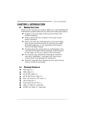
... stable working environment with sufficient lighting. „ Always disconnect the computer from power outlet before operation. „ Before you for ATX Case X 1 User's Manual X 1 Fully Setup Driver CD X 1 USB 2.0 Cable X1 (optional) S/PDIF out Cable X 1 (optional) 1 Hold the board on the edge,... the static charge. „ Avoid touching the components on motherboard or the rear side of the board unless necessary. CHAPTER 1: INTRODUCTION TForce 6100 AM2 1.1 BEFORE YOU START Thank you take the motherboard out from dangerous area, such as heat source, humid air and water. 1.2 PACKAGE...
... stable working environment with sufficient lighting. „ Always disconnect the computer from power outlet before operation. „ Before you for ATX Case X 1 User's Manual X 1 Fully Setup Driver CD X 1 USB 2.0 Cable X1 (optional) S/PDIF out Cable X 1 (optional) 1 Hold the board on the edge,... the static charge. „ Avoid touching the components on motherboard or the rear side of the board unless necessary. CHAPTER 1: INTRODUCTION TForce 6100 AM2 1.1 BEFORE YOU START Thank you take the motherboard out from dangerous area, such as heat source, humid air and water. 1.2 PACKAGE...
Setup Manual
Page 4
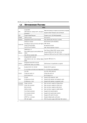
...x1 Supports front panel facilities Front Audio Connector x1 Supports front panel audio function CD-in Connector x1 Supports CD audio-in GeForce 6100 Chipset Max Shared Video Memory is not supported Integrated IDE Controller IDE Ultra DMA 33 / 66 / 100 / 133 Bus ... Super I/O ITE 8712F / 8716F Environment Control initiatives, Provides the most commonly used legacy H/W Monitor Super I/O functionality. Motherboard Manual 1.3 MOTHERBOARD FEATURES SPEC Socket AM2 AMD 64 Architecture enables 32 and 64 bit computing CPU AMD Athlon 64 / Athlon 64 FX / Sempron Supports Hyper Transport...
...x1 Supports front panel facilities Front Audio Connector x1 Supports front panel audio function CD-in Connector x1 Supports CD audio-in GeForce 6100 Chipset Max Shared Video Memory is not supported Integrated IDE Controller IDE Ultra DMA 33 / 66 / 100 / 133 Bus ... Super I/O ITE 8712F / 8716F Environment Control initiatives, Provides the most commonly used legacy H/W Monitor Super I/O functionality. Motherboard Manual 1.3 MOTHERBOARD FEATURES SPEC Socket AM2 AMD 64 Architecture enables 32 and 64 bit computing CPU AMD Athlon 64 / Athlon 64 FX / Sempron Supports Hyper Transport...
Setup Manual
Page 6
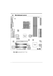
Motherboard Manual 1.5 MOTHERBOARD LAYOUT JKBMS1 JKBV1 JD DRII_ 22V JCOM1 DIMMB2 DIMMA2 DIMMB1 DIMMA1 Socket A M2 JVGA1 JPRN T1 J ATXPWR1 JUSB1 J USBV1 JUSBLAN1 J ATXPWR2 IDE1 IDE2 JAUDIO1 JFAUDIO1 Codec Super I/O JCFAN1 LAN GeForce 6100 BAT1 PCI-EX1_1 J CDIN1 PCI-EX16 PCI1 JSPDIF_OUT1 PCI2 FDD1 JSFAN2 LED_D1 LED_D2 JNFAN1 J USBV2 JUSB2 JUSB3 BIOS JSFAN1 PWRSW1 RSTSW2 nForce 410 JSATA2 JSATA1 (Optional)JCI1 JCMOS1 J PANEL1 IR (optional) Note: ■ represents the 1st pin. 4
Motherboard Manual 1.5 MOTHERBOARD LAYOUT JKBMS1 JKBV1 JD DRII_ 22V JCOM1 DIMMB2 DIMMA2 DIMMB1 DIMMA1 Socket A M2 JVGA1 JPRN T1 J ATXPWR1 JUSB1 J USBV1 JUSBLAN1 J ATXPWR2 IDE1 IDE2 JAUDIO1 JFAUDIO1 Codec Super I/O JCFAN1 LAN GeForce 6100 BAT1 PCI-EX1_1 J CDIN1 PCI-EX16 PCI1 JSPDIF_OUT1 PCI2 FDD1 JSFAN2 LED_D1 LED_D2 JNFAN1 J USBV2 JUSB2 JUSB3 BIOS JSFAN1 PWRSW1 RSTSW2 nForce 410 JSATA2 JSATA1 (Optional)JCI1 JCMOS1 J PANEL1 IR (optional) Note: ■ represents the 1st pin. 4
Setup Manual
Page 8
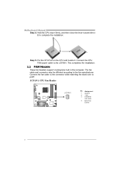
... CPU Fan on the CPU and buckle it. Connect the fan cable to the connector while matching the black wire to complete the installation. Motherboard Manual Step 4: Hold the CPU down firmly, and then close the lever toward direct B to pin#1.
... CPU Fan on the CPU and buckle it. Connect the fan cable to the connector while matching the black wire to complete the installation. Motherboard Manual Step 4: Hold the CPU down firmly, and then close the lever toward direct B to pin#1.
Setup Manual
Page 10
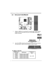
B. Unlock a DIMM slot by pressing the retaining clips outward. Insert the DIMM vertically and firmly into the slot until the retaining chip snap back in place and the DIMM is 4GB. 8 Align a DIMM on the slot such that the notch on the DIMM matches the break on the Slot. 2. Motherboard Manual 2.3 INSTALLING SYSTEM MEMORY 1. Memory Capacity DIMM Socket Location DDR Module DIMMA1 256MB/512MB/1024MB DIMMB1 256MB/512MB/1024MB DIMMA2 256MB/512MB/1024MB DIMMB2 256MB/512MB/1024MB Total Memory Size Max is properly seated.
B. Unlock a DIMM slot by pressing the retaining clips outward. Insert the DIMM vertically and firmly into the slot until the retaining chip snap back in place and the DIMM is 4GB. 8 Align a DIMM on the slot such that the notch on the DIMM matches the break on the Slot. 2. Motherboard Manual 2.3 INSTALLING SYSTEM MEMORY 1. Memory Capacity DIMM Socket Location DDR Module DIMMA1 256MB/512MB/1024MB DIMMB1 256MB/512MB/1024MB DIMMA2 256MB/512MB/1024MB DIMMB2 256MB/512MB/1024MB Total Memory Size Max is properly seated.
Setup Manual
Page 12
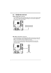
.../IDE2: Hard Disk Connectors The motherboard has a 32-bit Enhanced PCI IDE Controller that supports 360K, 720K, 1.2M, 1.44M and 2.88M floppy disk types. Motherboard Manual 2.4 CONNECTORS AND SLOTS FDD1: Floppy Disk Connector The motherboard provides a standard floppy disk connector that provides PIO Mode 0~4, Bus Master, and Ultra DMA 33/66...
.../IDE2: Hard Disk Connectors The motherboard has a 32-bit Enhanced PCI IDE Controller that supports 360K, 720K, 1.2M, 1.44M and 2.88M floppy disk types. Motherboard Manual 2.4 CONNECTORS AND SLOTS FDD1: Floppy Disk Connector The motherboard provides a standard floppy disk connector that provides PIO Mode 0~4, Bus Master, and Ultra DMA 33/66...
Setup Manual
Page 14
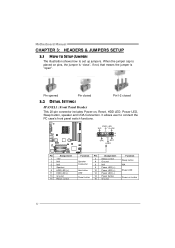
... LED (-) Power button Ground Function Sleep button N/A Power LED Power-on pins, the jumper is "close", if not, that means the jumper is "open". Motherboard Manual CHAPTER 3: HEADERS & JUMPERS SETUP 3.1 HOW TO SETUP JUMPERS The illustration shows how to connect the PC case's front panel switch functions. When the jumper cap...
... LED (-) Power button Ground Function Sleep button N/A Power LED Power-on pins, the jumper is "close", if not, that means the jumper is "open". Motherboard Manual CHAPTER 3: HEADERS & JUMPERS SETUP 3.1 HOW TO SETUP JUMPERS The illustration shows how to connect the PC case's front panel switch functions. When the jumper cap...
Setup Manual
Page 16
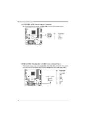
Motherboard Manual JATXPWR2: ATX Power Source Connector By connecting this connector, it will provide +12V to CPU power circuit. 3 2 Pin 1 Assignment +12V 4 1 2 +12V 3 Ground 4 Ground JUSB2/JUSB3: Headers for USB 2.0 Ports at Front Panel This header allows user to connect additional USB cable on the PC front panel, and also can be connected with internal USB devices, like USB card reader. JUSB2 JUSB3 4 USB- 2 10 5 USB+ 6 USB+ 7 Ground 1 9 8 Ground 9 Key 10 NC 14 Pin Assignment 1 +5V (fused) 2 +5V (fused) 3 USB-
Motherboard Manual JATXPWR2: ATX Power Source Connector By connecting this connector, it will provide +12V to CPU power circuit. 3 2 Pin 1 Assignment +12V 4 1 2 +12V 3 Ground 4 Ground JUSB2/JUSB3: Headers for USB 2.0 Ports at Front Panel This header allows user to connect additional USB cable on the PC front panel, and also can be connected with internal USB devices, like USB card reader. JUSB2 JUSB3 4 USB- 2 10 5 USB+ 6 USB+ 7 Ground 1 9 8 Ground 9 Key 10 NC 14 Pin Assignment 1 +5V (fused) 2 +5V (fused) 3 USB-
Setup Manual
Page 18
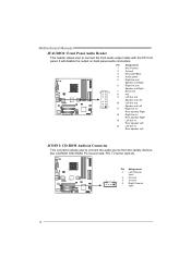
... allows user to connect the front audio output cable with the PC front panel. It will disable the output on back panel audio connectors. Motherboard Manual JFAUDIO1: Front Panel Audio Header This header allows user to connect the audio source from the variaty devices, like CD-ROM, DVD-ROM, PCI sound...
... allows user to connect the front audio output cable with the PC front panel. It will disable the output on back panel audio connectors. Motherboard Manual JFAUDIO1: Front Panel Audio Header This header allows user to connect the audio source from the variaty devices, like CD-ROM, DVD-ROM, PCI sound...
Setup Manual
Page 20
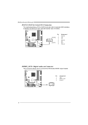
Pin 1 J SATA2 2 14 7 3 4 5 J SATA1 6 7 Assignment Ground TX+ TXGround RXRX+ Ground JSPDIF_OUT1: Digital Audio-out Connector This connector allows user to SATA Controller with 2 channels SATA interface, it satisfies the SATA 2.0 spec and with transfer rate of 3.0Gb/s. Motherboard Manual JSATA1~JSATA2: Serial ATA Connectors The motherboard has a PCI to connect the PCI bracket SPDIF output header. Pin Assignment 1 +5V 2 SPDIF_OUT 3 Ground 3 1 18
Pin 1 J SATA2 2 14 7 3 4 5 J SATA1 6 7 Assignment Ground TX+ TXGround RXRX+ Ground JSPDIF_OUT1: Digital Audio-out Connector This connector allows user to SATA Controller with 2 channels SATA interface, it satisfies the SATA 2.0 spec and with transfer rate of 3.0Gb/s. Motherboard Manual JSATA1~JSATA2: Serial ATA Connectors The motherboard has a PCI to connect the PCI bracket SPDIF output header. Pin Assignment 1 +5V 2 SPDIF_OUT 3 Ground 3 1 18
Setup Manual
Page 21
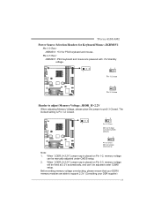
When "JDDR_II>2.2V" jumper cap is placed on Pin 1-2, memory voltage can 't be manually adjusted under COMS setup. Before setting memory voltage overclocking, please ensure that your DDR supplier) 19 When "JDDR_II>2.2V" jumper cap is ... 2. The Default setting is Pin 1-2 Closed. 13 1 Pin 1-2 Close: Memory Voltage controlled by BIOS (default). 13 Pin 2-3 Close: Memory voltage Overclocking Note: 1. TForce 6100 AM2 Power Source Selection Headers for Keyboard/Mouse: JKBMSV1 Pin 1-2 Close: JKBMSV1: +5V for PS/2 keyboard and mouse。 Pin 2-3 Close: JKBMSV1: PS/2 keyboard and mouse...
When "JDDR_II>2.2V" jumper cap is placed on Pin 1-2, memory voltage can 't be manually adjusted under COMS setup. Before setting memory voltage overclocking, please ensure that your DDR supplier) 19 When "JDDR_II>2.2V" jumper cap is ... 2. The Default setting is Pin 1-2 Closed. 13 1 Pin 1-2 Close: Memory Voltage controlled by BIOS (default). 13 Pin 2-3 Close: Memory voltage Overclocking Note: 1. TForce 6100 AM2 Power Source Selection Headers for Keyboard/Mouse: JKBMSV1 Pin 1-2 Close: JKBMSV1: +5V for PS/2 keyboard and mouse。 Pin 2-3 Close: JKBMSV1: PS/2 keyboard and mouse...
Setup Manual
Page 22
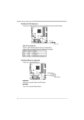
PWRSW1 PWRSW1: This is an on-board Reset button. RSTSW2 20 On-Board Buttons (optional) There are 2 LED indicators on the motherboard to the table below for different messages: LED_D1 ON ON OFF OFF LED_D2 ON OFF ON OFF Message Norm al Mem ory Error VGA Error Abnormal: CPU / Chipset error. LED_D1 LED_D2 LED_D1 and LED_D2: These 2 LED indicate system power on -board Power On/Off button. Please refer to show system status. RSTSW2: This is an on diagnostics. Motherboard Manual On-Board LED Indicators There are 2 on-board buttons.
PWRSW1 PWRSW1: This is an on-board Reset button. RSTSW2 20 On-Board Buttons (optional) There are 2 LED indicators on the motherboard to the table below for different messages: LED_D1 ON ON OFF OFF LED_D2 ON OFF ON OFF Message Norm al Mem ory Error VGA Error Abnormal: CPU / Chipset error. LED_D1 LED_D2 LED_D1 and LED_D2: These 2 LED indicate system power on -board Power On/Off button. Please refer to show system status. RSTSW2: This is an on diagnostics. Motherboard Manual On-Board LED Indicators There are 2 on-board buttons.
Setup Manual
Page 24
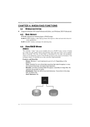
... and write times for mirroring data. 4.3 HOW RAID WORKS RAID 0: The controller "stripes" data across multiple drives in parallel. It breaks up to 6 or 8. Motherboard Manual CHAPTER 4: NVIDIA RAID FUNCTIONS 4.1 OPERATION SYSTEM z Supports Windows XP Home/Professional Edition, and Windows 2000 Professional. 4.2 RAID ARRAYS NVRAID supports the following types of RAID...
... and write times for mirroring data. 4.3 HOW RAID WORKS RAID 0: The controller "stripes" data across multiple drives in parallel. It breaks up to 6 or 8. Motherboard Manual CHAPTER 4: NVIDIA RAID FUNCTIONS 4.1 OPERATION SYSTEM z Supports Windows XP Home/Professional Edition, and Windows 2000 Professional. 4.2 RAID ARRAYS NVRAID supports the following types of RAID...

Setup Manual
Page 25
...becomes unavailable because of data if the active volume or drive is ideal for small databases or any other application that eliminates tedious manual backups to more detailed setup information, please refer to the Driver CD, or go to http://www.nvidia.com/page/pg_20011106217193.html...For more expensive and less reliable media. RAID techniques can reside on the same disk or on a second redundant drive in a RAID 1 array system. TForce 6100 AM2 RAID 1: Every read and write is actually carried out in parallel across 2 disk drives in the array. RAID 1 provides a hot-standby copy of a...
...becomes unavailable because of data if the active volume or drive is ideal for small databases or any other application that eliminates tedious manual backups to more detailed setup information, please refer to the Driver CD, or go to http://www.nvidia.com/page/pg_20011106217193.html...For more expensive and less reliable media. RAID techniques can reside on the same disk or on a second redundant drive in a RAID 1 array system. TForce 6100 AM2 RAID 1: Every read and write is actually carried out in parallel across 2 disk drives in the array. RAID 1 provides a hot-standby copy of a...
Setup Manual
Page 26
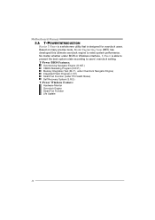
... Function (under BIOS or Windows interface, T-Power is designed for overclock users. Based on many precise tests, Biostar Engineering Team (BET) has developed this ultimate overclock engine to users' overclock setting. Motherboard Manual 5.1: T-POWER INTRODUCTION Biostar T-Power is a whole new utility that is able to present the best system state according to raise...
... Function (under BIOS or Windows interface, T-Power is designed for overclock users. Based on many precise tests, Biostar Engineering Team (BET) has developed this ultimate overclock engine to users' overclock setting. Motherboard Manual 5.1: T-POWER INTRODUCTION Biostar T-Power is a whole new utility that is able to present the best system state according to raise...
Setup Manual
Page 27
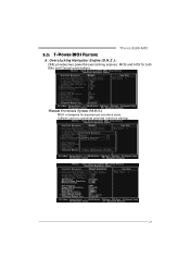
TForce 6100 AM2 5.2: T-POWER BIOS FEATURE A. Manual Overclock System (M.O.S.) MOS is designed for both Elite and Casual overclockers. It allows users to customize personal overclock settings. 25 Overclocking Navigator Engine (O.N.E.): ONE provides two powerful overclocking engines: MOS and AOS for experienced overclock users.
TForce 6100 AM2 5.2: T-POWER BIOS FEATURE A. Manual Overclock System (M.O.S.) MOS is designed for both Elite and Casual overclockers. It allows users to customize personal overclock settings. 25 Overclocking Navigator Engine (O.N.E.): ONE provides two powerful overclocking engines: MOS and AOS for experienced overclock users.
Setup Manual
Page 28
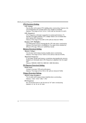
... increase VGA card performance. Memclock Frequency: To get better system performance, sometimes downgrading the memory frequency is necessary when CPU frequency is x4 (800MHz). Motherboard Manual CPU Overclock Setting: CPU Voltage: This function will increase chipset stability when overclocking.
... increase VGA card performance. Memclock Frequency: To get better system performance, sometimes downgrading the memory frequency is necessary when CPU frequency is x4 (800MHz). Motherboard Manual CPU Overclock Setting: CPU Voltage: This function will increase chipset stability when overclocking.
Setup Manual
Page 30
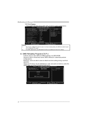
... experiments, the Atholon64 FX CPU is not suitable for customizing system configurations. feature. the difference will raise about 25%~30% of whole system performance. Motherboard Manual V12 Tech Engine: This setting will be based on the selected CPU model. 2. CMOS Reloading Program (C.R.P.): It allows users to save different CMOS settings into...
... experiments, the Atholon64 FX CPU is not suitable for customizing system configurations. feature. the difference will raise about 25%~30% of whole system performance. Motherboard Manual V12 Tech Engine: This setting will be based on the selected CPU model. 2. CMOS Reloading Program (C.R.P.): It allows users to save different CMOS settings into...
Setup Manual
Page 32
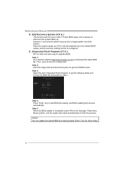
Self Recovery System (S.R.S.): This function can't be re-configured. Step 1: Go to Biostar website (http://www.biostar.com.tw) to get the following frame and choose the BIOS file downloaded in the default BIOS setting, and all overclock settings will process automatically. ... , S.R.S. Advise: You can prevent system hang-up due to finish the process. Step 4: Press "Enter" key to upgrade BIOS. When the system hangs up . Motherboard Manual D.
Self Recovery System (S.R.S.): This function can't be re-configured. Step 1: Go to Biostar website (http://www.biostar.com.tw) to get the following frame and choose the BIOS file downloaded in the default BIOS setting, and all overclock settings will process automatically. ... , S.R.S. Advise: You can prevent system hang-up due to finish the process. Step 4: Press "Enter" key to upgrade BIOS. When the system hangs up . Motherboard Manual D.

