
Setup Manual
Page 2
Table of Contents Chapter 1: Introduction 1 1.1 Before You Start 1 1.2 Package Checklist 1 1.3 Motherboard Features 2 1.4 Rear Panel Connectors 3 1.5 Motherboard Layout 4 Chapter 2: Hardware Installation 5 2.1 Installing Central Processing Unit (CPU 5 2.2 FAN Headers 6 2.3 Installing System Memory 8 2.4 Connectors and Slots 10 Chapter 3: Headers & Jumpers Setup 12 3.1 How to ...
Table of Contents Chapter 1: Introduction 1 1.1 Before You Start 1 1.2 Package Checklist 1 1.3 Motherboard Features 2 1.4 Rear Panel Connectors 3 1.5 Motherboard Layout 4 Chapter 2: Hardware Installation 5 2.1 Installing Central Processing Unit (CPU 5 2.2 FAN Headers 6 2.3 Installing System Memory 8 2.4 Connectors and Slots 10 Chapter 3: Headers & Jumpers Setup 12 3.1 How to ...
Setup Manual
Page 3
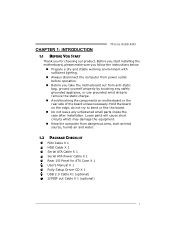
... the board. „ Do not leave any unfastened small parts inside the case after installation. CHAPTER 1: INTRODUCTION TForce 6100 AM2 1.1 BEFORE YOU START Thank you take the motherboard out from dangerous area, such as heat source, humid air and water. 1.2 PACKAGE CHECKLIST FDD Cable X 1...Cable X 1 Serial ATA Cable X 1 Serial ATA Power Cable X 1 Rear I/O Panel for choosing our product. Before you start installing the motherboard, please make sure you follow the instructions below: „ Prepare a dry and stable working environment with sufficient lighting. „ Always disconnect the ...
... the board. „ Do not leave any unfastened small parts inside the case after installation. CHAPTER 1: INTRODUCTION TForce 6100 AM2 1.1 BEFORE YOU START Thank you take the motherboard out from dangerous area, such as heat source, humid air and water. 1.2 PACKAGE CHECKLIST FDD Cable X 1...Cable X 1 Serial ATA Cable X 1 Serial ATA Power Cable X 1 Rear I/O Panel for choosing our product. Before you start installing the motherboard, please make sure you follow the instructions below: „ Prepare a dry and stable working environment with sufficient lighting. „ Always disconnect the ...
Setup Manual
Page 4
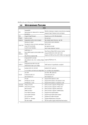
Motherboard Manual 1.3 MOTHERBOARD FEATURES SPEC Socket AM2 AMD 64 Architecture enables 32 and 64 bit computing CPU AMD Athlon 64 / Athlon 64 FX / Sempron Supports Hyper Transport and Cool=n=Quiet processors FSB Support HyperTransport Supports up to 1000 MHz Bandwidth Chipset GeForce 6100 ...Supports front panel facilities Front Audio Connector x1 Supports front panel audio function CD-in Connector x1 Supports CD audio-in GeForce 6100 Chipset Max Shared Video Memory is 128 MB Super I/O ITE 8712F / 8716F Environment Control initiatives, Provides the most commonly...
Motherboard Manual 1.3 MOTHERBOARD FEATURES SPEC Socket AM2 AMD 64 Architecture enables 32 and 64 bit computing CPU AMD Athlon 64 / Athlon 64 FX / Sempron Supports Hyper Transport and Cool=n=Quiet processors FSB Support HyperTransport Supports up to 1000 MHz Bandwidth Chipset GeForce 6100 ...Supports front panel facilities Front Audio Connector x1 Supports front panel audio function CD-in Connector x1 Supports CD audio-in GeForce 6100 Chipset Max Shared Video Memory is 128 MB Super I/O ITE 8712F / 8716F Environment Control initiatives, Provides the most commonly...
Setup Manual
Page 6
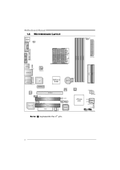
Motherboard Manual 1.5 MOTHERBOARD LAYOUT JKBMS1 JKBV1 JD DRII_ 22V JCOM1 DIMMB2 DIMMA2 DIMMB1 DIMMA1 Socket A M2 JVGA1 JPRN T1 J ATXPWR1 JUSB1 J USBV1 JUSBLAN1 J ATXPWR2 IDE1 IDE2 JAUDIO1 JFAUDIO1 Codec Super I/O JCFAN1 LAN GeForce 6100 BAT1 PCI-EX1_1 J CDIN1 PCI-EX16 PCI1 JSPDIF_OUT1 PCI2 FDD1 JSFAN2 LED_D1 LED_D2 JNFAN1 J USBV2 JUSB2 JUSB3 BIOS JSFAN1 PWRSW1 RSTSW2 nForce 410 JSATA2 JSATA1 (Optional)JCI1 JCMOS1 J PANEL1 IR (optional) Note: ■ represents the 1st pin. 4
Motherboard Manual 1.5 MOTHERBOARD LAYOUT JKBMS1 JKBV1 JD DRII_ 22V JCOM1 DIMMB2 DIMMA2 DIMMB1 DIMMA1 Socket A M2 JVGA1 JPRN T1 J ATXPWR1 JUSB1 J USBV1 JUSBLAN1 J ATXPWR2 IDE1 IDE2 JAUDIO1 JFAUDIO1 Codec Super I/O JCFAN1 LAN GeForce 6100 BAT1 PCI-EX1_1 J CDIN1 PCI-EX16 PCI1 JSPDIF_OUT1 PCI2 FDD1 JSFAN2 LED_D1 LED_D2 JNFAN1 J USBV2 JUSB2 JUSB3 BIOS JSFAN1 PWRSW1 RSTSW2 nForce 410 JSATA2 JSATA1 (Optional)JCI1 JCMOS1 J PANEL1 IR (optional) Note: ■ represents the 1st pin. 4
Setup Manual
Page 8
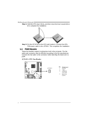
... the CPU FAN power cable to the fan manufacturer. Connect the fan cable to the connector while matching the black wire to complete the installation. Motherboard Manual Step 4: Hold the CPU down firmly, and then close the lever toward direct B to pin#1.
... the CPU FAN power cable to the fan manufacturer. Connect the fan cable to the connector while matching the black wire to complete the installation. Motherboard Manual Step 4: Hold the CPU down firmly, and then close the lever toward direct B to pin#1.
Setup Manual
Page 10
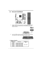
Unlock a DIMM slot by pressing the retaining clips outward. Motherboard Manual 2.3 INSTALLING SYSTEM MEMORY 1. Align a DIMM on the slot such that the notch on the DIMM matches the break on the Slot. 2. Memory Capacity DIMM Socket Location DDR Module DIMMA1 256MB/512MB/1024MB DIMMB1 256MB/512MB/1024MB DIMMA2 256MB/512MB/1024MB DIMMB2 256MB/512MB/1024MB Total Memory Size Max is properly seated. Insert the DIMM vertically and firmly into the slot until the retaining chip snap back in place and the DIMM is 4GB. 8 B.
Unlock a DIMM slot by pressing the retaining clips outward. Motherboard Manual 2.3 INSTALLING SYSTEM MEMORY 1. Align a DIMM on the slot such that the notch on the DIMM matches the break on the Slot. 2. Memory Capacity DIMM Socket Location DDR Module DIMMA1 256MB/512MB/1024MB DIMMB1 256MB/512MB/1024MB DIMMA2 256MB/512MB/1024MB DIMMB2 256MB/512MB/1024MB Total Memory Size Max is properly seated. Insert the DIMM vertically and firmly into the slot until the retaining chip snap back in place and the DIMM is 4GB. 8 B.
Setup Manual
Page 11
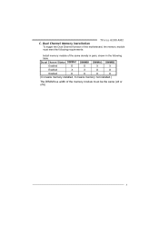
Dual Channel Memory installation To trigger the Dual Channel function of the same density in pairs, shown in the following table. TForce 6100 AM2 C. Duual Channel Status DIMMA1 DIMMB1 DIMMA2 DIMMB2 Enabled O O X X Enabled X X O O Enabled O O O O (O means memory installed, X means memory not installed.) The DRAM bus width of the memory module must meet the following requirements: Install memory module of the motherboard, the memory module must be the same (x8 or x16) 9
Dual Channel Memory installation To trigger the Dual Channel function of the same density in pairs, shown in the following table. TForce 6100 AM2 C. Duual Channel Status DIMMA1 DIMMB1 DIMMA2 DIMMB2 Enabled O O X X Enabled X X O O Enabled O O O O (O means memory installed, X means memory not installed.) The DRAM bus width of the memory module must meet the following requirements: Install memory module of the motherboard, the memory module must be the same (x8 or x16) 9
Setup Manual
Page 12
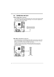
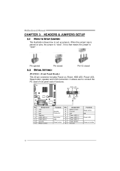
... to four hard disk drives. This connector supports the provided floppy drive ribbon cables. 33 1 34 2 IDE1/IDE2: Hard Disk Connectors The motherboard has a 32-bit Enhanced PCI IDE Controller that supports 360K, 720K, 1.2M, 1.44M and 2.88M floppy disk types. The IDE connectors ... IDE1. 40 39 2 1 IDE2 IDE1 10 It has two HDD connectors IDE1 (primary) and IDE2 (secondary). Motherboard Manual 2.4 CONNECTORS AND SLOTS FDD1: Floppy Disk Connector The motherboard provides a standard floppy disk connector that provides PIO Mode 0~4, Bus Master, and Ultra DMA 33/66/100/133 ...
... to four hard disk drives. This connector supports the provided floppy drive ribbon cables. 33 1 34 2 IDE1/IDE2: Hard Disk Connectors The motherboard has a 32-bit Enhanced PCI IDE Controller that supports 360K, 720K, 1.2M, 1.44M and 2.88M floppy disk types. The IDE connectors ... IDE1. 40 39 2 1 IDE2 IDE1 10 It has two HDD connectors IDE1 (primary) and IDE2 (secondary). Motherboard Manual 2.4 CONNECTORS AND SLOTS FDD1: Floppy Disk Connector The motherboard provides a standard floppy disk connector that provides PIO Mode 0~4, Bus Master, and Ultra DMA 33/66/100/133 ...
Setup Manual
Page 13
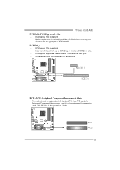
...-Express supports a raw bit-rate of 4GB/s simultaneously per direction; 500MB/s in total. - P CI -E X1_1 PC IE X16 PCI1~PCI2: Peripheral Component Interconnect Slots This motherboard is designated as 32 bits. PCI stands for Peripheral Component Interconnect, and it is a bus standard for an aggregate of 8GB/s totally. PCI1 PCI2 11... realized bandwidth of 2.5Gb/s on the data pins. - 2X bandwidth over the traditional PCI architecture. PCI-Express 1.0a compliant. - PCI-Ex1_1 - PCI-Express 1.0a compliant. - TForce 6100 AM2 PCI-Ex16: PCI-Express x16 Slot -
...-Express supports a raw bit-rate of 4GB/s simultaneously per direction; 500MB/s in total. - P CI -E X1_1 PC IE X16 PCI1~PCI2: Peripheral Component Interconnect Slots This motherboard is designated as 32 bits. PCI stands for Peripheral Component Interconnect, and it is a bus standard for an aggregate of 8GB/s totally. PCI1 PCI2 11... realized bandwidth of 2.5Gb/s on the data pins. - 2X bandwidth over the traditional PCI architecture. PCI-Express 1.0a compliant. - PCI-Ex1_1 - PCI-Express 1.0a compliant. - TForce 6100 AM2 PCI-Ex16: PCI-Express x16 Slot -
Setup Manual
Page 14
... button, speaker and IrDA Connection. When the jumper cap is placed on pins, the jumper is "close", if not, that means the jumper is "open". Motherboard Manual CHAPTER 3: HEADERS & JUMPERS SETUP 3.1 HOW TO SETUP JUMPERS The illustration shows how to connect the PC case's front panel switch functions.
... button, speaker and IrDA Connection. When the jumper cap is placed on pins, the jumper is "close", if not, that means the jumper is "open". Motherboard Manual CHAPTER 3: HEADERS & JUMPERS SETUP 3.1 HOW TO SETUP JUMPERS The illustration shows how to connect the PC case's front panel switch functions.
Setup Manual
Page 15
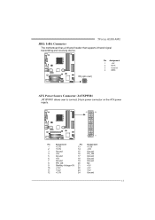
TForce 6100 AM2 JIR1: IrDA Connector The motherboard has a Infrared header that supports infrared signal transmitting and receiving device. IR(opt ional) 2 4 1 3 Pin Assignment 1 +5V 2 IRT X 3 Ground 4 IRRX ATX Power Source Connector: JATXPWR1 ...
TForce 6100 AM2 JIR1: IrDA Connector The motherboard has a Infrared header that supports infrared signal transmitting and receiving device. IR(opt ional) 2 4 1 3 Pin Assignment 1 +5V 2 IRT X 3 Ground 4 IRRX ATX Power Source Connector: JATXPWR1 ...
Setup Manual
Page 16
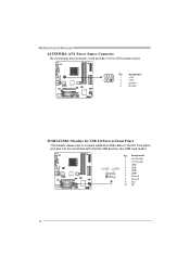
JUSB2 JUSB3 4 USB- 2 10 5 USB+ 6 USB+ 7 Ground 1 9 8 Ground 9 Key 10 NC 14 Pin Assignment 1 +5V (fused) 2 +5V (fused) 3 USB- Motherboard Manual JATXPWR2: ATX Power Source Connector By connecting this connector, it will provide +12V to CPU power circuit. 3 2 Pin 1 Assignment +12V 4 1 2 +12V 3 Ground 4 Ground JUSB2/JUSB3: Headers for USB 2.0 Ports at Front Panel This header allows user to connect additional USB cable on the PC front panel, and also can be connected with internal USB devices, like USB card reader.
JUSB2 JUSB3 4 USB- 2 10 5 USB+ 6 USB+ 7 Ground 1 9 8 Ground 9 Key 10 NC 14 Pin Assignment 1 +5V (fused) 2 +5V (fused) 3 USB- Motherboard Manual JATXPWR2: ATX Power Source Connector By connecting this connector, it will provide +12V to CPU power circuit. 3 2 Pin 1 Assignment +12V 4 1 2 +12V 3 Ground 4 Ground JUSB2/JUSB3: Headers for USB 2.0 Ports at Front Panel This header allows user to connect additional USB cable on the PC front panel, and also can be connected with internal USB devices, like USB card reader.
Setup Manual
Page 18
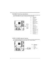
Motherboard Manual JFAUDIO1: Front Panel Audio Header This header allows user to connect the audio source from the variaty devices, like CD-ROM, DVD-ROM, PCI ...
Motherboard Manual JFAUDIO1: Front Panel Audio Header This header allows user to connect the audio source from the variaty devices, like CD-ROM, DVD-ROM, PCI ...
Setup Manual
Page 19
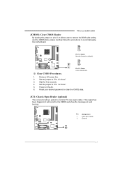
TForce 6100 AM2 JCMOS1: Clear CMOS Header By placing the jumper on next boot-up. Remove AC power line. 2. Set the jumper to avoid damaging the motherboard. 1 3 Pin 1-2 Close: Normal Operation (default). 1 1 3 Pin 2-3 Close: Clear CMOS data. ※ Clear CMOS Procedures: 1. If the signal has been triggered, it will record to the ...
TForce 6100 AM2 JCMOS1: Clear CMOS Header By placing the jumper on next boot-up. Remove AC power line. 2. Set the jumper to avoid damaging the motherboard. 1 3 Pin 1-2 Close: Normal Operation (default). 1 1 3 Pin 2-3 Close: Clear CMOS data. ※ Clear CMOS Procedures: 1. If the signal has been triggered, it will record to the ...
Setup Manual
Page 20
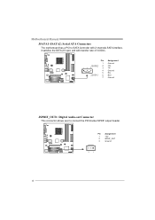
Motherboard Manual JSATA1~JSATA2: Serial ATA Connectors The motherboard has a PCI to connect the PCI bracket SPDIF output header. Pin Assignment 1 +5V 2 SPDIF_OUT 3 Ground 3 1 18 Pin 1 J SATA2 2 14 7 3 4 5 J SATA1 6 7 Assignment Ground TX+ TXGround RXRX+ Ground JSPDIF_OUT1: Digital Audio-out Connector This connector allows user to SATA Controller with 2 channels SATA interface, it satisfies the SATA 2.0 spec and with transfer rate of 3.0Gb/s.
Motherboard Manual JSATA1~JSATA2: Serial ATA Connectors The motherboard has a PCI to connect the PCI bracket SPDIF output header. Pin Assignment 1 +5V 2 SPDIF_OUT 3 Ground 3 1 18 Pin 1 J SATA2 2 14 7 3 4 5 J SATA1 6 7 Assignment Ground TX+ TXGround RXRX+ Ground JSPDIF_OUT1: Digital Audio-out Connector This connector allows user to SATA Controller with 2 channels SATA interface, it satisfies the SATA 2.0 spec and with transfer rate of 3.0Gb/s.
Setup Manual
Page 22
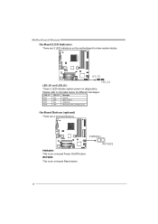
RSTSW2 20 On-Board Buttons (optional) There are 2 LED indicators on -board buttons. PWRSW1 PWRSW1: This is an on-board Reset button. RSTSW2: This is an on diagnostics. Please refer to show system status. Motherboard Manual On-Board LED Indicators There are 2 on the motherboard to the table below for different messages: LED_D1 ON ON OFF OFF LED_D2 ON OFF ON OFF Message Norm al Mem ory Error VGA Error Abnormal: CPU / Chipset error. LED_D1 LED_D2 LED_D1 and LED_D2: These 2 LED indicate system power on -board Power On/Off button.
RSTSW2 20 On-Board Buttons (optional) There are 2 LED indicators on -board buttons. PWRSW1 PWRSW1: This is an on-board Reset button. RSTSW2: This is an on diagnostics. Please refer to show system status. Motherboard Manual On-Board LED Indicators There are 2 on the motherboard to the table below for different messages: LED_D1 ON ON OFF OFF LED_D2 ON OFF ON OFF Message Norm al Mem ory Error VGA Error Abnormal: CPU / Chipset error. LED_D1 LED_D2 LED_D1 and LED_D2: These 2 LED indicate system power on -board Power On/Off button.
Setup Manual
Page 24
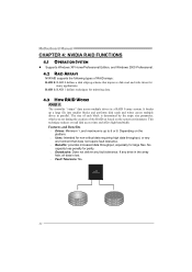
... stripe size parameter, which you set based on the platform. Uses: Intended for non-critical data requiring high data throughput, or any fault tolerance. Motherboard Manual CHAPTER 4: NVIDIA RAID FUNCTIONS 4.1 OPERATION SYSTEM z Supports Windows XP Home/Professional Edition, and Windows 2000 Professional. 4.2 RAID ARRAYS NVRAID supports the following types of...
... stripe size parameter, which you set based on the platform. Uses: Intended for non-critical data requiring high data throughput, or any fault tolerance. Motherboard Manual CHAPTER 4: NVIDIA RAID FUNCTIONS 4.1 OPERATION SYSTEM z Supports Windows XP Home/Professional Edition, and Windows 2000 Professional. 4.2 RAID ARRAYS NVRAID supports the following types of...
Setup Manual
Page 26
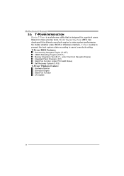
Motherboard Manual 5.1: T-POWER INTRODUCTION Biostar T-Power is a whole new utility that is able to present the best system state according to raise system performance. T-Power BIOS Features: Overclocking Navigator Engine (O.N.E.) ... under PC Health Status) Self Recovery System (S.R.S) T-Power Windows Feature: Hardware Monitor Overclock Engine Smart Fan Function Life Update 24 Based on many precise tests, Biostar Engineering Team (BET) has developed this ultimate overclock engine to users' overclock setting.
Motherboard Manual 5.1: T-POWER INTRODUCTION Biostar T-Power is a whole new utility that is able to present the best system state according to raise system performance. T-Power BIOS Features: Overclocking Navigator Engine (O.N.E.) ... under PC Health Status) Self Recovery System (S.R.S) T-Power Windows Feature: Hardware Monitor Overclock Engine Smart Fan Function Life Update 24 Based on many precise tests, Biostar Engineering Team (BET) has developed this ultimate overclock engine to users' overclock setting.
Setup Manual
Page 28
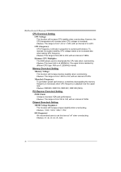
...-Express Overclock Setting: PCIE Clock: It helps to be increased also when raising CPU frequency. CPU Frequency: CPU Frequency is adjusted over the upper limit. Motherboard Manual CPU Overclock Setting: CPU Voltage: This function will increase memory stability when overclocking. Choices: This range is increased. Memory Overclock Setting: Memory Voltage: This...
...-Express Overclock Setting: PCIE Clock: It helps to be increased also when raising CPU frequency. CPU Frequency: CPU Frequency is adjusted over the upper limit. Motherboard Manual CPU Overclock Setting: CPU Voltage: This function will increase memory stability when overclocking. Choices: This range is increased. Memory Overclock Setting: Memory Voltage: This...
Setup Manual
Page 30
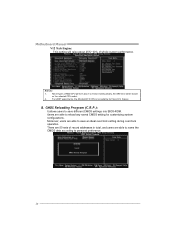
... Program (C.R.P.): It allows users to save different CMOS settings into BIOS-ROM. Notices: 1. B. Users are able to save an ideal overclock setting during overclock operation. Motherboard Manual V12 Tech Engine: This setting will be based on the selected CPU model. 2. From BET experiments, the Atholon64 FX CPU is not suitable for...
... Program (C.R.P.): It allows users to save different CMOS settings into BIOS-ROM. Notices: 1. B. Users are able to save an ideal overclock setting during overclock operation. Motherboard Manual V12 Tech Engine: This setting will be based on the selected CPU model. 2. From BET experiments, the Atholon64 FX CPU is not suitable for...


