
Setup Manual
Page 1
There is no representations or warranties with the instructions, may cause harmful interference to notify any purpose. The content of this user's manual is not allowed without notice and we will not occur in a particular installation. The vendor makes no guarantee that interference ... names are designed to Part 15 of this publication, in part or in whole, is subject to revise this user's manual. Duplication of the FCC Rules. TForce 6100 AM2 Setup Manual FCC Information and Copyright This equipment has been tested and found in this publication and to make changes to the ...
There is no representations or warranties with the instructions, may cause harmful interference to notify any purpose. The content of this user's manual is not allowed without notice and we will not occur in a particular installation. The vendor makes no guarantee that interference ... names are designed to Part 15 of this publication, in part or in whole, is subject to revise this user's manual. Duplication of the FCC Rules. TForce 6100 AM2 Setup Manual FCC Information and Copyright This equipment has been tested and found in this publication and to make changes to the ...
Setup Manual
Page 3
Hold the board on motherboard or the rear side of the board unless necessary. CHAPTER 1: INTRODUCTION TForce 6100 AM2 1.1 BEFORE YOU START Thank you take the motherboard out from anti-static bag, ground yourself properly by touching any safely grounded appliance, or use grounded ... parts will cause short circuits which may damage the equipment. „ Keep the computer from power outlet before operation. „ Before you for ATX Case X 1 User's Manual X 1 Fully Setup Driver CD X 1 USB 2.0 Cable X1 (optional) S/PDIF out Cable X 1 (optional) 1
Hold the board on motherboard or the rear side of the board unless necessary. CHAPTER 1: INTRODUCTION TForce 6100 AM2 1.1 BEFORE YOU START Thank you take the motherboard out from anti-static bag, ground yourself properly by touching any safely grounded appliance, or use grounded ... parts will cause short circuits which may damage the equipment. „ Keep the computer from power outlet before operation. „ Before you for ATX Case X 1 User's Manual X 1 Fully Setup Driver CD X 1 USB 2.0 Cable X1 (optional) S/PDIF out Cable X 1 (optional) 1
Setup Manual
Page 14
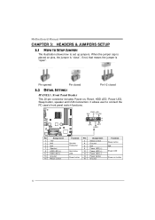
It allows user to set up jumpers. PWR_LED SLP On/Off ++ - 2 16 1 +- 15 SPK RST HLE D Pin Assignment 1 +5V 3 N/A 5 N/A 7 Speaker 9 HDD LED (+) 11 HDD LED (-) 13 Ground 15 ... and IrDA Connection. Pin opened Pin closed Pin1-2 closed 3.2 DETAIL SETTINGS JPANEL1: Front Panel Header This 20-pin connector includes Power-on button 12 Motherboard Manual CHAPTER 3: HEADERS & JUMPERS SETUP 3.1 HOW TO SETUP JUMPERS The illustration shows how to connect the PC case's front panel switch functions. When the jumper cap...
It allows user to set up jumpers. PWR_LED SLP On/Off ++ - 2 16 1 +- 15 SPK RST HLE D Pin Assignment 1 +5V 3 N/A 5 N/A 7 Speaker 9 HDD LED (+) 11 HDD LED (-) 13 Ground 15 ... and IrDA Connection. Pin opened Pin closed Pin1-2 closed 3.2 DETAIL SETTINGS JPANEL1: Front Panel Header This 20-pin connector includes Power-on button 12 Motherboard Manual CHAPTER 3: HEADERS & JUMPERS SETUP 3.1 HOW TO SETUP JUMPERS The illustration shows how to connect the PC case's front panel switch functions. When the jumper cap...
Setup Manual
Page 16
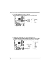
Pin Assignment 1 +5V (fused) 2 +5V (fused) 3 USB- JUSB2 JUSB3 4 USB- 2 10 5 USB+ 6 USB+ 7 Ground 1 9 8 Ground 9 Key 10 NC 14 Motherboard Manual JATXPWR2: ATX Power Source Connector By connecting this connector, it will provide +12V to CPU power circuit. 3 2 Pin 1 Assignment +12V 4 1 2 +12V 3 Ground 4 Ground JUSB2/JUSB3: Headers for USB 2.0 Ports at Front Panel This header allows user to connect additional USB cable on the PC front panel, and also can be connected with internal USB devices, like USB card reader.
Pin Assignment 1 +5V (fused) 2 +5V (fused) 3 USB- JUSB2 JUSB3 4 USB- 2 10 5 USB+ 6 USB+ 7 Ground 1 9 8 Ground 9 Key 10 NC 14 Motherboard Manual JATXPWR2: ATX Power Source Connector By connecting this connector, it will provide +12V to CPU power circuit. 3 2 Pin 1 Assignment +12V 4 1 2 +12V 3 Ground 4 Ground JUSB2/JUSB3: Headers for USB 2.0 Ports at Front Panel This header allows user to connect additional USB cable on the PC front panel, and also can be connected with internal USB devices, like USB card reader.
Setup Manual
Page 18
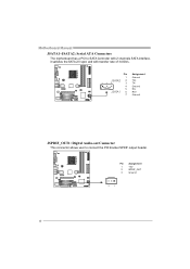
... speaker Right 13 Left line in/ Rear speaker Left 14 Left line in/ Rear speaker Left JCDIN1: CD-ROM Audio-in Connector This connector allows user to connect the front audio output cable with the PC front panel. It will disable the output on back panel audio connectors. Motherboard... Manual JFAUDIO1: Front Panel Audio Header This header allows user to connect the audio source from the variaty devices, like CD-ROM, DVD-ROM, PCI sound card, PCI TV turner card...
... speaker Right 13 Left line in/ Rear speaker Left 14 Left line in/ Rear speaker Left JCDIN1: CD-ROM Audio-in Connector This connector allows user to connect the front audio output cable with the PC front panel. It will disable the output on back panel audio connectors. Motherboard... Manual JFAUDIO1: Front Panel Audio Header This header allows user to connect the audio source from the variaty devices, like CD-ROM, DVD-ROM, PCI sound card, PCI TV turner card...
Setup Manual
Page 20
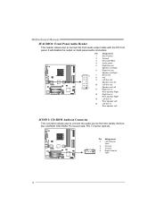
Pin Assignment 1 +5V 2 SPDIF_OUT 3 Ground 3 1 18 Motherboard Manual JSATA1~JSATA2: Serial ATA Connectors The motherboard has a PCI to connect the PCI bracket SPDIF output header. Pin 1 J SATA2 2 14 7 3 4 5 J SATA1 6 7 Assignment Ground TX+ TXGround RXRX+ Ground JSPDIF_OUT1: Digital Audio-out Connector This connector allows user to SATA Controller with 2 channels SATA interface, it satisfies the SATA 2.0 spec and with transfer rate of 3.0Gb/s.
Pin Assignment 1 +5V 2 SPDIF_OUT 3 Ground 3 1 18 Motherboard Manual JSATA1~JSATA2: Serial ATA Connectors The motherboard has a PCI to connect the PCI bracket SPDIF output header. Pin 1 J SATA2 2 14 7 3 4 5 J SATA1 6 7 Assignment Ground TX+ TXGround RXRX+ Ground JSPDIF_OUT1: Digital Audio-out Connector This connector allows user to SATA Controller with 2 channels SATA interface, it satisfies the SATA 2.0 spec and with transfer rate of 3.0Gb/s.
Setup Manual
Page 26
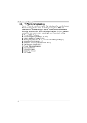
... Team (BET) has developed this ultimate overclock engine to users' overclock setting. Motherboard Manual 5.1: T-POWER INTRODUCTION Biostar T-Power is a whole new utility that is able to present the best system state according to raise system performance. No matter whether under PC Health ... Reloading Program (C.R.P.) Memory Integration Test (M.I.T., under Overclock Navigator Engine) Integrated Flash Program (I.F.P.) Smart Fan Function (under BIOS or Windows interface, T-Power is designed for overclock users.
... Team (BET) has developed this ultimate overclock engine to users' overclock setting. Motherboard Manual 5.1: T-POWER INTRODUCTION Biostar T-Power is a whole new utility that is able to present the best system state according to raise system performance. No matter whether under PC Health ... Reloading Program (C.R.P.) Memory Integration Test (M.I.T., under Overclock Navigator Engine) Integrated Flash Program (I.F.P.) Smart Fan Function (under BIOS or Windows interface, T-Power is designed for overclock users.
Setup Manual
Page 27
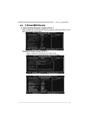
Manual Overclock System (M.O.S.) MOS is designed for both Elite and Casual overclockers. Overclocking Navigator Engine (O.N.E.): ONE provides two powerful overclocking engines: MOS and AOS for experienced overclock users. It allows users to customize personal overclock settings. 25 TForce 6100 AM2 5.2: T-POWER BIOS FEATURE A.
Manual Overclock System (M.O.S.) MOS is designed for both Elite and Casual overclockers. Overclocking Navigator Engine (O.N.E.): ONE provides two powerful overclocking engines: MOS and AOS for experienced overclock users. It allows users to customize personal overclock settings. 25 TForce 6100 AM2 5.2: T-POWER BIOS FEATURE A.
Setup Manual
Page 28
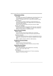
...function will increase chipset stability when overclocking. Choices: DDR400, DDR 533, DDR 667, DDR 800 (MHz). Hammer CPU Multiplier: The MOS allows users to system performance. PCI-Express Overclock Setting: PCIE Clock: It helps to set this item at "x4" when overclocking. Choices: 1.52V,...interval. The upper limit is increased. HT Frequency: We recommend users to increase VGA card performance. To maintain the system stability, CPU voltage needs to 1.725V, with an interval of 1MHz. Motherboard Manual CPU Overclock Setting: CPU Voltage: This function will increase when...
...function will increase chipset stability when overclocking. Choices: DDR400, DDR 533, DDR 667, DDR 800 (MHz). Hammer CPU Multiplier: The MOS allows users to system performance. PCI-Express Overclock Setting: PCIE Clock: It helps to set this item at "x4" when overclocking. Choices: 1.52V,...interval. The upper limit is increased. HT Frequency: We recommend users to increase VGA card performance. To maintain the system stability, CPU voltage needs to 1.725V, with an interval of 1MHz. Motherboard Manual CPU Overclock Setting: CPU Voltage: This function will increase when...
Setup Manual
Page 30
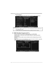
...Manual V12 Tech Engine: This setting will be based on the selected CPU model. 2. There are able to save an ideal overclock setting during overclock operation. Not all types of AMD CPU perform above overclock setting ideally; B. CMOS Reloading Program (C.R.P.): It allows users to save different CMOS settings into BIOS-ROM. feature. Users... are able to name the CMOS data according to reload any saved CMOS setting for this A.O.S. Moreover, users are 50 sets of whole...
...Manual V12 Tech Engine: This setting will be based on the selected CPU model. 2. There are able to save an ideal overclock setting during overclock operation. Not all types of AMD CPU perform above overclock setting ideally; B. CMOS Reloading Program (C.R.P.): It allows users to save different CMOS settings into BIOS-ROM. feature. Users... are able to name the CMOS data according to reload any saved CMOS setting for this A.O.S. Moreover, users are 50 sets of whole...
Setup Manual
Page 36
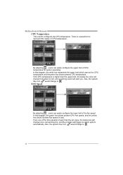
Motherboard Manual CPU Temperature This column configures the CPU temperature. If any ). If the CPU temperature is lower than the upper limit, the status line color will change into a red warning line, and the program will alert you. FAN Speed By adjusting , users can easily configure the upper... to red, and a warning sound will trigger an alarm system automatically. In this diagram, the white line represents the upper limit which user-set value, the status line will change from green to represent the status of the fan speed. Also, the system tray icon would change...
Motherboard Manual CPU Temperature This column configures the CPU temperature. If any ). If the CPU temperature is lower than the upper limit, the status line color will change into a red warning line, and the program will alert you. FAN Speed By adjusting , users can easily configure the upper... to red, and a warning sound will trigger an alarm system automatically. In this diagram, the white line represents the upper limit which user-set value, the status line will change from green to represent the status of the fan speed. Also, the system tray icon would change...
Setup Manual
Page 38
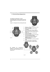
...for T-series Overclocking utility. Clicking on this button to reset all the overclock features to the Biostar Homepage. B. C. Click on "Biostar" will pop-up . Click on this button and the utility will lead you to default ...up 4 sub-screens (Please refers to an optimal level. E. H. By adjusting the overclocking features in 4 sub-screens, users can tune the system performance to Graphic 3). Graphic 2 Graphic 1 A. D. F. Friendly interface and solid overclock features are ...This column shows present CPU speed and overclocking percentage. Motherboard Manual B. Graphic 3 36
...for T-series Overclocking utility. Clicking on this button to reset all the overclock features to the Biostar Homepage. B. C. Click on "Biostar" will pop-up . Click on this button and the utility will lead you to default ...up 4 sub-screens (Please refers to an optimal level. E. H. By adjusting the overclocking features in 4 sub-screens, users can tune the system performance to Graphic 3). Graphic 2 Graphic 1 A. D. F. Friendly interface and solid overclock features are ...This column shows present CPU speed and overclocking percentage. Motherboard Manual B. Graphic 3 36
Setup Manual
Page 67
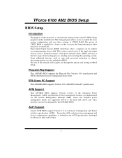
TForce 6100 AM2 BIOS Setup BIOS Setup Introduction The purpose of the booting process, loading and executing the...BIOS supports Version 1.1&1.2 of CMOS RAM is turned off. Power to CMOS RAM. This system controls most of this manual will to describe the settings in the ACPI specification, developed by a battery so that it retains the Setup information ...features, such as defined in the Award™ BIOS Setup program on this AWARD BIOS. The Setup program allows users to modify the basic system configuration and save these settings to the hard disk drives and video monitors can do ...
TForce 6100 AM2 BIOS Setup BIOS Setup Introduction The purpose of the booting process, loading and executing the...BIOS supports Version 1.1&1.2 of CMOS RAM is turned off. Power to CMOS RAM. This system controls most of this manual will to describe the settings in the ACPI specification, developed by a battery so that it retains the Setup information ...features, such as defined in the Award™ BIOS Setup program on this AWARD BIOS. The Setup program allows users to modify the basic system configuration and save these settings to the hard disk drives and video monitors can do ...
Setup Manual
Page 95
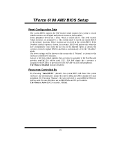
...Legacy is the term, which signifies that a resource is assigned to the ISA Bus and provides non-PnP ISA add-on cards. TForce 6100 AM2 BIOS Setup Reset Configuration Data The system BIOS supports the PnP feature which requires the system to record which resources are assigned to it...assign IRQ & DMA for the resources controlled by function. These locations are no IRQ/DMA and I/O port conflicts. By Choosing "Manual", the user will update only when the new configuration varies from conflict. The above settings will detect the system resources and automatically assign the relative ...
...Legacy is the term, which signifies that a resource is assigned to the ISA Bus and provides non-PnP ISA add-on cards. TForce 6100 AM2 BIOS Setup Reset Configuration Data The system BIOS supports the PnP feature which requires the system to record which resources are assigned to it...assign IRQ & DMA for the resources controlled by function. These locations are no IRQ/DMA and I/O port conflicts. By Choosing "Manual", the user will update only when the new configuration varies from conflict. The above settings will detect the system resources and automatically assign the relative ...
Setup Manual
Page 100
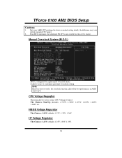
Manual Overclock System (M.O.S.) MOS is not suitable for experienced overclock users. Not every AMD CPU performs the above overclock setting ideally; the overclock function achieved the best performance on our test results; TForce 6100 AM2 BIOS Setup Cautions: 1. the difference may vary with the installed CPU model. 2. From BET experiment, the Atholon64 FX CPU is designed...
Manual Overclock System (M.O.S.) MOS is not suitable for experienced overclock users. Not every AMD CPU performs the above overclock setting ideally; the overclock function achieved the best performance on our test results; TForce 6100 AM2 BIOS Setup Cautions: 1. the difference may vary with the installed CPU model. 2. From BET experiment, the Atholon64 FX CPU is designed...


