
Setup Manual
Page 2
... Checklist 1 1.3 Motherboard Features 2 1.4 Rear Panel Connectors (Ver 5.x 4 1.5 Rear Panel Connectors (Ver 6.x 4 1.6 Motherboard Layout 5 Chapter 2: Hardware Installation 6 2.1 Installing Central Processing Unit (CPU 6 2.2 FAN Headers 8 2.3 Installing System Memory 9 2.4 Connectors and Slots 11 Chapter 3: Headers & Jumpers Setup 13 3.1 How to Setup Jumpers 13 3.2 Detail Settings 13 Chapter 4: NVIDIA RAID Functions 20 4.1 Operation System 20...
... Checklist 1 1.3 Motherboard Features 2 1.4 Rear Panel Connectors (Ver 5.x 4 1.5 Rear Panel Connectors (Ver 6.x 4 1.6 Motherboard Layout 5 Chapter 2: Hardware Installation 6 2.1 Installing Central Processing Unit (CPU 6 2.2 FAN Headers 8 2.3 Installing System Memory 9 2.4 Connectors and Slots 11 Chapter 3: Headers & Jumpers Setup 13 3.1 How to Setup Jumpers 13 3.2 Detail Settings 13 Chapter 4: NVIDIA RAID Functions 20 4.1 Operation System 20...
Setup Manual
Page 4
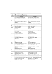
... / 800 Registered DIMM and ECC DIMM is not supported DIMM Slots x 4 Each DIMM supports 256/512MB & 1GB/2GB DDR2 Max Memory Capicity 8GB Dual Channel Mode DDR2 memory module Supports DDR2 533 / 667 / 800 Registered DIMM and ECC DIMM is for RTL 8110SC only) Half / Full duplex capability Half.../ 66 / 100 / 133 Bus Master Mode Ultra DMA 33 / 66 / 100 / 133 Bus Master Mode supports PIO Mode 0~4. Motherboard Manual 1.3 MOTHERBOARD FEATURES TF520 A2+ TF560 A2+ Socket AM2 / AM2+ (By BIOS update) Socket AM2 / AM2+ (By BIOS update) AMD Athlon 64 / Athlon 64 x2 / Sempron AMD Athlon 64 / Athlon...
... / 800 Registered DIMM and ECC DIMM is not supported DIMM Slots x 4 Each DIMM supports 256/512MB & 1GB/2GB DDR2 Max Memory Capicity 8GB Dual Channel Mode DDR2 memory module Supports DDR2 533 / 667 / 800 Registered DIMM and ECC DIMM is for RTL 8110SC only) Half / Full duplex capability Half.../ 66 / 100 / 133 Bus Master Mode Ultra DMA 33 / 66 / 100 / 133 Bus Master Mode supports PIO Mode 0~4. Motherboard Manual 1.3 MOTHERBOARD FEATURES TF520 A2+ TF560 A2+ Socket AM2 / AM2+ (By BIOS update) Socket AM2 / AM2+ (By BIOS update) AMD Athlon 64 / Athlon 64 x2 / Sempron AMD Athlon 64 / Athlon...

Setup Manual
Page 11
Insert the DIMM vertically and firmly into the slot until the retaining chip snap back in place and the DIMM is 8GB. 9 2.3 INSTALLING SYSTEM MEMORY A. Unlock a DIMM slot by pressing the retaining clips outward. Memory Modules TF520 A2+/TF560 A2+ DIMMA1 DIMMB1 DIMMA2 DIMMB2 1. Align a DIMM on the slot such that the notch on the DIMM matches the break on the Slot. 2. Memory Capacity DIMM Socket Location DIMMA1 DIMMB1 DIMMA2 DIMMB2 DDR2 Module 256MB/512MB/1GB/2GB 256MB/512MB/1GB/2GB 256MB/512MB/1GB/2GB 256MB/512MB/1GB/2GB Total Memory Size Max is properly seated. B.
Insert the DIMM vertically and firmly into the slot until the retaining chip snap back in place and the DIMM is 8GB. 9 2.3 INSTALLING SYSTEM MEMORY A. Unlock a DIMM slot by pressing the retaining clips outward. Memory Modules TF520 A2+/TF560 A2+ DIMMA1 DIMMB1 DIMMA2 DIMMB2 1. Align a DIMM on the slot such that the notch on the DIMM matches the break on the Slot. 2. Memory Capacity DIMM Socket Location DIMMA1 DIMMB1 DIMMA2 DIMMB2 DDR2 Module 256MB/512MB/1GB/2GB 256MB/512MB/1GB/2GB 256MB/512MB/1GB/2GB 256MB/512MB/1GB/2GB Total Memory Size Max is properly seated. B.

Setup Manual
Page 12
Motherboard Manual C. Duual Channel Status DIMMA1 DIMMB1 DIMMA2 DIMMB2 Enabled O O X X Enabled X X O O Enabled O O O O (O means memory installed, X means memory not installed.) The DRAM bus width of the same density in pairs, shown in the following requirements: Install memory module of the memory module must be the same (x8 or x16) 10 Dual Channel Memory installation To trigger the Dual Channel function of the motherboard, the memory module must meet the following table.
Motherboard Manual C. Duual Channel Status DIMMA1 DIMMB1 DIMMA2 DIMMB2 Enabled O O X X Enabled X X O O Enabled O O O O (O means memory installed, X means memory not installed.) The DRAM bus width of the same density in pairs, shown in the following requirements: Install memory module of the memory module must be the same (x8 or x16) 10 Dual Channel Memory installation To trigger the Dual Channel function of the motherboard, the memory module must meet the following table.

Setup Manual
Page 20
...: These 2 LED indicate system power on the motherboard to the table below for different messages: LED_D1 LED_D2 Message ON ON OFF OFF ON Normal OFF Memory Error ON VGA Error OFF Abnormal: CPU / Chipset error. 18
...: These 2 LED indicate system power on the motherboard to the table below for different messages: LED_D1 LED_D2 Message ON ON OFF OFF ON Normal OFF Memory Error ON VGA Error OFF Abnormal: CPU / Chipset error. 18

Setup Manual
Page 26
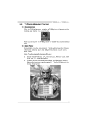
.... The BIOS information described below in the Setup CD. 24 T-Power BIOS Features: Overclocking Navigator Engine (O.N.E.) CMOS Reloading Program (C.R.P.) Memory Integration Test (M.I.T., under Overclock Navigator Engine) Integrated Flash Program (I.F.P.) Self Recovery System (S.R.S) Smart Fan Function (under BIOS or Windows ...best system state according to raise system performance. Motherboard Manual CHAPTER 5: OVERCLOCK QUICK GUIDE 5.1 T-POWER INTRODUCTION Biostar T-Power is a whole new utility that is designed for your reference only and the actual BIOS information and settings on ...
.... The BIOS information described below in the Setup CD. 24 T-Power BIOS Features: Overclocking Navigator Engine (O.N.E.) CMOS Reloading Program (C.R.P.) Memory Integration Test (M.I.T., under Overclock Navigator Engine) Integrated Flash Program (I.F.P.) Self Recovery System (S.R.S) Smart Fan Function (under BIOS or Windows ...best system state according to raise system performance. Motherboard Manual CHAPTER 5: OVERCLOCK QUICK GUIDE 5.1 T-POWER INTRODUCTION Biostar T-Power is a whole new utility that is designed for your reference only and the actual BIOS information and settings on ...

Setup Manual
Page 28
...the HyperTransport speed of CPU to northbridge chipset. Please disable this option when proceeding overclocking. CPU Voltage: This function will increase memory stability when overclocking. 26 NPT Fid Control: This function allows you to northbridge chipset. K8NB HT Width: This option controls the... HyperTransport width of CPU to reduce the EMI of CPU. HT Spread Spectrum: Please disable this option when proceeding overclocking. Memory Voltage: This function will increase CPU stability when overclocking. CPU Frequency: CPU Frequency is increased. PCIE Clock: It helps to ...
...the HyperTransport speed of CPU to northbridge chipset. Please disable this option when proceeding overclocking. CPU Voltage: This function will increase memory stability when overclocking. 26 NPT Fid Control: This function allows you to northbridge chipset. K8NB HT Width: This option controls the... HyperTransport width of CPU to reduce the EMI of CPU. HT Spread Spectrum: Please disable this option when proceeding overclocking. Memory Voltage: This function will increase CPU stability when overclocking. CPU Frequency: CPU Frequency is increased. PCIE Clock: It helps to ...

Setup Manual
Page 31
... "Overclocking Navigator Engine" item. Step 3: When the process is done, change the setting back from CMOS setup and reboot the system to ensure the memory stability. TF520 A2+/TF560 A2+ C. Memory Integration Test (M.I.T.): This function is "Disabled"; the condition parameter should be changed to "Enable" to proceed this test. ↓ Step 2: Save and Exit from...
... "Overclocking Navigator Engine" item. Step 3: When the process is done, change the setting back from CMOS setup and reboot the system to ensure the memory stability. TF520 A2+/TF560 A2+ C. Memory Integration Test (M.I.T.): This function is "Disabled"; the condition parameter should be changed to "Enable" to proceed this test. ↓ Step 2: Save and Exit from...
Setup Manual
Page 35
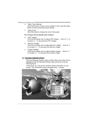
.... Please refer to the following figure; Display the CPU Speed, CPU external clock, Memory clock, VGA clock, and PCI clock information. Desktop Icon After the T-Utility has been installed, a T-Utility icon will be launched. 5.3 T-POWER WINDOWS FEATURE TF520 A2+/TF560 A2+ 1. Main Panel If you double-click the desktop icon, T-Utility will appear on...
.... Please refer to the following figure; Display the CPU Speed, CPU external clock, Memory clock, VGA clock, and PCI clock information. Desktop Icon After the T-Utility has been installed, a T-Utility icon will be launched. 5.3 T-POWER WINDOWS FEATURE TF520 A2+/TF560 A2+ 1. Main Panel If you double-click the desktop icon, T-Utility will appear on...
Setup Manual
Page 38
...Click this panel, you can get the real-time status information of the panel. Click on "+" to increase or "-" to decrease the Memory voltage. c. "Chipset Voltage": This function allows user to adjust CPU voltage. "CPU Voltage": This function allows user to adjust Chipset voltage.... The information will be highlighted and the Hardware Monitor panel will be refreshed every 1 second. 36 Overvoltage Panel contains these features: a. "Memory Voltage": This function allows user to decrease the Chipset voltage. 4. b. In this button to load a previously saved setting. Click on "+"...
...Click this panel, you can get the real-time status information of the panel. Click on "+" to increase or "-" to decrease the Memory voltage. c. "Chipset Voltage": This function allows user to adjust CPU voltage. "CPU Voltage": This function allows user to adjust Chipset voltage.... The information will be highlighted and the Hardware Monitor panel will be refreshed every 1 second. 36 Overvoltage Panel contains these features: a. "Memory Voltage": This function allows user to decrease the Chipset voltage. 4. b. In this button to load a previously saved setting. Click on "+"...
Setup Manual
Page 41
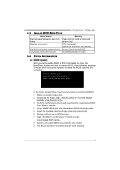
...the Biostar website: www.biostar.com.tw 3. The BIOS has been recovered and will update BIOS automatically and restart. 9. Make a bootable floppy disk. 2. Insert the bootable disk into floppy disk. 5. System will work properly. 39 Copy "AWDFLASH.exe" and respectively BIOS into floppy drive and press Enter. 6. TF520 A2+/TF560 A2+... to restore the BIOS: 1. If the following message is invaded by two short Video card not found or video card beeps memory bad High-low siren sound CPU overheated System will boot-up No error found during POST Long beeps every other second No DRAM...
...the Biostar website: www.biostar.com.tw 3. The BIOS has been recovered and will update BIOS automatically and restart. 9. Make a bootable floppy disk. 2. Insert the bootable disk into floppy disk. 5. System will work properly. 39 Copy "AWDFLASH.exe" and respectively BIOS into floppy drive and press Enter. 6. TF520 A2+/TF560 A2+... to restore the BIOS: 1. If the following message is invaded by two short Video card not found or video card beeps memory bad High-low siren sound CPU overheated System will boot-up No error found during POST Long beeps every other second No DRAM...

Setup Manual
Page 67
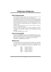
Set User Password If the Supervisor Password is set , then the User Password will not be prompted with to CMOS (memory) and exit setup. Exit Without Saving Abandon all configuration changes to enter a password. If the Supervisor Password is set and.... Save & Exit Setup Save all changes made during the current session and exit setup. You will be displayed before proceeding. 5 TF520 A2+/TF560 A2+ Set Supervisor Password Setting the supervisor password will be displayed before proceeding. Confirmation message will be able to change them. Confirmation message will ...
Set User Password If the Supervisor Password is set , then the User Password will not be prompted with to CMOS (memory) and exit setup. Exit Without Saving Abandon all configuration changes to enter a password. If the Supervisor Password is set and.... Save & Exit Setup Save all changes made during the current session and exit setup. You will be displayed before proceeding. 5 TF520 A2+/TF560 A2+ Set Supervisor Password Setting the supervisor password will be displayed before proceeding. Confirmation message will be able to change them. Confirmation message will ...

Setup Manual
Page 70
... the BIOS to stop the POST process and notify you. Displays the amount of floppy disk drive installed in your system. TF520 A2+/TF560 A2+ Item Drive A Halt On Base Memory Extended Memory Total Memory Options 360K, 5.25 in 1.2M, 5.25 in 720K, 3.5 in 1.44M, 3.5 in 2.88M, 3.5 in None All Errors No Errors All, but Keyboard...
... the BIOS to stop the POST process and notify you. Displays the amount of floppy disk drive installed in your system. TF520 A2+/TF560 A2+ Item Drive A Halt On Base Memory Extended Memory Total Memory Options 360K, 5.25 in 1.2M, 5.25 in 720K, 3.5 in 1.44M, 3.5 in 2.88M, 3.5 in None All Errors No Errors All, but Keyboard...

Setup Manual
Page 72
Enabled (default) Enable cache. Disab led Disable cache. Boot Seq & Floppy Setup This item allows you may improve performance. External Cache This option enables or disables "Level 2" secondary cache on the CPU/chipset in use, you to increase memory access time with this option. Enabled (default) Enable cache. Disab led Disable cache. TF520 A2+/TF560 A2+ CPU Internal Cache Depending on the CPU, which may be able to setup boot sequence & Floppy. 10
Enabled (default) Enable cache. Disab led Disable cache. Boot Seq & Floppy Setup This item allows you may improve performance. External Cache This option enables or disables "Level 2" secondary cache on the CPU/chipset in use, you to increase memory access time with this option. Enabled (default) Enable cache. Disab led Disable cache. TF520 A2+/TF560 A2+ CPU Internal Cache Depending on the CPU, which may be able to setup boot sequence & Floppy. 10

Setup Manual
Page 77
... this computer. Summary Screen Show This item allows you to the operating system. The Choices: Enabled (default), Disabled. The Choices: Non-OS2 (default), OS2. TF520 A2+/TF560 A2+ APIC MODE Selecting Enabled enables APIC device mode reporting from the BIOS to enable/disable the summary screen. Full Screen LOGO Show This item allows... you to select whether the "Small Logo" shows. OS Select For DRAM > 64MB A choice other than Non-OS2 is only used for OS2 systems with memory exceeding 64MB. Enabled (default) "Small Logo" shows when system boots up.
... this computer. Summary Screen Show This item allows you to the operating system. The Choices: Enabled (default), Disabled. The Choices: Non-OS2 (default), OS2. TF520 A2+/TF560 A2+ APIC MODE Selecting Enabled enables APIC device mode reporting from the BIOS to enable/disable the summary screen. Full Screen LOGO Show This item allows... you to select whether the "Small Logo" shows. OS Select For DRAM > 64MB A choice other than Non-OS2 is only used for OS2 systems with memory exceeding 64MB. Enabled (default) "Small Logo" shows when system boots up.

Setup Manual
Page 78
This chipset manage bus speeds and access to system memory resources, such as DRAM. The Choices: Enabled (default), Disabled. 16 The Choices: Disabled (default), Enabled. It also coordinates communications with your system. SSE/SSE2 instructions ... default settings that the settings have been optimized and therefore should not be changed unless you are suspicious that came with the PCI bus. TF520 A2+/TF560 A2+ 4 Advanced Chipset Features This submenu allows you to enable/disable SSE/SSE2 instruction.
This chipset manage bus speeds and access to system memory resources, such as DRAM. The Choices: Enabled (default), Disabled. 16 The Choices: Disabled (default), Enabled. It also coordinates communications with your system. SSE/SSE2 instructions ... default settings that the settings have been optimized and therefore should not be changed unless you are suspicious that came with the PCI bus. TF520 A2+/TF560 A2+ 4 Advanced Chipset Features This submenu allows you to enable/disable SSE/SSE2 instruction.

Setup Manual
Page 79
However, any programs that attempts to write to improve the system performance. The Choices: Disabled (default), Enabled. 17 TF520 A2+/TF560 A2+ System BIOS Cacheable Selecting the "Enabled" option allows caching of the system BIOS ROM at F0000h-FFFFFh, which is able to this memory block will cause conflicts and result in system errors.
However, any programs that attempts to write to improve the system performance. The Choices: Disabled (default), Enabled. 17 TF520 A2+/TF560 A2+ System BIOS Cacheable Selecting the "Enabled" option allows caching of the system BIOS ROM at F0000h-FFFFFh, which is able to this memory block will cause conflicts and result in system errors.

Setup Manual
Page 83
... Legacy Support. The Choices: V1.1+V2.0 (default), Disabled, V1.1 USB Memory Type This option allows you to the "Onboard Device" label and press the enter key will take you add a higher performance controller. The Choices: SHADOW (default), Base Memory(640K). TF520 A2+/TF560 A2+ Onboard Device Highlight the "Press Enter" label next to choose the...
... Legacy Support. The Choices: V1.1+V2.0 (default), Disabled, V1.1 USB Memory Type This option allows you to the "Onboard Device" label and press the enter key will take you add a higher performance controller. The Choices: SHADOW (default), Base Memory(640K). TF520 A2+/TF560 A2+ Onboard Device Highlight the "Press Enter" label next to choose the...
Setup Manual
Page 92
... PCI Device IRQ-9 assigned to PCI Device IRQ-10 assigned to PCI Device IRQ-11 assigned to PCI Device IRQ-14 assigned to the memory locations. IRQ Resources This submenu will allow you to configure the system interrupts. Be sure that a resource is set to the "Disabled"... is only configurable when "Resources Controlled By" is assigned to the PCI Bus or provides for the resources controlled by function. TF520 A2+/TF560 A2+ Reset Configuration Data The system BIOS supports the PnP feature which requires the system to record which resources are assigned and protects resources from...
... PCI Device IRQ-9 assigned to PCI Device IRQ-10 assigned to PCI Device IRQ-11 assigned to PCI Device IRQ-14 assigned to the memory locations. IRQ Resources This submenu will allow you to configure the system interrupts. Be sure that a resource is set to the "Disabled"... is only configurable when "Resources Controlled By" is assigned to the PCI Bus or provides for the resources controlled by function. TF520 A2+/TF560 A2+ Reset Configuration Data The system BIOS supports the PnP feature which requires the system to record which resources are assigned and protects resources from...
Setup Manual
Page 100
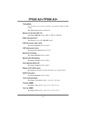
...5ns, 195ns, 327.5ns. CKE based power down mode The Choices: Disabled (default), Enabled. DDRII Timing Item The Choices: Disabled (default), Enabled. Memory Clock Value OR Limi The Choices: DDR 400 (default), DDR 533, DDR 667, DDR 800. DQS Training Control The Choices: Perform DQS, Skip ... of [31:24] IO space The Choices: C0 (default); Min=0000, Max=00FF, key in a HEX number. Memory Hole Remapping The Choices: Enabled (default), Disabled. TF520 A2+/TF560 A2+ Timing Mode This item allows you to choose to manually or automatically regulate the DDR T imin g. Auto Optimize Bottom IO...
...5ns, 195ns, 327.5ns. CKE based power down mode The Choices: Disabled (default), Enabled. DDRII Timing Item The Choices: Disabled (default), Enabled. Memory Clock Value OR Limi The Choices: DDR 400 (default), DDR 533, DDR 667, DDR 800. DQS Training Control The Choices: Perform DQS, Skip ... of [31:24] IO space The Choices: C0 (default); Min=0000, Max=00FF, key in a HEX number. Memory Hole Remapping The Choices: Enabled (default), Disabled. TF520 A2+/TF560 A2+ Timing Mode This item allows you to choose to manually or automatically regulate the DDR T imin g. Auto Optimize Bottom IO...


