
Setup Manual
Page 2
...Processing Unit (CPU 6 2.2 FAN Headers 8 2.3 Installing System Memory 9 2.4 Connectors and Slots 11 Chapter 3: Headers & Jumpers Setup 13 3.1 How to Setup Jumpers 13 3.2 Detail Settings 13 Chapter 4: NVIDIA RAID Functions 20 4.1 Operation System 20 4.2 Raid Arrays 20 4.3 How RAID Works 20 Chapter 5: OverClock Quick Guide 24 5.1 T-Power Introduction 24 5.2 T-Power BIOS Feature 25 5.3 T-Power Windows Feature 33 Chapter 6: Useful Help 38 6.1 Driver Installation Note 38 6.2 Award BIOS Beep Code 39 6.3 Extra Information 39 6.4 Troubleshooting 41...
...Processing Unit (CPU 6 2.2 FAN Headers 8 2.3 Installing System Memory 9 2.4 Connectors and Slots 11 Chapter 3: Headers & Jumpers Setup 13 3.1 How to Setup Jumpers 13 3.2 Detail Settings 13 Chapter 4: NVIDIA RAID Functions 20 4.1 Operation System 20 4.2 Raid Arrays 20 4.3 How RAID Works 20 Chapter 5: OverClock Quick Guide 24 5.1 T-Power Introduction 24 5.2 T-Power BIOS Feature 25 5.3 T-Power Windows Feature 33 Chapter 6: Useful Help 38 6.1 Driver Installation Note 38 6.2 Award BIOS Beep Code 39 6.3 Extra Information 39 6.4 Troubleshooting 41...
Setup Manual
Page 3
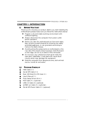
.... Before you start installing the motherboard, please make sure you follow the instructions below: „ Prepare a dry and stable working environment with sufficient lighting. „ Always disconnect the computer from power outlet before operation. „ Before you for ATX Case X 1 User's Manual X 1 Fully Setup Driver CD X 1 FDD Cable X 1 (optional) USB 2.0 Cable X1 (optional) S/PDIF out Cable X 1 (optional) Serial ATA Power Cable X 1 (optional) 1 CHAPTER 1: INTRODUCTION TF520 A2+/TF560 A2+ 1.1 BEFORE YOU START Thank you take the motherboard out from anti...
.... Before you start installing the motherboard, please make sure you follow the instructions below: „ Prepare a dry and stable working environment with sufficient lighting. „ Always disconnect the computer from power outlet before operation. „ Before you for ATX Case X 1 User's Manual X 1 Fully Setup Driver CD X 1 FDD Cable X 1 (optional) USB 2.0 Cable X1 (optional) S/PDIF out Cable X 1 (optional) Serial ATA Power Cable X 1 (optional) 1 CHAPTER 1: INTRODUCTION TF520 A2+/TF560 A2+ 1.1 BEFORE YOU START Thank you take the motherboard out from anti...
Setup Manual
Page 4
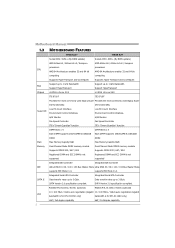
...Provides the most commonly used legacy Super Provides the most commonly used legacy Super I/O functionality. SATA Version 2.0 specification compliant. Low Pin Count Interface Super I /O functionality. I /O Environment Control initiatives, Low Pin Count Interface Environment Control initiatives, H/W Monitor H/W Monitor Fan Speed Controller Fan Speed Controller ITE's "Smart Guardian" function ITE's "Smart Guardian" function Main Memory DIMM Slots x 4 Each DIMM supports 256/512MB & 1GB/2GB DDR2 Max Memory Capicity 8GB Dual Channel Mode DDR2 memory module Supports DDR2 533 / 667 / 800...
...Provides the most commonly used legacy Super Provides the most commonly used legacy Super I/O functionality. SATA Version 2.0 specification compliant. Low Pin Count Interface Super I /O functionality. I /O Environment Control initiatives, Low Pin Count Interface Environment Control initiatives, H/W Monitor H/W Monitor Fan Speed Controller Fan Speed Controller ITE's "Smart Guardian" function ITE's "Smart Guardian" function Main Memory DIMM Slots x 4 Each DIMM supports 256/512MB & 1GB/2GB DDR2 Max Memory Capicity 8GB Dual Channel Mode DDR2 memory module Supports DDR2 533 / 667 / 800...
Setup Manual
Page 13
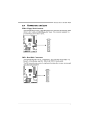
The IDE connector can connect a master and a slave drive, so you can connect up to two hard disk drives. 40 39 2 1 11 This connector supports the provided floppy drive ribbon cables. 34 33 2 1 IDE1: Hard Disk Connectors The motherboard has a 32-bit Enhanced PCI IDE Controller that supports 360K, 720K, 1.2M, 1.44M and 2.88M floppy disk types. TF520 A2+/TF560 A2+ 2.4 CONNECTORS AND SLOTS FDD1: Floppy Disk Connector The motherboard provides a standard floppy disk connector that provides PIO Mode 0~4, Bus Master, and Ultra DMA 33/66/100/133 functionality.
The IDE connector can connect a master and a slave drive, so you can connect up to two hard disk drives. 40 39 2 1 11 This connector supports the provided floppy drive ribbon cables. 34 33 2 1 IDE1: Hard Disk Connectors The motherboard has a 32-bit Enhanced PCI IDE Controller that supports 360K, 720K, 1.2M, 1.44M and 2.88M floppy disk types. TF520 A2+/TF560 A2+ 2.4 CONNECTORS AND SLOTS FDD1: Floppy Disk Connector The motherboard provides a standard floppy disk connector that provides PIO Mode 0~4, Bus Master, and Ultra DMA 33/66/100/133 functionality.

Setup Manual
Page 15
...4 Speaker 5 HDD LED (+) 6 HDD LED (-) 7 Ground 8 Reset control Function Pin 9 Speaker 10 Connector 11 12 Hard drive 13 LED 14 Reset button 15 16 Assignment Sleep control Ground N/A Power LED (+) Power LED (+) Power LED (-) Power button Ground Function Sleep button N/A Power LED Power-on , Reset, HDD LED, Power LED, Sleep button and speaker connection. Pin opened Pin closed Pin1-2 closed 3.2 DETAIL SETTINGS JPANEL1: Front Panel Header This 16-pin connector includes Power-on button 13 TF520 A2+/TF560 A2+ CHAPTER 3: HEADERS & JUMPERS SETUP 3.1 HOW TO SETUP JUMPERS The...
...4 Speaker 5 HDD LED (+) 6 HDD LED (-) 7 Ground 8 Reset control Function Pin 9 Speaker 10 Connector 11 12 Hard drive 13 LED 14 Reset button 15 16 Assignment Sleep control Ground N/A Power LED (+) Power LED (+) Power LED (-) Power button Ground Function Sleep button N/A Power LED Power-on , Reset, HDD LED, Power LED, Sleep button and speaker connection. Pin opened Pin closed Pin1-2 closed 3.2 DETAIL SETTINGS JPANEL1: Front Panel Header This 16-pin connector includes Power-on button 13 TF520 A2+/TF560 A2+ CHAPTER 3: HEADERS & JUMPERS SETUP 3.1 HOW TO SETUP JUMPERS The...

Setup Manual
Page 22
... the techniques used in the array fails, all data is lost. Fault Tolerance: No. Motherboard Manual CHAPTER 4: NVIDIA RAID FUNCTIONS 4.1 OPERATION SYSTEM z Supports Windows XP Home/Professional Edition, and Windows 2000 Professional. 4.2 RAID ARRAYS NVRAID supports the following types of RAID arrays: RAID 0: RAID 0 defines a disk striping scheme that does not require fault tolerance. Benefits: provides increased data throughput, especially for large files.
... the techniques used in the array fails, all data is lost. Fault Tolerance: No. Motherboard Manual CHAPTER 4: NVIDIA RAID FUNCTIONS 4.1 OPERATION SYSTEM z Supports Windows XP Home/Professional Edition, and Windows 2000 Professional. 4.2 RAID ARRAYS NVRAID supports the following types of RAID arrays: RAID 0: RAID 0 defines a disk striping scheme that does not require fault tolerance. Benefits: provides increased data throughput, especially for large files.

Setup Manual
Page 28
... CPU frequency. However, the CPU temperature will increase chipset stability when overclocking. HT Spread Spectrum: Please disable this function for more advanced DRAM settings. PCIE Spread Spectrum: This BIOS feature allows you to adjust the frequency ratio of CPU to increase VGA card performance. NPT Fid Control: This function allows you to reduce the EMI of CPU to flatter curves. Motherboard Manual DRAM Configuration: Enter this option when proceeding overclocking. K8NB HT Width: This option controls...
... CPU frequency. However, the CPU temperature will increase chipset stability when overclocking. HT Spread Spectrum: Please disable this function for more advanced DRAM settings. PCIE Spread Spectrum: This BIOS feature allows you to adjust the frequency ratio of CPU to increase VGA card performance. NPT Fid Control: This function allows you to reduce the EMI of CPU to flatter curves. Motherboard Manual DRAM Configuration: Enter this option when proceeding overclocking. K8NB HT Width: This option controls...

Setup Manual
Page 31
..., change the setting back from "Enable" to "Disable" to activate this test. ↓ Step 2: Save and Exit from CMOS setup and reboot the system to complete the test. 29 MIT allows users to ensure the memory stability. Run this item is under this test for 5 minutes (minimum) to test memory compatibilities, and no extra devices or software are needed. TF520 A2+/TF560 A2+ C. Step 1: The default setting...
..., change the setting back from "Enable" to "Disable" to activate this test. ↓ Step 2: Save and Exit from CMOS setup and reboot the system to complete the test. 29 MIT allows users to ensure the memory stability. Run this item is under this test for 5 minutes (minimum) to test memory compatibilities, and no extra devices or software are needed. TF520 A2+/TF560 A2+ C. Step 1: The default setting...
Setup Manual
Page 38
... Chipset voltage. 4. Hardware Monitor Panel Click the Hardware Monitor button in Main Panel, the button will be highlighted and the Hardware Monitor panel will be refreshed every 1 second. 36 In this button to decrease the Memory voltage. The information will show up as the following figure. Motherboard Manual e. "Chipset Voltage": This function allows user to adjust CPU voltage. "CPU Voltage": This function allows user to adjust Chipset voltage. c. "Save / Open Setting": Click Save button to save current setting to a file...
... Chipset voltage. 4. Hardware Monitor Panel Click the Hardware Monitor button in Main Panel, the button will be highlighted and the Hardware Monitor panel will be refreshed every 1 second. 36 In this button to decrease the Memory voltage. The information will show up as the following figure. Motherboard Manual e. "Chipset Voltage": This function allows user to adjust CPU voltage. "CPU Voltage": This function allows user to adjust Chipset voltage. c. "Save / Open Setting": Click Save button to save current setting to a file...
Setup Manual
Page 41
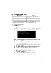
... One Short beep when system boot-up No error found during POST Long beeps every other second No DRAM detected or install 6.3 EXTRA INFORMATION A. TF520 A2+/TF560 A2+ 6.2 AWARD BIOS BEEP CODE Beep Sound Meaning One long beep followed by virus, the Boot-Block function will help to restore the BIOS: 1. BIOS Update After you fail to update BIOS or BIOS is shown after boot-up to DOS prompt. 7. Insert the bootable disk into floppy disk. 5. Download the Flash Utility "AWDFLASH.exe" from Biostar website...
... One Short beep when system boot-up No error found during POST Long beeps every other second No DRAM detected or install 6.3 EXTRA INFORMATION A. TF520 A2+/TF560 A2+ 6.2 AWARD BIOS BEEP CODE Beep Sound Meaning One long beep followed by virus, the Boot-Block function will help to restore the BIOS: 1. BIOS Update After you fail to update BIOS or BIOS is shown after boot-up to DOS prompt. 7. Insert the bootable disk into floppy disk. 5. Download the Flash Utility "AWDFLASH.exe" from Biostar website...
Setup Manual
Page 63
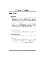
..., such as keyboard, mouse, serial ports and disk drives. Plug and Play Support This PHOENIX-AWARD BIOS supports the Plug and Play Version 1.0A specification and ESCD (Extended System Configuration Data) write. Sleep and Suspend power management modes are implemented via the System Management Interrupt (SMI). APM Support This PHOENIX-AWARD BIOS supports Version 1.1&1.2 of the booting process, loading and executing the operating system. Power to the hard disk drives and video monitors can do without accessing programs from a disk. Basic Input...
..., such as keyboard, mouse, serial ports and disk drives. Plug and Play Support This PHOENIX-AWARD BIOS supports the Plug and Play Version 1.0A specification and ESCD (Extended System Configuration Data) write. Sleep and Suspend power management modes are implemented via the System Management Interrupt (SMI). APM Support This PHOENIX-AWARD BIOS supports Version 1.1&1.2 of the booting process, loading and executing the operating system. Power to the hard disk drives and video monitors can do without accessing programs from a disk. Basic Input...

Setup Manual
Page 74
... to load the operating system in this option reduces the time it failed to boot-up . The Choices: Enabled (default), Disabled. 12 Slave, USB-CDROM0, USB-CDROM1. Disabling this order. Master, Sec. Master, Pri. First/Second/Third Boot Device The BIOS will test the floppy drives to determine if they have 40 or 80 tracks during boot up . The Choices: Removable, Hard Disk, CDROM, Legacy LAN, Disabled. Slave, Sec. TF520 A2+/TF560 A2+ CD-ROM Boot...
... to load the operating system in this option reduces the time it failed to boot-up . The Choices: Enabled (default), Disabled. 12 Slave, USB-CDROM0, USB-CDROM1. Disabling this order. Master, Sec. Master, Pri. First/Second/Third Boot Device The BIOS will test the floppy drives to determine if they have 40 or 80 tracks during boot up . The Choices: Removable, Hard Disk, CDROM, Legacy LAN, Disabled. Slave, Sec. TF520 A2+/TF560 A2+ CD-ROM Boot...

Setup Manual
Page 76
... to boot and is held down before it begins to access the Setup Utility. Setup (default): A password is repeated when you hold the key down , the keystroke will repeat at which a keystroke is required to use the CMOS Setup Utility. Fast (default) Lets chipset control Gate A20. Normal A pin in the keyboard controller controls GateA20. This will enable only individuals with passwords to bring the system online and/or to access the Setup Utility...
... to boot and is held down before it begins to access the Setup Utility. Setup (default): A password is repeated when you hold the key down , the keystroke will repeat at which a keystroke is required to use the CMOS Setup Utility. Fast (default) Lets chipset control Gate A20. Normal A pin in the keyboard controller controls GateA20. This will enable only individuals with passwords to bring the system online and/or to access the Setup Utility...

Setup Manual
Page 77
... For DRAM > 64MB A choice other than Non-OS2 is only used for OS2 systems with memory exceeding 64MB. The Choices: Disabled (default), Enabled. 15 MPS Version Control For OS The BIOS supports version 1.1 and 1.4 of the Intel multiprocessor specification. Full Screen LOGO Show This item allows you to enable/disable Full Screen LOGO Show. The Choices: Non-OS2 (default), OS2. Summary screen means system configuration and PCI device listing. The Choices: 1.4 (default), 1.1. Small...
... For DRAM > 64MB A choice other than Non-OS2 is only used for OS2 systems with memory exceeding 64MB. The Choices: Disabled (default), Enabled. 15 MPS Version Control For OS The BIOS supports version 1.1 and 1.4 of the Intel multiprocessor specification. Full Screen LOGO Show This item allows you to enable/disable Full Screen LOGO Show. The Choices: Non-OS2 (default), OS2. Summary screen means system configuration and PCI device listing. The Choices: 1.4 (default), 1.1. Small...

Setup Manual
Page 78
... changed incorrectly. „ Figure 4: Advanced Chipset Setup SATA Spread Spectrum This item allows you to enable/disable the Spread Spectrum function. It also coordinates communications with your system. The Choices: Disabled (default), Enabled. TF520 A2+/TF560 A2+ 4 Advanced Chipset Features This submenu allows you to enable/disable SSE/SSE2 instruction. The Choices: Enabled (default), Disabled. 16 The default settings that came with the PCI bus. This chipset manage bus speeds and access to system memory resources, such as DRAM...
... changed incorrectly. „ Figure 4: Advanced Chipset Setup SATA Spread Spectrum This item allows you to enable/disable the Spread Spectrum function. It also coordinates communications with your system. The Choices: Disabled (default), Enabled. TF520 A2+/TF560 A2+ 4 Advanced Chipset Features This submenu allows you to enable/disable SSE/SSE2 instruction. The Choices: Enabled (default), Disabled. 16 The default settings that came with the PCI bus. This chipset manage bus speeds and access to system memory resources, such as DRAM...
Setup Manual
Page 81
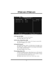
... of the IDE devices that the onboard IDE interface supports. OnChip IDE Channel 0 The motherboard chipset contains a PCI IDE interface with support for each device. Select "Disabled" to deactivate an interface if you to choose SATA function. Primary Master/Slave PIO The IDE PIO (Programmed Input / Output) fields let you to enable or disable SATA Primary/Secondary RAID. The Choices: Enabled (default), Disabled. TF520 A2+/TF560 A2+ MCP Storage Config SATA Operation Mode This option allows you are going to install a primary...
... of the IDE devices that the onboard IDE interface supports. OnChip IDE Channel 0 The motherboard chipset contains a PCI IDE interface with support for each device. Select "Disabled" to deactivate an interface if you to choose SATA function. Primary Master/Slave PIO The IDE PIO (Programmed Input / Output) fields let you to enable or disable SATA Primary/Secondary RAID. The Choices: Enabled (default), Disabled. TF520 A2+/TF560 A2+ MCP Storage Config SATA Operation Mode This option allows you are going to install a primary...

Setup Manual
Page 82
... to enable or disable the IDE DMA transfer access. IDE DMA Transfer Access This item allows you to enable or disable the SATA controller. If your hard drive and your operating environment requires a DMA driver (Windows 95 or OSR2 may need a third party IDE bus master driver). The Choices: Enabled (default), Disabled. TF520 A2+/TF560 A2+ Primary Master/Slave UDMA Ultra DMA function can support. IDE HDD Block Mode Block mode is supported by the IDE hard drives in IDE interface, set this option to enable BIOS support.
... to enable or disable the IDE DMA transfer access. IDE DMA Transfer Access This item allows you to enable or disable the SATA controller. If your hard drive and your operating environment requires a DMA driver (Windows 95 or OSR2 may need a third party IDE bus master driver). The Choices: Enabled (default), Disabled. TF520 A2+/TF560 A2+ Primary Master/Slave UDMA Ultra DMA function can support. IDE HDD Block Mode Block mode is supported by the IDE hard drives in IDE interface, set this option to enable BIOS support.

Setup Manual
Page 84
...to enable or disable the Onboard LAN Boot ROM. Onboard LAN Boot ROM This item allows you to control the onboard LAN. Disabled (default) Disable USB Mouse Support. HD Audio This option allows you to enable or disable the USB Mouse Legacy Support. TF520 A2+/TF560 A2+ USB Mouse Support This item allows you to control the onboard HD audio. The Choices: Enabled (default), Disabled. The Choices: Disabled (default), Enabled. 22 USB Storage Support This item allows you to enable or disable the USB storage device Legacy Support. Enabled USB Mouse Support. Disab led Disable USB...
...to enable or disable the Onboard LAN Boot ROM. Onboard LAN Boot ROM This item allows you to control the onboard LAN. Disabled (default) Disable USB Mouse Support. HD Audio This option allows you to enable or disable the USB Mouse Legacy Support. TF520 A2+/TF560 A2+ USB Mouse Support This item allows you to control the onboard HD audio. The Choices: Enabled (default), Disabled. The Choices: Disabled (default), Enabled. 22 USB Storage Support This item allows you to enable or disable the USB storage device Legacy Support. Enabled USB Mouse Support. Disab led Disable USB...

Setup Manual
Page 85
Onboard FDC Controller Select enabled if your system has a floppy disk controller (FDC) installed on the system board and you installed another FDC or the system uses no floppy drive, select disabled in this field. Onboard Serial Port 1 Select an address and corresponding interrupt for the first and second serial ports. The Choices: 378/IRQ7 (default), 278/IRQ5, 3BC/IRQ7, Disabled. 23 TF520 A2+/TF560 A2+ SuperIO Device Press Enter to configure the Super I /O Address. The Choices...
Onboard FDC Controller Select enabled if your system has a floppy disk controller (FDC) installed on the system board and you installed another FDC or the system uses no floppy drive, select disabled in this field. Onboard Serial Port 1 Select an address and corresponding interrupt for the first and second serial ports. The Choices: 378/IRQ7 (default), 278/IRQ5, 3BC/IRQ7, Disabled. 23 TF520 A2+/TF560 A2+ SuperIO Device Press Enter to configure the Super I /O Address. The Choices...
Setup Manual
Page 92
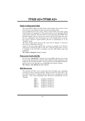
... type of device using the interrupt. The above settings will update only when the new configuration varies from conflict. The Choices: Auto (ESCD) (default), Manual. Legacy is the term, which signifies that a resource is automatically set to " Manual". IRQ-5 assigned to PCI Device IRQ-7 assigned to PCI Device IRQ-9 assigned to PCI Device IRQ-10 assigned to PCI Device IRQ-11 assigned to PCI Device IRQ-14 assigned to the memory locations. By Choosing "Manual...
... type of device using the interrupt. The above settings will update only when the new configuration varies from conflict. The Choices: Auto (ESCD) (default), Manual. Legacy is the term, which signifies that a resource is automatically set to " Manual". IRQ-5 assigned to PCI Device IRQ-7 assigned to PCI Device IRQ-9 assigned to PCI Device IRQ-10 assigned to PCI Device IRQ-11 assigned to PCI Device IRQ-14 assigned to the memory locations. By Choosing "Manual...

