
Setup Manual
Page 2
Table of Contents Chapter 1: Introduction 1 1.1 Before You Start 1 1.2 Package Checklist 1 1.3 Motherboard Features 2 1.4 Rear Panel Connectors (Ver 5.x 4 1.5 Rear Panel Connectors (Ver 6.x 4 1.6 Motherboard Layout 5 Chapter 2: Hardware Installation 6 2.1 Installing Central Processing Unit (CPU 6 2.2 FAN Headers 8 2.3 Installing System Memory 9 2.4 Connectors and Slots 11 Chapter 3: Headers & Jumpers Setup 13 3.1 How to ...
Table of Contents Chapter 1: Introduction 1 1.1 Before You Start 1 1.2 Package Checklist 1 1.3 Motherboard Features 2 1.4 Rear Panel Connectors (Ver 5.x 4 1.5 Rear Panel Connectors (Ver 6.x 4 1.6 Motherboard Layout 5 Chapter 2: Hardware Installation 6 2.1 Installing Central Processing Unit (CPU 6 2.2 FAN Headers 8 2.3 Installing System Memory 9 2.4 Connectors and Slots 11 Chapter 3: Headers & Jumpers Setup 13 3.1 How to ...
Setup Manual
Page 3
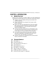
...grounded wrist strap to remove the static charge. „ Avoid touching the components on motherboard or the rear side of the board unless necessary. Before you start installing the motherboard, please make sure you follow the instructions below: „ Prepare a dry and ...1.2 PACKAGE CHECKLIST HDD Cable X 1 Serial ATA Cable X 2 Rear I/O Panel for choosing our product. CHAPTER 1: INTRODUCTION TF520 A2+/TF560 A2+ 1.1 BEFORE YOU START Thank you take the motherboard out from anti-static bag, ground yourself properly by touching any unfastened small parts inside the case after installation.
...grounded wrist strap to remove the static charge. „ Avoid touching the components on motherboard or the rear side of the board unless necessary. Before you start installing the motherboard, please make sure you follow the instructions below: „ Prepare a dry and ...1.2 PACKAGE CHECKLIST HDD Cable X 1 Serial ATA Cable X 2 Rear I/O Panel for choosing our product. CHAPTER 1: INTRODUCTION TF520 A2+/TF560 A2+ 1.1 BEFORE YOU START Thank you take the motherboard out from anti-static bag, ground yourself properly by touching any unfastened small parts inside the case after installation.
Setup Manual
Page 4
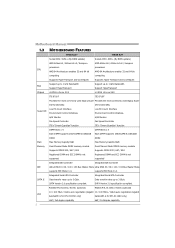
... the most commonly used legacy Super I/O functionality. supports PIO Mode 0~4. SATA Version 2.0 specification compliant. Low Pin Count Interface Super I /O functionality. SATA Version 2.0 specification compliant. Motherboard Manual 1.3 MOTHERBOARD FEATURES TF520 A2+ TF560 A2+ Socket AM2 / AM2+ (By BIOS update) Socket AM2 / AM2+ (By BIOS update) AMD Athlon 64 / Athlon 64 x2 / Sempron AMD Athlon 64 / Athlon...
... the most commonly used legacy Super I/O functionality. supports PIO Mode 0~4. SATA Version 2.0 specification compliant. Low Pin Count Interface Super I /O functionality. SATA Version 2.0 specification compliant. Motherboard Manual 1.3 MOTHERBOARD FEATURES TF520 A2+ TF560 A2+ Socket AM2 / AM2+ (By BIOS update) Socket AM2 / AM2+ (By BIOS update) AMD Athlon 64 / Athlon 64 x2 / Sempron AMD Athlon 64 / Athlon...
Setup Manual
Page 6
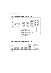
Motherboard Manual 1.4 REAR PANEL CONNECTORS (VER 5.X) PS/2 Mouse LAN PS/2 Keyboard COM1 USBX2 USBX2 USBX2 Center Rear Side Line In Line Out Mic In 1.5 REAR PANEL CONNECTORS (VER 6.X) PS/2 Mouse LA N PS/ 2 Keyboard COM1 USBX2 USBX2 USBX2 Line In/ Surround Line Out Mic I n 1/ Bass/ Center 4
Motherboard Manual 1.4 REAR PANEL CONNECTORS (VER 5.X) PS/2 Mouse LAN PS/2 Keyboard COM1 USBX2 USBX2 USBX2 Center Rear Side Line In Line Out Mic In 1.5 REAR PANEL CONNECTORS (VER 6.X) PS/2 Mouse LA N PS/ 2 Keyboard COM1 USBX2 USBX2 USBX2 Line In/ Surround Line Out Mic I n 1/ Bass/ Center 4
Setup Manual
Page 7
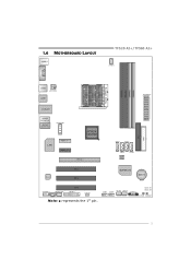
1.6 MOTHERBOARD LAYOUT JKBMS1 TF520 A2+/TF560 A2+ JCFAN1 JCOM1 JUSB2 JATXPWR2 JUSB1 DIMMA1 DIMMB1 DIMMA2 DIMMB2 J ATXPWR1 JUSBLAN1 IDE1 FDD1 AUDIO2 (for Ver 5.x) JAUDIO1 (for Ver 6.x) JATXPWR3 LAN PEX1_1 PEX1_2 nForce 520/560 PEX16_1 SATA1 SATA3 SATA2 BIOS SATA4 Codec PCI1 PCI2 SUPER I/O BAT1 PCI3 JAUDIOF1 JSPDIF_OUT JPRNT1 JCMOS1 JCDIN1 Note: ■ represents the 1st pin. JUSB3 JUSB4 JSFAN1 JSFAN2 JPANEL 1 LED_D1 LED_D2 RSTSW1 PWRSW1 5
1.6 MOTHERBOARD LAYOUT JKBMS1 TF520 A2+/TF560 A2+ JCFAN1 JCOM1 JUSB2 JATXPWR2 JUSB1 DIMMA1 DIMMB1 DIMMA2 DIMMB2 J ATXPWR1 JUSBLAN1 IDE1 FDD1 AUDIO2 (for Ver 5.x) JAUDIO1 (for Ver 6.x) JATXPWR3 LAN PEX1_1 PEX1_2 nForce 520/560 PEX16_1 SATA1 SATA3 SATA2 BIOS SATA4 Codec PCI1 PCI2 SUPER I/O BAT1 PCI3 JAUDIOF1 JSPDIF_OUT JPRNT1 JCMOS1 JCDIN1 Note: ■ represents the 1st pin. JUSB3 JUSB4 JSFAN1 JSFAN2 JPANEL 1 LED_D1 LED_D2 RSTSW1 PWRSW1 5

Setup Manual
Page 8
Motherboard Manual CHAPTER 2: HARDWARE INSTALLATION 2.1 INSTALLING CENTRAL PROCESSING UNIT (CPU) Step 1: Remove the socket protection cap. Step 3: Look for the white triangle on socket, and the gold triangle on CPU should point forwards this white triangle. The CPU will fit only in the correct orientation. 6 Step 2: Pull the lever toward direction A from the socket and then raise the lever up to a 90-degree angle.
Motherboard Manual CHAPTER 2: HARDWARE INSTALLATION 2.1 INSTALLING CENTRAL PROCESSING UNIT (CPU) Step 1: Remove the socket protection cap. Step 3: Look for the white triangle on socket, and the gold triangle on CPU should point forwards this white triangle. The CPU will fit only in the correct orientation. 6 Step 2: Pull the lever toward direction A from the socket and then raise the lever up to a 90-degree angle.

Setup Manual
Page 10
... Fan Headers JSFAN1 JSFAN2 Pin Assignment 1 Ground 2 +12V 3 FAN RPM rate sense 13 Note: The JCFAN1, JSFAN1, and JSFAN2 support 4-pin and 3-pin head connector. Motherboard Manual 2.2 FAN HEADERS These fan headers support cooling-fans built in the computer.
... Fan Headers JSFAN1 JSFAN2 Pin Assignment 1 Ground 2 +12V 3 FAN RPM rate sense 13 Note: The JCFAN1, JSFAN1, and JSFAN2 support 4-pin and 3-pin head connector. Motherboard Manual 2.2 FAN HEADERS These fan headers support cooling-fans built in the computer.

Setup Manual
Page 12
Dual Channel Memory installation To trigger the Dual Channel function of the same density in pairs, shown in the following table. Duual Channel Status DIMMA1 DIMMB1 DIMMA2 DIMMB2 Enabled O O X X Enabled X X O O Enabled O O O O (O means memory installed, X means memory not installed.) The DRAM bus width of the memory module must meet the following requirements: Install memory module of the motherboard, the memory module must be the same (x8 or x16) 10 Motherboard Manual C.
Dual Channel Memory installation To trigger the Dual Channel function of the same density in pairs, shown in the following table. Duual Channel Status DIMMA1 DIMMB1 DIMMA2 DIMMB2 Enabled O O X X Enabled X X O O Enabled O O O O (O means memory installed, X means memory not installed.) The DRAM bus width of the memory module must meet the following requirements: Install memory module of the motherboard, the memory module must be the same (x8 or x16) 10 Motherboard Manual C.
Setup Manual
Page 13
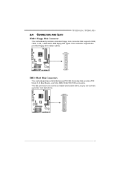
The IDE connector can connect a master and a slave drive, so you can connect up to two hard disk drives. 40 39 2 1 11 TF520 A2+/TF560 A2+ 2.4 CONNECTORS AND SLOTS FDD1: Floppy Disk Connector The motherboard provides a standard floppy disk connector that provides PIO Mode 0~4, Bus Master, and Ultra DMA 33/66/100/133 functionality. This connector supports the provided floppy drive ribbon cables. 34 33 2 1 IDE1: Hard Disk Connectors The motherboard has a 32-bit Enhanced PCI IDE Controller that supports 360K, 720K, 1.2M, 1.44M and 2.88M floppy disk types.
The IDE connector can connect a master and a slave drive, so you can connect up to two hard disk drives. 40 39 2 1 11 TF520 A2+/TF560 A2+ 2.4 CONNECTORS AND SLOTS FDD1: Floppy Disk Connector The motherboard provides a standard floppy disk connector that provides PIO Mode 0~4, Bus Master, and Ultra DMA 33/66/100/133 functionality. This connector supports the provided floppy drive ribbon cables. 34 33 2 1 IDE1: Hard Disk Connectors The motherboard has a 32-bit Enhanced PCI IDE Controller that supports 360K, 720K, 1.2M, 1.44M and 2.88M floppy disk types.

Setup Manual
Page 14
... bandwidth of 4GB/s simultaneously per direction; 500MB/s in total. - PEX1_1/PEX1_2: PCI-Express x1 Slots - PEX1_1 PEX1_2 PEX16_1 PCI1~PCI3: Peripheral Component Interconnect Slots This motherboard is designated as 32 bits. PCI1 PCI2 PCI3 12 This PCI slot is equipped with 3 standard PCI slots. PCI stands for Peripheral Component Interconnect, and...
... bandwidth of 4GB/s simultaneously per direction; 500MB/s in total. - PEX1_1/PEX1_2: PCI-Express x1 Slots - PEX1_1 PEX1_2 PEX16_1 PCI1~PCI3: Peripheral Component Interconnect Slots This motherboard is designated as 32 bits. PCI1 PCI2 PCI3 12 This PCI slot is equipped with 3 standard PCI slots. PCI stands for Peripheral Component Interconnect, and...

Setup Manual
Page 16
Motherboard Manual JATXPWR1: ATX Power Source Connector This connector allows user to CPU power circuit. 32 4 1 Pin Assignment 1 +12V 2 +12V 3 Ground 4 Ground 14 Pin Assignment 1 +3.3V 2 +3.3V 3 Ground 4 +5V 5 Ground 6 +5V 12 24 7 Ground 8 PW_OK 9 Standby Voltage +5V 10 +12V 11 +12V 12 +3.3V 13 +3.3V 14 -12V 15 Ground 16 PS-ON 1 13 17 Ground 18 Ground 19 Ground 20 NC 21 +5V 22 +5V 23 +5V 24 Ground JATXPWR2: ATX Power Source Connector By connecting this connector, it will provide +12V to connect 24-pin power connector on the ATX power supply.
Motherboard Manual JATXPWR1: ATX Power Source Connector This connector allows user to CPU power circuit. 32 4 1 Pin Assignment 1 +12V 2 +12V 3 Ground 4 Ground 14 Pin Assignment 1 +3.3V 2 +3.3V 3 Ground 4 +5V 5 Ground 6 +5V 12 24 7 Ground 8 PW_OK 9 Standby Voltage +5V 10 +12V 11 +12V 12 +3.3V 13 +3.3V 14 -12V 15 Ground 16 PS-ON 1 13 17 Ground 18 Ground 19 Ground 20 NC 21 +5V 22 +5V 23 +5V 24 Ground JATXPWR2: ATX Power Source Connector By connecting this connector, it will provide +12V to connect 24-pin power connector on the ATX power supply.

Setup Manual
Page 18
... seconds. 4. Reset your desired password or clear the CMOS data. 16 Set the jumper to "Pin 1-2 close ". 3. Motherboard Manual SATA1~SATA4: Serial ATA Connectors The motherboard has a PCI to SATA Controller with 4 channels SATA interface, it allows user to restore the BIOS safe setting and the ...CMOS data, please carefully follow the procedures to avoid damaging the motherboard. 13 Pin 1-2 Close: Normal Operation (default). 13 13 Pin 2-3 Close: Clear CMOS data. ※ Clear CMOS Procedures: 1. Remove AC ...
... seconds. 4. Reset your desired password or clear the CMOS data. 16 Set the jumper to "Pin 1-2 close ". 3. Motherboard Manual SATA1~SATA4: Serial ATA Connectors The motherboard has a PCI to SATA Controller with 4 channels SATA interface, it allows user to restore the BIOS safe setting and the ...CMOS data, please carefully follow the procedures to avoid damaging the motherboard. 13 Pin 1-2 Close: Normal Operation (default). 13 13 Pin 2-3 Close: Clear CMOS data. ※ Clear CMOS Procedures: 1. Remove AC ...

Setup Manual
Page 20
LED_D1 LED_D2 LED_D1 and LED_D2: These 2 LED indicate system power on the motherboard to the table below for different messages: LED_D1 LED_D2 Message ON ON OFF OFF ON Normal OFF Memory Error ON VGA Error OFF Abnormal: CPU / ... to show system status. Pin Assignment 1 1 +12V 2 Ground 3 Ground 4 VCC 4 On-Board LED Indicators There are 2 LED indicators on diagnostics. Exclusive power for graphics cards. Motherboard Manual JATXPWR3: Auxiliary Power for Graphics This connector is an auxiliary power connection for the graphics card provides better graphics performance.
LED_D1 LED_D2 LED_D1 and LED_D2: These 2 LED indicate system power on the motherboard to the table below for different messages: LED_D1 LED_D2 Message ON ON OFF OFF ON Normal OFF Memory Error ON VGA Error OFF Abnormal: CPU / ... to show system status. Pin Assignment 1 1 +12V 2 Ground 3 Ground 4 VCC 4 On-Board LED Indicators There are 2 LED indicators on diagnostics. Exclusive power for graphics cards. Motherboard Manual JATXPWR3: Auxiliary Power for Graphics This connector is an auxiliary power connection for the graphics card provides better graphics performance.

Setup Manual
Page 22
.... Depending on the system environment. If any environment that improves disk read and write times for many applications. Block 1 Block 3 Block 5 20 Block 2 Block 4 Block 6 Motherboard Manual CHAPTER 4: NVIDIA RAID FUNCTIONS 4.1 OPERATION SYSTEM z Supports Windows XP Home/Professional Edition, and Windows 2000 Professional. 4.2 RAID ARRAYS NVRAID supports the following types of...
.... Depending on the system environment. If any environment that improves disk read and write times for many applications. Block 1 Block 3 Block 5 20 Block 2 Block 4 Block 6 Motherboard Manual CHAPTER 4: NVIDIA RAID FUNCTIONS 4.1 OPERATION SYSTEM z Supports Windows XP Home/Professional Edition, and Windows 2000 Professional. 4.2 RAID ARRAYS NVRAID supports the following types of...

Setup Manual
Page 24
... Benefits Drives: Minimum 4, and maximum is 6 or 8, depending on the platform. Benefits: Optimizes for both fault tolerance and performance, allowing for automatic redundancy. Motherboard Manual RAID 0+1: RAID 0 drives can be simultaneously used with other RAID levels in a RAID 0+1 solution for data redundancy, the same as RAID level 1. Fault...
... Benefits Drives: Minimum 4, and maximum is 6 or 8, depending on the platform. Benefits: Optimizes for both fault tolerance and performance, allowing for automatic redundancy. Motherboard Manual RAID 0+1: RAID 0 drives can be simultaneously used with other RAID levels in a RAID 0+1 solution for data redundancy, the same as RAID level 1. Fault...

Setup Manual
Page 26
...better system performance, the BIOS firmware is designed for your reference only and the actual BIOS information and settings on many precise tests, Biostar Engineering Team (BET) has developed this manual. For further information of setting up the BIOS, please refer to the BIOS Manual ...in this manual is able to present the best system state according to raise system performance. Motherboard Manual CHAPTER 5: OVERCLOCK QUICK GUIDE 5.1 T-POWER INTRODUCTION Biostar T-Power is a whole new utility that is being continuously updated. Based on board may be different from this...
...better system performance, the BIOS firmware is designed for your reference only and the actual BIOS information and settings on many precise tests, Biostar Engineering Team (BET) has developed this manual. For further information of setting up the BIOS, please refer to the BIOS Manual ...in this manual is able to present the best system state according to raise system performance. Motherboard Manual CHAPTER 5: OVERCLOCK QUICK GUIDE 5.1 T-POWER INTRODUCTION Biostar T-Power is a whole new utility that is being continuously updated. Based on board may be different from this...

Setup Manual
Page 28
HT Spread Spectrum: Please disable this function for more advanced DRAM settings. NPT Fid Control: This function allows you to reduce the EMI of CPU. Motherboard Manual DRAM Configuration: Enter this option when proceeding overclocking. Please disable this option when proceeding overclocking. K8NB HT Width: This option controls the HyperTransport width ...
HT Spread Spectrum: Please disable this function for more advanced DRAM settings. NPT Fid Control: This function allows you to reduce the EMI of CPU. Motherboard Manual DRAM Configuration: Enter this option when proceeding overclocking. Please disable this option when proceeding overclocking. K8NB HT Width: This option controls the HyperTransport width ...

Setup Manual
Page 30
... performance. Notices: 1. There are able to personal preference. 28 CMOS Reloading Program (C.R.P.): It allows users to reload any saved CMOS setting for customizing system configurations. Motherboard Manual V12 Tech Engine: This setting will be based on the selected CPU model. Not all types of AMD CPU perform above overclock setting ideally;
... performance. Notices: 1. There are able to personal preference. 28 CMOS Reloading Program (C.R.P.): It allows users to reload any saved CMOS setting for customizing system configurations. Motherboard Manual V12 Tech Engine: This setting will be based on the selected CPU model. Not all types of AMD CPU perform above overclock setting ideally;

Setup Manual
Page 32
Motherboard Manual D. When the system hangs up . E. Step 2: Insert the floppy disk and reboot the system to get into a floppy disk. Step 3: Select the item "Integrated ... always on whenever the system starts up , S.R.S. However, it can prevent system hang-up due to download the latest BIOS file. Step 1: Go to Biostar website (http://www.biostar.com.tw) to inappropriate overclock actions. Step 5: When the BIOS update is a safe and quick way to upgrade BIOS. Self Recovery System (S.R.S.): This...
Motherboard Manual D. When the system hangs up . E. Step 2: Insert the floppy disk and reboot the system to get into a floppy disk. Step 3: Select the item "Integrated ... always on whenever the system starts up , S.R.S. However, it can prevent system hang-up due to download the latest BIOS file. Step 1: Go to Biostar website (http://www.biostar.com.tw) to inappropriate overclock actions. Step 5: When the BIOS update is a safe and quick way to upgrade BIOS. Self Recovery System (S.R.S.): This...

Setup Manual
Page 34
CPU Fan Full speed When CPU temperature arrives to the set value. The range is from 0℃~127℃, with an interval of 1℃. Start PWM Value When CPU temperature arrives to the set value, the CPU fan will work when CPU temperature arrives to this set value, the CPU fan will work under Smart Fan Function mode. The range is from 0℃~127℃, with an interval of 1℃. Motherboard Manual CPU Fan Start The CPU fan starts to work under Full Speed. The range is from 0~127, with an interval of 1. 32
CPU Fan Full speed When CPU temperature arrives to the set value. The range is from 0℃~127℃, with an interval of 1℃. Start PWM Value When CPU temperature arrives to the set value, the CPU fan will work when CPU temperature arrives to this set value, the CPU fan will work under Smart Fan Function mode. The range is from 0℃~127℃, with an interval of 1℃. Motherboard Manual CPU Fan Start The CPU fan starts to work under Full Speed. The range is from 0~127, with an interval of 1. 32


