Setup Manual
Page 2
Table of Contents Chapter 1: Introduction 1 1.1 Before You Start 1 1.2 Package Checklist 1 1.3 Motherboard Features 2 1.4 Rear Panel Connectors 3 1.5 Motherboard Layout 4 Chapter 2: Hardware Installation 5 2.1 Installing Central Processing Unit (CPU 5 2.2 FAN Headers 7 2.3 Installing System Memory 8 2.4 Connectors and Slots 10 Chapter 3: Headers & Jumpers Setup 12 3.1 How to ...
Table of Contents Chapter 1: Introduction 1 1.1 Before You Start 1 1.2 Package Checklist 1 1.3 Motherboard Features 2 1.4 Rear Panel Connectors 3 1.5 Motherboard Layout 4 Chapter 2: Hardware Installation 5 2.1 Installing Central Processing Unit (CPU 5 2.2 FAN Headers 7 2.3 Installing System Memory 8 2.4 Connectors and Slots 10 Chapter 3: Headers & Jumpers Setup 12 3.1 How to ...
Setup Manual
Page 3
Loose parts will cause short circuits which may be differed by area or your motherboard version. 1 Before you start installing the motherboard, please make sure you follow the instructions below: „ Prepare a dry and stable working environment with sufficient lighting. „...not try to remove the static charge. „ Avoid touching the components on motherboard or the rear side of the board unless necessary. CHAPTER 1: INTRODUCTION G31D-M7 1.1 BEFORE YOU START Thank you take the motherboard out from anti-static bag, ground yourself properly by touching any safely grounded ...
Loose parts will cause short circuits which may be differed by area or your motherboard version. 1 Before you start installing the motherboard, please make sure you follow the instructions below: „ Prepare a dry and stable working environment with sufficient lighting. „...not try to remove the static charge. „ Avoid touching the components on motherboard or the rear side of the board unless necessary. CHAPTER 1: INTRODUCTION G31D-M7 1.1 BEFORE YOU START Thank you take the motherboard out from anti-static bag, ground yourself properly by touching any safely grounded ...
Setup Manual
Page 4
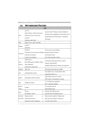
... connector Connector Printer Port Connector Serial port Connector (Optional) x1 Each connector supports 2 Floppy drives x1 Each connector supports 1 Printer port x1 Connects to 3.0 Gb/s. Motherboard Manual 1.3 MOTHERBOARD FEATURES SPEC LGA 775 Supports Hyper-Threading / Execute Disable Bit / Intel Core2Duo / Pentium Dual-Core / Enhanced Intel SpeedStep® / Intel Architecture-64 / CPU Celeron...
... connector Connector Printer Port Connector Serial port Connector (Optional) x1 Each connector supports 2 Floppy drives x1 Each connector supports 1 Printer port x1 Connects to 3.0 Gb/s. Motherboard Manual 1.3 MOTHERBOARD FEATURES SPEC LGA 775 Supports Hyper-Threading / Execute Disable Bit / Intel Core2Duo / Pentium Dual-Core / Enhanced Intel SpeedStep® / Intel Architecture-64 / CPU Celeron...
Setup Manual
Page 6
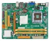
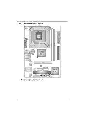
Motherboard Manual 1.5 MOTHERBOARD LAYOUT JKBMS1 LGA775 CPU1 JCFAN1 J ATXPWR 1 J ATX PWR 2 JVGA 1 DDR2_ A 1 DDR2_ B 1 JUSB V1 IDE 1 JUSB2 BAT1 JRJ45USB1 Intel G31 JAUDIO1 JAUDIOF1 LAN Super I/O JCOM2 (Optional) PEX16_1 BIO S J USB3 FDD1 PCI1 Codec JPRNT1 JPANEL1 J CMOS1 Note: ■ represents the 1st pin. S ATA 1 Intel ICH7 SATA2 4
Motherboard Manual 1.5 MOTHERBOARD LAYOUT JKBMS1 LGA775 CPU1 JCFAN1 J ATXPWR 1 J ATX PWR 2 JVGA 1 DDR2_ A 1 DDR2_ B 1 JUSB V1 IDE 1 JUSB2 BAT1 JRJ45USB1 Intel G31 JAUDIO1 JAUDIOF1 LAN Super I/O JCOM2 (Optional) PEX16_1 BIO S J USB3 FDD1 PCI1 Codec JPRNT1 JPANEL1 J CMOS1 Note: ■ represents the 1st pin. S ATA 1 Intel ICH7 SATA2 4
Setup Manual
Page 8
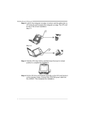
Connect the CPU FAN power cable into the JCFAN1. Motherboard Manual Step 2: Look for the triangular cut edge on socket, and the golden dot on the retention frame. Step 4: Put the CPU Fan and heatsink assembly on the CPU and buckle it on CPU should point forwards this triangular cut edge. This completes the installation. 6 Step 2-1: Step 2-2: Step 3: Hold the CPU down firmly, and then lower the lever to locked position to complete the installation. The CPU will fit only in the correct orientation.
Connect the CPU FAN power cable into the JCFAN1. Motherboard Manual Step 2: Look for the triangular cut edge on socket, and the golden dot on the retention frame. Step 4: Put the CPU Fan and heatsink assembly on the CPU and buckle it on CPU should point forwards this triangular cut edge. This completes the installation. 6 Step 2-1: Step 2-2: Step 3: Hold the CPU down firmly, and then lower the lever to locked position to complete the installation. The CPU will fit only in the correct orientation.
Setup Manual
Page 10
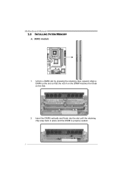
Align a DIMM on the slot so that the notch on the DIMM matches the break on the Slot. 2. Insert the DIMM vertically and firmly into the slot until the retaining chip snap back in place and the DIMM is properly seated. 8 Unlock a DIMM slot by pressing the retaining clips outward. DDR2 module 1. DD R2_A1 DD R2_B1 Motherboard Manual 2.3 INSTALLING SYSTEM MEMORY A.
Align a DIMM on the slot so that the notch on the DIMM matches the break on the Slot. 2. Insert the DIMM vertically and firmly into the slot until the retaining chip snap back in place and the DIMM is properly seated. 8 Unlock a DIMM slot by pressing the retaining clips outward. DDR2 module 1. DD R2_A1 DD R2_B1 Motherboard Manual 2.3 INSTALLING SYSTEM MEMORY A.
Setup Manual
Page 11
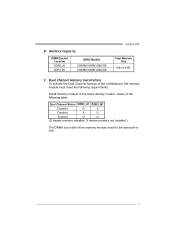
B. Dual Channel Memory Installation To activate the Dual Channel function of the motherboard, the memory module must be the same(x8 or x16) 9 Dual Channel Status DDR2_A1 DDR2_B1 Disabled O X Disabled X O Enabled O O (O means memory installed, X means memory not installed.) ... the memory module must meet the following table. Memory Capacity DIMM Socket Location DDR2_A1 DDR2_B1 DDR2 Module 256MB/512MB/1GB/2GB 256MB/512MB/1GB/2GB G31D-M7 Total Memory Size Max is 4GB. C.
B. Dual Channel Memory Installation To activate the Dual Channel function of the motherboard, the memory module must be the same(x8 or x16) 9 Dual Channel Status DDR2_A1 DDR2_B1 Disabled O X Disabled X O Enabled O O (O means memory installed, X means memory not installed.) ... the memory module must meet the following table. Memory Capacity DIMM Socket Location DDR2_A1 DDR2_B1 DDR2 Module 256MB/512MB/1GB/2GB 256MB/512MB/1GB/2GB G31D-M7 Total Memory Size Max is 4GB. C.
Setup Manual
Page 12
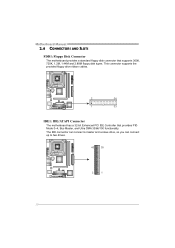
Motherboard Manual 2.4 CONNECTORS AND SLOTS FDD1: Floppy Disk Connector The motherboard provides a standard floppy disk connector that provides PIO Mode 0~4, Bus Master, and Ultra DMA 33/66/100 functionality. This connector supports the provided floppy drive ribbon cables. 2 34 1 33 IDE1: IDE/ATAPI Connector The motherboard has a 32-bit Enhanced PCI IDE Controller that supports 360K, 720K, 1.2M, 1.44M and 2.88M floppy disk types. The IDE connector can connect a master and a slave drive, so you can connect up to two drives. 40 39 2 1 10
Motherboard Manual 2.4 CONNECTORS AND SLOTS FDD1: Floppy Disk Connector The motherboard provides a standard floppy disk connector that provides PIO Mode 0~4, Bus Master, and Ultra DMA 33/66/100 functionality. This connector supports the provided floppy drive ribbon cables. 2 34 1 33 IDE1: IDE/ATAPI Connector The motherboard has a 32-bit Enhanced PCI IDE Controller that supports 360K, 720K, 1.2M, 1.44M and 2.88M floppy disk types. The IDE connector can connect a master and a slave drive, so you can connect up to two drives. 40 39 2 1 10
Setup Manual
Page 13
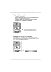
PCI stands for Peripheral Component Interconnect, and it is a bus standard for an aggregate of 8GB/s totally. - This PCI slot is equipped with 1 standard PCI slot. Maximum theoretical realized bandwidth of 2.5Gb/s on the data pins. - 2X bandwidth over the traditional PCI architecture. G31D-M7 PEX16_1: PCI-Express x16 Slot - PCI1 11 PEX16_1 PCI1: Peripheral Component Interconnect Slot This motherboard is designated as 32 bits. PCI-Express 1.0a compliant. - PCI-Express supports a raw bit-rate of 4GB/s simultaneously per direction, for expansion cards.
PCI stands for Peripheral Component Interconnect, and it is a bus standard for an aggregate of 8GB/s totally. - This PCI slot is equipped with 1 standard PCI slot. Maximum theoretical realized bandwidth of 2.5Gb/s on the data pins. - 2X bandwidth over the traditional PCI architecture. G31D-M7 PEX16_1: PCI-Express x16 Slot - PCI1 11 PEX16_1 PCI1: Peripheral Component Interconnect Slot This motherboard is designated as 32 bits. PCI-Express 1.0a compliant. - PCI-Express supports a raw bit-rate of 4GB/s simultaneously per direction, for expansion cards.
Setup Manual
Page 14
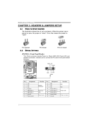
... closed 3.2 DETAIL SETTINGS Pin1-2 closed JPANEL1: Front Panel Header This 16-pin connector includes Power-on button 12 It allows user to set up jumpers. Motherboard Manual CHAPTER 3: HEADERS & JUMPERS SETUP 3.1 HOW TO SETUP JUMPERS The illustration shows how to connect the PC case's front panel switch functions. - PWR_LED On/Off...
... closed 3.2 DETAIL SETTINGS Pin1-2 closed JPANEL1: Front Panel Header This 16-pin connector includes Power-on button 12 It allows user to set up jumpers. Motherboard Manual CHAPTER 3: HEADERS & JUMPERS SETUP 3.1 HOW TO SETUP JUMPERS The illustration shows how to connect the PC case's front panel switch functions. - PWR_LED On/Off...
Setup Manual
Page 16
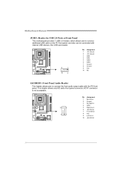
... Sense 7 Front Sense 8 Key 9 Left line in 10 Jack Sense 14 This header allows only HD audio front panel connector; Motherboard Manual JUSB3: Header for USB 2.0 Ports at Front Panel This motherboard provides 1 USB 2.0 header, which allows user to connect additional USB cable on the PC front panel, and also can be...
... Sense 7 Front Sense 8 Key 9 Left line in 10 Jack Sense 14 This header allows only HD audio front panel connector; Motherboard Manual JUSB3: Header for USB 2.0 Ports at Front Panel This motherboard provides 1 USB 2.0 header, which allows user to connect additional USB cable on the PC front panel, and also can be...
Setup Manual
Page 17
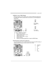
G31D-M7 JCMOS1: Clear CMOS Header Placing the jumper on the AC. 6. Set the jumper to "Pin 2-3 close ". 5. SATA1 SATA2 Pin Assignment 1 Ground 2 TX+ 3 TX4 Ground 5 RX6 .../s. Reset your desired password or clear the CMOS data. Wait for five seconds. 4. Set the jumper to "Pin 1-2 close ". 3. SATA1/SATA2: Serial ATA Connectors The motherboard has a PCI to avoid damaging the motherboard. 3 1 Pin 1-2 Close: Normal Operation (Default). 3 1 3 Pin 2-3 Close: 1 Clear CMOS data. ※ Clear CMOS Procedures: 1.
G31D-M7 JCMOS1: Clear CMOS Header Placing the jumper on the AC. 6. Set the jumper to "Pin 2-3 close ". 5. SATA1 SATA2 Pin Assignment 1 Ground 2 TX+ 3 TX4 Ground 5 RX6 .../s. Reset your desired password or clear the CMOS data. Wait for five seconds. 4. Set the jumper to "Pin 1-2 close ". 3. SATA1/SATA2: Serial ATA Connectors The motherboard has a PCI to avoid damaging the motherboard. 3 1 Pin 1-2 Close: Normal Operation (Default). 3 1 3 Pin 2-3 Close: 1 Clear CMOS data. ※ Clear CMOS Procedures: 1.
Setup Manual
Page 18
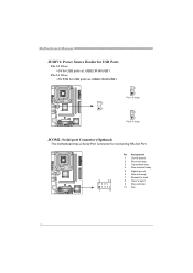
Motherboard Manual JUSBV1: Power Source Header for USB Ports Pin 1-2 Close: +5V for USB ports at JUSB2/JRJ45USB1. 3 1 3 1 Pin 1-2 close 3 1 Pin 2-3 close JCOM2: Serial port Connector (Optional) The motherboard has a Serial Port Connector for USB ports at JUSB2/JRJ45USB1. Pin 2-3 Close: +5V STB for connecting RS-232 Port. 2 10 1 9 Pin Assignment 1 Carrier detect 2 Received data 3 Transmitted data 4 Data terminal ready 5 Signal ground 6 Data set ready 7 Request to send 8 Clear to send 9 Ring indicator 10 Key 16
Motherboard Manual JUSBV1: Power Source Header for USB Ports Pin 1-2 Close: +5V for USB ports at JUSB2/JRJ45USB1. 3 1 3 1 Pin 1-2 close 3 1 Pin 2-3 close JCOM2: Serial port Connector (Optional) The motherboard has a Serial Port Connector for USB ports at JUSB2/JRJ45USB1. Pin 2-3 Close: +5V STB for connecting RS-232 Port. 2 10 1 9 Pin Assignment 1 Carrier detect 2 Received data 3 Transmitted data 4 Data terminal ready 5 Signal ground 6 Data set ready 7 Request to send 8 Clear to send 9 Ring indicator 10 Key 16
Setup Manual
Page 20
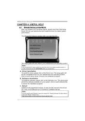
...the driver, please click on each software title to launch the installation program. The setup guide will list the software available for your motherboard and operating system. Click on the Driver icon. Software Installation To install the software, please click on the Manual icon to launch the..., we also provide manual in the Driver CD. Manual Aside from http://www.adobe.com /produ cts/a crobat /reads tep2 .html 18 Motherboard Manual CHAPTER 4: USEFUL HELP 4.1 DRIVER INSTALLATION NOTE After you installed your operating system, please insert the Fully Setup Driver CD into your optical...
...the driver, please click on each software title to launch the installation program. The setup guide will list the software available for your motherboard and operating system. Click on the Driver icon. Software Installation To install the software, please click on the Manual icon to launch the..., we also provide manual in the Driver CD. Manual Aside from http://www.adobe.com /produ cts/a crobat /reads tep2 .html 18 Motherboard Manual CHAPTER 4: USEFUL HELP 4.1 DRIVER INSTALLATION NOTE After you installed your operating system, please insert the Fully Setup Driver CD into your optical...
Setup Manual
Page 22
... saved .txt file, you to enter file name. Go to the following web http://www.biostar.com.tw/app/en-us/about/contact.php for your system information while using Outlook Express as your system information including motherboard/BIOS/CPU/video/ device/OS information. A warning dialog would appear asking for getting our...
... saved .txt file, you to enter file name. Go to the following web http://www.biostar.com.tw/app/en-us/about/contact.php for your system information while using Outlook Express as your system information including motherboard/BIOS/CPU/video/ device/OS information. A warning dialog would appear asking for getting our...
Setup Manual
Page 23
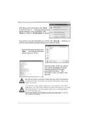
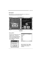
Choose the position to update your motherboard BIOS under Windows system. Click on this button, the saving dialog will show . After the saving process, finish dialog will show . AWARD BIOS Show current ... for AMI BIOS) Save current BIOS to a .bin file Update BIOS with a BIOS file Once click on OK to complete the BIOS Backup procedure. 21 G31D-M7 BIOS Update BIOS Update is a convenient utility which allows you to save file and enter file name. (We recommend that the file name should be...
Choose the position to update your motherboard BIOS under Windows system. Click on this button, the saving dialog will show . After the saving process, finish dialog will show . AWARD BIOS Show current ... for AMI BIOS) Save current BIOS to a .bin file Update BIOS with a BIOS file Once click on OK to complete the BIOS Backup procedure. 21 G31D-M7 BIOS Update BIOS Update is a convenient utility which allows you to save file and enter file name. (We recommend that the file name should be...
Setup Manual
Page 24
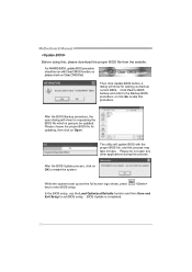
..., use the Load Optimized Defaults function and then Save and Exit Setup to enter BIOS setup. BIOS Update is going to the Backup BIOS procedure; Motherboard Manual Before doing this process. Click Yes for updating, then click on Open. After the BIOS Backup procedure, the open any other applications during this...
..., use the Load Optimized Defaults function and then Save and Exit Setup to enter BIOS setup. BIOS Update is going to the Backup BIOS procedure; Motherboard Manual Before doing this process. Click Yes for updating, then click on Open. After the BIOS Backup procedure, the open any other applications during this...
Setup Manual
Page 26
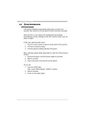
...cord from power supply for seconds. 3. Wait for seconds. 2. When the CPU is rotated normally. 3. CPU fan is over heated, the motherboard will shutdown automatically to relief the CPU protection function. 1. After confirmed, please follow steps below to avoid a damage of the CPU, and ...the system may not power on system for seconds. 3. Wait for seconds, that means the CPU protection function has been activated. Motherboard Manual 4.3 EXTRA INFORMATION CPU Overheated If the system shutdown automatically after power on again. Power on the system again. 24 Or you ...
...cord from power supply for seconds. 3. Wait for seconds. 2. When the CPU is rotated normally. 3. CPU fan is over heated, the motherboard will shutdown automatically to relief the CPU protection function. 1. After confirmed, please follow steps below to avoid a damage of the CPU, and ...the system may not power on system for seconds. 3. Wait for seconds, that means the CPU protection function has been activated. Motherboard Manual 4.3 EXTRA INFORMATION CPU Overheated If the system shutdown automatically after power on again. Power on the system again. 24 Or you ...
Setup Manual
Page 27
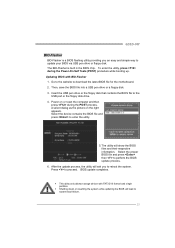
Go to the website to enter the utility. 5. Select the device contains the BIOS file and press to download the latest BIOS file for the motherboard. 2. After the update process, the utility will ask you an easy and simple way to reboot the system. Updating BIOS with FAT32/16 format ... the computer and then press during the Power-On Self Tests (POST) procedure while booting up. z This utility only allows storage device with BIO-Flasher 1. G31D-M7 BIO-Flasher BIO-Flasher is built in the BIOS chip. Then, save the BIOS file into a USB pen drive or a floppy disk. 3. BIOS update ...
Go to the website to enter the utility. 5. Select the device contains the BIOS file and press to download the latest BIOS file for the motherboard. 2. After the update process, the utility will ask you an easy and simple way to reboot the system. Updating BIOS with FAT32/16 format ... the computer and then press during the Power-On Self Tests (POST) procedure while booting up. z This utility only allows storage device with BIO-Flasher 1. G31D-M7 BIO-Flasher BIO-Flasher is built in the BIOS chip. Then, save the BIOS file into a USB pen drive or a floppy disk. 3. BIOS update ...
Setup Manual
Page 28
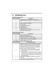
...Troubleshooting POST BIOS Beep Codes Number of Beeps Troubleshooting Action 1, 3 Reseat the memory, or replace with the system. Before declaring the motherboard beyond all expansion cards except the video adapter. Remove all hope, eliminate the possibility of interference by a malfunctioning add-in card. z... is an integrated part of the system board, the board may be faulty. 26 If the video adapter is causing the malfunction. Motherboard Manual 4.4 AMI BIOS BEEP CODE Boot Block Beep Codes Number of Beeps Description 1 No media present. (Insert diskette in floppy drive...
...Troubleshooting POST BIOS Beep Codes Number of Beeps Troubleshooting Action 1, 3 Reseat the memory, or replace with the system. Before declaring the motherboard beyond all expansion cards except the video adapter. Remove all hope, eliminate the possibility of interference by a malfunctioning add-in card. z... is an integrated part of the system board, the board may be faulty. 26 If the video adapter is causing the malfunction. Motherboard Manual 4.4 AMI BIOS BEEP CODE Boot Block Beep Codes Number of Beeps Description 1 No media present. (Insert diskette in floppy drive...


