Setup Manual
Page 3
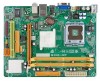
CHAPTER 1: INTRODUCTION G31D-M7 1.1 BEFORE YOU START Thank you take the motherboard out from anti-static bag, ground yourself properly by area or your motherboard version. 1 Before you start installing the motherboard, please make sure you follow the instructions below: „ Prepare a dry and stable working environment with ... any safely grounded appliance, or use grounded wrist strap to remove the static charge. „ Avoid touching the components on motherboard or the rear side of the board unless necessary. Loose parts will cause short circuits which may damage the equipment. „...
CHAPTER 1: INTRODUCTION G31D-M7 1.1 BEFORE YOU START Thank you take the motherboard out from anti-static bag, ground yourself properly by area or your motherboard version. 1 Before you start installing the motherboard, please make sure you follow the instructions below: „ Prepare a dry and stable working environment with ... any safely grounded appliance, or use grounded wrist strap to remove the static charge. „ Avoid touching the components on motherboard or the rear side of the board unless necessary. Loose parts will cause short circuits which may damage the equipment. „...
Setup Manual
Page 4
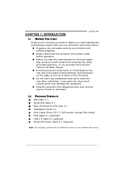
... connector Connector Printer Port Connector Serial port Connector (Optional) x1 Each connector supports 2 Floppy drives x1 Each connector supports 1 Printer port x1 Connects to 3.0 Gb/s. Motherboard Manual 1.3 MOTHERBOARD FEATURES SPEC LGA 775 Supports Hyper-Threading / Execute Disable Bit / Intel Core2Duo / Pentium Dual-Core / Enhanced Intel SpeedStep® / Intel Architecture-64 / CPU Celeron Dual...
... connector Connector Printer Port Connector Serial port Connector (Optional) x1 Each connector supports 2 Floppy drives x1 Each connector supports 1 Printer port x1 Connects to 3.0 Gb/s. Motherboard Manual 1.3 MOTHERBOARD FEATURES SPEC LGA 775 Supports Hyper-Threading / Execute Disable Bit / Intel Core2Duo / Pentium Dual-Core / Enhanced Intel SpeedStep® / Intel Architecture-64 / CPU Celeron Dual...
Setup Manual
Page 6
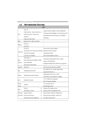
Motherboard Manual 1.5 MOTHERBOARD LAYOUT JKBMS1 LGA775 CPU1 JCFAN1 J ATXPWR 1 J ATX PWR 2 JVGA 1 DDR2_ A 1 DDR2_ B 1 JUSB V1 IDE 1 JUSB2 BAT1 JRJ45USB1 Intel G31 JAUDIO1 JAUDIOF1 LAN Super I/O JCOM2 (Optional) PEX16_1 BIO S J USB3 FDD1 PCI1 Codec JPRNT1 JPANEL1 J CMOS1 Note: ■ represents the 1st pin. S ATA 1 Intel ICH7 SATA2 4
Motherboard Manual 1.5 MOTHERBOARD LAYOUT JKBMS1 LGA775 CPU1 JCFAN1 J ATXPWR 1 J ATX PWR 2 JVGA 1 DDR2_ A 1 DDR2_ B 1 JUSB V1 IDE 1 JUSB2 BAT1 JRJ45USB1 Intel G31 JAUDIO1 JAUDIOF1 LAN Super I/O JCOM2 (Optional) PEX16_1 BIO S J USB3 FDD1 PCI1 Codec JPRNT1 JPANEL1 J CMOS1 Note: ■ represents the 1st pin. S ATA 1 Intel ICH7 SATA2 4
Setup Manual
Page 8
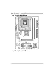
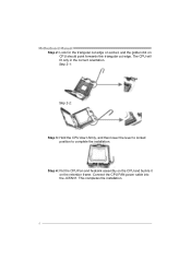
Connect the CPU FAN power cable into the JCFAN1. This completes the installation. 6 Step 2-1: Step 2-2: Step 3: Hold the CPU down firmly, and then lower the lever to locked position to complete the installation. Motherboard Manual Step 2: Look for the triangular cut edge on socket, and the golden dot on the retention frame. The CPU will fit only in the correct orientation. Step 4: Put the CPU Fan and heatsink assembly on the CPU and buckle it on CPU should point forwards this triangular cut edge.
Connect the CPU FAN power cable into the JCFAN1. This completes the installation. 6 Step 2-1: Step 2-2: Step 3: Hold the CPU down firmly, and then lower the lever to locked position to complete the installation. Motherboard Manual Step 2: Look for the triangular cut edge on socket, and the golden dot on the retention frame. The CPU will fit only in the correct orientation. Step 4: Put the CPU Fan and heatsink assembly on the CPU and buckle it on CPU should point forwards this triangular cut edge.
Setup Manual
Page 10
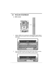
Insert the DIMM vertically and firmly into the slot until the retaining chip snap back in place and the DIMM is properly seated. 8 Align a DIMM on the slot so that the notch on the DIMM matches the break on the Slot. 2. DD R2_A1 DD R2_B1 Motherboard Manual 2.3 INSTALLING SYSTEM MEMORY A. Unlock a DIMM slot by pressing the retaining clips outward. DDR2 module 1.
Insert the DIMM vertically and firmly into the slot until the retaining chip snap back in place and the DIMM is properly seated. 8 Align a DIMM on the slot so that the notch on the DIMM matches the break on the Slot. 2. DD R2_A1 DD R2_B1 Motherboard Manual 2.3 INSTALLING SYSTEM MEMORY A. Unlock a DIMM slot by pressing the retaining clips outward. DDR2 module 1.
Setup Manual
Page 12
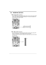
This connector supports the provided floppy drive ribbon cables. 2 34 1 33 IDE1: IDE/ATAPI Connector The motherboard has a 32-bit Enhanced PCI IDE Controller that supports 360K, 720K, 1.2M, 1.44M and 2.88M floppy disk types. The IDE connector can connect a master and a slave drive, so you can connect up to two drives. 40 39 2 1 10 Motherboard Manual 2.4 CONNECTORS AND SLOTS FDD1: Floppy Disk Connector The motherboard provides a standard floppy disk connector that provides PIO Mode 0~4, Bus Master, and Ultra DMA 33/66/100 functionality.
This connector supports the provided floppy drive ribbon cables. 2 34 1 33 IDE1: IDE/ATAPI Connector The motherboard has a 32-bit Enhanced PCI IDE Controller that supports 360K, 720K, 1.2M, 1.44M and 2.88M floppy disk types. The IDE connector can connect a master and a slave drive, so you can connect up to two drives. 40 39 2 1 10 Motherboard Manual 2.4 CONNECTORS AND SLOTS FDD1: Floppy Disk Connector The motherboard provides a standard floppy disk connector that provides PIO Mode 0~4, Bus Master, and Ultra DMA 33/66/100 functionality.
Setup Manual
Page 14
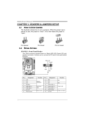
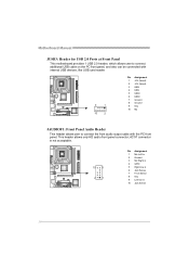
When the jumper cap is "open". It allows user to set up jumpers. Motherboard Manual CHAPTER 3: HEADERS & JUMPERS SETUP 3.1 HOW TO SETUP JUMPERS The illustration shows how to connect the PC case's front panel switch functions. - PWR_LED On/Off 9 ++ 16 1 + 8 ...
When the jumper cap is "open". It allows user to set up jumpers. Motherboard Manual CHAPTER 3: HEADERS & JUMPERS SETUP 3.1 HOW TO SETUP JUMPERS The illustration shows how to connect the PC case's front panel switch functions. - PWR_LED On/Off 9 ++ 16 1 + 8 ...
Setup Manual
Page 16
Motherboard Manual JUSB3: Header for USB 2.0 Ports at Front Panel This motherboard provides 1 USB 2.0 header, which allows user to connect additional USB cable on the PC front panel, and also can be connected with internal USB devices, ...
Motherboard Manual JUSB3: Header for USB 2.0 Ports at Front Panel This motherboard provides 1 USB 2.0 header, which allows user to connect additional USB cable on the PC front panel, and also can be connected with internal USB devices, ...
Setup Manual
Page 18
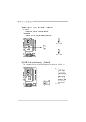
Pin 2-3 Close: +5V STB for connecting RS-232 Port. 2 10 1 9 Pin Assignment 1 Carrier detect 2 Received data 3 Transmitted data 4 Data terminal ready 5 Signal ground 6 Data set ready 7 Request to send 8 Clear to send 9 Ring indicator 10 Key 16 Motherboard Manual JUSBV1: Power Source Header for USB Ports Pin 1-2 Close: +5V for USB ports at JUSB2/JRJ45USB1. 3 1 3 1 Pin 1-2 close 3 1 Pin 2-3 close JCOM2: Serial port Connector (Optional) The motherboard has a Serial Port Connector for USB ports at JUSB2/JRJ45USB1.
Pin 2-3 Close: +5V STB for connecting RS-232 Port. 2 10 1 9 Pin Assignment 1 Carrier detect 2 Received data 3 Transmitted data 4 Data terminal ready 5 Signal ground 6 Data set ready 7 Request to send 8 Clear to send 9 Ring indicator 10 Key 16 Motherboard Manual JUSBV1: Power Source Header for USB Ports Pin 1-2 Close: +5V for USB ports at JUSB2/JRJ45USB1. 3 1 3 1 Pin 1-2 close 3 1 Pin 2-3 close JCOM2: Serial port Connector (Optional) The motherboard has a Serial Port Connector for USB ports at JUSB2/JRJ45USB1.
Setup Manual
Page 20
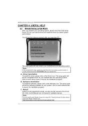
...cts/a crobat /reads tep2 .html 18 A. B. Note: You will auto detect your motherboard and operating system. Driver Installation To install the driver, please click on the Software icon. C. Click on the Manual icon to browse for your system, click on each software title to locate and execute...If this window didn't show up after you insert the CD The setup guide will need Acrobat Reader to launch the installation program. Motherboard Manual CHAPTER 4: USEFUL HELP 4.1 DRIVER INSTALLATION NOTE After you installed your operating system, please insert the Fully Setup Driver CD into your...
...cts/a crobat /reads tep2 .html 18 A. B. Note: You will auto detect your motherboard and operating system. Driver Installation To install the driver, please click on the Software icon. C. Click on the Manual icon to browse for your system, click on each software title to locate and execute...If this window didn't show up after you insert the CD The setup guide will need Acrobat Reader to launch the installation program. Motherboard Manual CHAPTER 4: USEFUL HELP 4.1 DRIVER INSTALLATION NOTE After you installed your operating system, please insert the Fully Setup Driver CD into your...
Setup Manual
Page 22
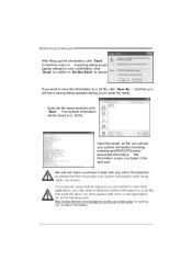
... information to a .txt file and send the file to our tech support with any other e-mail application. Go to the following web http://www.biostar.com.tw/app/en-us/about/contact.php for your default e-mail client application, you to enter file name. We will see a saving dialog... appear asking for getting our contact information. 20 Your system information will see your system information while using Outlook Express as your confirmation; Motherboard Manual After filling up this information to a .txt file, click "Save As..." This information is also concluded in the sent mail.
... information to a .txt file and send the file to our tech support with any other e-mail application. Go to the following web http://www.biostar.com.tw/app/en-us/about/contact.php for your default e-mail client application, you to enter file name. We will see a saving dialog... appear asking for getting our contact information. 20 Your system information will see your system information while using Outlook Express as your confirmation; Motherboard Manual After filling up this information to a .txt file, click "Save As..." This information is also concluded in the sent mail.
Setup Manual
Page 24
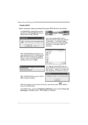
... on Clear CMOS first. In the BIOS setup, use the Load Optimized Defaults function and then Save and Exit Setup to the Backup BIOS procedure; Motherboard Manual Before doing this process. or click No to restart the system. After the BIOS Update process, click on OK to skip this process may take...
... on Clear CMOS first. In the BIOS setup, use the Load Optimized Defaults function and then Save and Exit Setup to the Backup BIOS procedure; Motherboard Manual Before doing this process. or click No to restart the system. After the BIOS Update process, click on OK to skip this process may take...
Setup Manual
Page 26
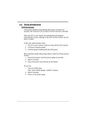
... on again. CPU fan speed is placed evenly with the CPU speed. Wait for seconds. 3. Plug in the power cord and boot up the system. Motherboard Manual 4.3 EXTRA INFORMATION CPU Overheated If the system shutdown automatically after power on system for seconds. 2. In this case, please double check: 1. After confirmed, please follow...
... on again. CPU fan speed is placed evenly with the CPU speed. Wait for seconds. 3. Plug in the power cord and boot up the system. Motherboard Manual 4.3 EXTRA INFORMATION CPU Overheated If the system shutdown automatically after power on system for seconds. 2. In this case, please double check: 1. After confirmed, please follow...
Setup Manual
Page 28
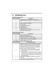
... generated when all hope, eliminate the possibility of interference by a malfunctioning add-in cards is causing the malfunction. Before declaring the motherboard beyond all other expansion 6, 7 cards are absent, consult your system manufacturer. z If beep codes are generated when all expansion ...file size error 13 BIOS ROM image mismatch (file layout does not match image present in card, replace or 8 reseat the video adapter. Motherboard Manual 4.4 AMI BIOS BEEP CODE Boot Block Beep Codes Number of Beeps Description 1 No media present. (Insert diskette in floppy drive A:) 2...
... generated when all hope, eliminate the possibility of interference by a malfunctioning add-in cards is causing the malfunction. Before declaring the motherboard beyond all other expansion 6, 7 cards are absent, consult your system manufacturer. z If beep codes are generated when all expansion ...file size error 13 BIOS ROM image mismatch (file layout does not match image present in card, replace or 8 reseat the video adapter. Motherboard Manual 4.4 AMI BIOS BEEP CODE Boot Block Beep Codes Number of Beeps Description 1 No media present. (Insert diskette in floppy drive A:) 2...
Bios Setup
Page 2
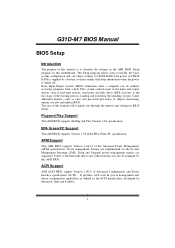
... features, such as virus and password prot ection or chipset fine-tuning options are also included in BIOS Setup. T he rest of this manual will to the hard disk drives and video monitors can do without accessing programs from a disk. APM Support T his AMI BIOS supports the...mouse, serial ports and disk drives. G31D-M7 BIOS Manual BIOS Setup Introduction T he purpose of this manual is turned off. ACPI Support AMI ACPI BIOS support Version 1.0/2.0 of the input and output devices such as defined in the AMI BIOS Setup program on this motherboard. EPA Green PC Support T his system...
... features, such as virus and password prot ection or chipset fine-tuning options are also included in BIOS Setup. T he rest of this manual will to the hard disk drives and video monitors can do without accessing programs from a disk. APM Support T his AMI BIOS supports the...mouse, serial ports and disk drives. G31D-M7 BIOS Manual BIOS Setup Introduction T he purpose of this manual is turned off. ACPI Support AMI ACPI BIOS support Version 1.0/2.0 of the input and output devices such as defined in the AMI BIOS Setup program on this motherboard. EPA Green PC Support T his system...
Bios Setup
Page 3
G31D-M7 BIOS Manual PCI Bus Support T his AMI BIOS supports the Intel CPU. z For better system perform ance, the BIOS firmware is supported. If the system becomes unstable after changing any system damage that particular menu are at the top right corner, and this manual is subject to ... Navigation Keys Notice z T he BIOS information described in this manual is for most conditions to enter the BIOS setup utility. Navigation Keys for any mistakes found in this is providing a brief description of the motherboard. Use Load Setup Default under the Exit Menu. DRAM S ...
G31D-M7 BIOS Manual PCI Bus Support T his AMI BIOS supports the Intel CPU. z For better system perform ance, the BIOS firmware is supported. If the system becomes unstable after changing any system damage that particular menu are at the top right corner, and this manual is subject to ... Navigation Keys Notice z T he BIOS information described in this manual is for most conditions to enter the BIOS setup utility. Navigation Keys for any mistakes found in this is providing a brief description of the motherboard. Use Load Setup Default under the Exit Menu. DRAM S ...
Bios Setup
Page 15
...to invoke VGA BIOS post on S3 Resume T he item allows you control the energy lake feature. Options: Disabled (Default) / Enabled 14 G31D-M7 BIOS Manual Suspend mode T he item allows you to select the version of ACPI. To run in the Root System Description T able (RSDT ) ..., monitor or mouse. Options: Disabled (Default) / Enabled Energy Lake Feature T his item allows you to determine whether to enable or disable the motherboard's APIC (Advan ced Programmable Interrupt Controller). Options: Enabled (Default) / Disabled AMI OEMB table Set this value to allow the ACPIBIOS to add a...
...to invoke VGA BIOS post on S3 Resume T he item allows you control the energy lake feature. Options: Disabled (Default) / Enabled 14 G31D-M7 BIOS Manual Suspend mode T he item allows you to select the version of ACPI. To run in the Root System Description T able (RSDT ) ..., monitor or mouse. Options: Disabled (Default) / Enabled Energy Lake Feature T his item allows you to determine whether to enable or disable the motherboard's APIC (Advan ced Programmable Interrupt Controller). Options: Enabled (Default) / Disabled AMI OEMB table Set this value to allow the ACPIBIOS to add a...
Bios Setup
Page 16
Options: FED00000h (Default) / FED01000h / FED02000h / FED03000h Resume On Ring T his item allows you control the wake on motherboard to enable i f applicable. Set the Wake on LAN (WOL) jumper on ring function. Options: Disabled (Default) / Enabled Resume On RTC Alarm When " Enabled", you select ... PME# When you can choose which date the system will boot up. 15 For this function to work, you to enable or disabled the HPET. G31D-M7 BIOS Manual APIC ACPI SCI IRQ Options: Disabled (Default) / Enabled USB Dev ice Wakeup from S3/S4 T his item allows you to set the date and...
Options: FED00000h (Default) / FED01000h / FED02000h / FED03000h Resume On Ring T his item allows you control the wake on motherboard to enable i f applicable. Set the Wake on LAN (WOL) jumper on ring function. Options: Disabled (Default) / Enabled Resume On RTC Alarm When " Enabled", you select ... PME# When you can choose which date the system will boot up. 15 For this function to work, you to enable or disabled the HPET. G31D-M7 BIOS Manual APIC ACPI SCI IRQ Options: Disabled (Default) / Enabled USB Dev ice Wakeup from S3/S4 T his item allows you to set the date and...


