Setup Manual
Page 1
... brand and product names are designed to provide reasonable protection against harmful interference in accordance with respect to revise this user's manual is not allowed without notice and we will not occur in a particular installation. There is no representations or warranties with... radio frequency energy and, if not installed and used in a residential installation. G31D-M7 Setup Manual FCC Information and Copyright This equipment has been tested and found in this user's manual. These limits are trademarks of merchantability or fitness for any mistakes found to comply...
... brand and product names are designed to provide reasonable protection against harmful interference in accordance with respect to revise this user's manual is not allowed without notice and we will not occur in a particular installation. There is no representations or warranties with... radio frequency energy and, if not installed and used in a residential installation. G31D-M7 Setup Manual FCC Information and Copyright This equipment has been tested and found in this user's manual. These limits are trademarks of merchantability or fitness for any mistakes found to comply...
Setup Manual
Page 3
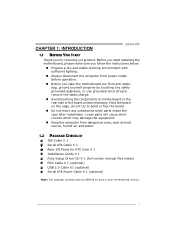
...disconnect the computer from power outlet before operation. „ Before you for ATX Case X 1 Installation Guide X 1 Fully Setup Driver CD X 1 (full version manual files inside) FDD Cable X 1 (optional) USB 2.0 Cable X1 (optional) Serial ATA Power Cable X 1 (optional) Note: The package contents may be differed...strap to bend or flex the board. „ Do not leave any unfastened small parts inside the case after installation. CHAPTER 1: INTRODUCTION G31D-M7 1.1 BEFORE YOU START Thank you take the motherboard out from dangerous area, such as heat source, humid air and water. 1.2 PACKAGE ...
...disconnect the computer from power outlet before operation. „ Before you for ATX Case X 1 Installation Guide X 1 Fully Setup Driver CD X 1 (full version manual files inside) FDD Cable X 1 (optional) USB 2.0 Cable X1 (optional) Serial ATA Power Cable X 1 (optional) Note: The package contents may be differed...strap to bend or flex the board. „ Do not leave any unfastened small parts inside the case after installation. CHAPTER 1: INTRODUCTION G31D-M7 1.1 BEFORE YOU START Thank you take the motherboard out from dangerous area, such as heat source, humid air and water. 1.2 PACKAGE ...
Setup Manual
Page 4
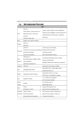
... Connector Printer Port Connector Serial port Connector (Optional) x1 Each connector supports 2 Floppy drives x1 Each connector supports 1 Printer port x1 Connects to 3.0 Gb/s. Motherboard Manual 1.3 MOTHERBOARD FEATURES SPEC LGA 775 Supports Hyper-Threading / Execute Disable Bit / Intel Core2Duo / Pentium Dual-Core / Enhanced Intel SpeedStep® / Intel Architecture-64 / CPU Celeron...
... Connector Printer Port Connector Serial port Connector (Optional) x1 Each connector supports 2 Floppy drives x1 Each connector supports 1 Printer port x1 Connects to 3.0 Gb/s. Motherboard Manual 1.3 MOTHERBOARD FEATURES SPEC LGA 775 Supports Hyper-Threading / Execute Disable Bit / Intel Core2Duo / Pentium Dual-Core / Enhanced Intel SpeedStep® / Intel Architecture-64 / CPU Celeron...
Setup Manual
Page 6
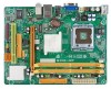
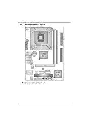
Motherboard Manual 1.5 MOTHERBOARD LAYOUT JKBMS1 LGA775 CPU1 JCFAN1 J ATXPWR 1 J ATX PWR 2 JVGA 1 DDR2_ A 1 DDR2_ B 1 JUSB V1 IDE 1 JUSB2 BAT1 JRJ45USB1 Intel G31 JAUDIO1 JAUDIOF1 LAN Super I/O JCOM2 (Optional) PEX16_1 BIO S J USB3 FDD1 PCI1 Codec JPRNT1 JPANEL1 J CMOS1 Note: ■ represents the 1st pin. S ATA 1 Intel ICH7 SATA2 4
Motherboard Manual 1.5 MOTHERBOARD LAYOUT JKBMS1 LGA775 CPU1 JCFAN1 J ATXPWR 1 J ATX PWR 2 JVGA 1 DDR2_ A 1 DDR2_ B 1 JUSB V1 IDE 1 JUSB2 BAT1 JRJ45USB1 Intel G31 JAUDIO1 JAUDIOF1 LAN Super I/O JCOM2 (Optional) PEX16_1 BIO S J USB3 FDD1 PCI1 Codec JPRNT1 JPANEL1 J CMOS1 Note: ■ represents the 1st pin. S ATA 1 Intel ICH7 SATA2 4
Setup Manual
Page 8
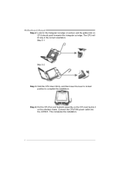
The CPU will fit only in the correct orientation. Step 4: Put the CPU Fan and heatsink assembly on the CPU and buckle it on CPU should point forwards this triangular cut edge. Connect the CPU FAN power cable into the JCFAN1. This completes the installation. 6 Motherboard Manual Step 2: Look for the triangular cut edge on socket, and the golden dot on the retention frame. Step 2-1: Step 2-2: Step 3: Hold the CPU down firmly, and then lower the lever to locked position to complete the installation.
The CPU will fit only in the correct orientation. Step 4: Put the CPU Fan and heatsink assembly on the CPU and buckle it on CPU should point forwards this triangular cut edge. Connect the CPU FAN power cable into the JCFAN1. This completes the installation. 6 Motherboard Manual Step 2: Look for the triangular cut edge on socket, and the golden dot on the retention frame. Step 2-1: Step 2-2: Step 3: Hold the CPU down firmly, and then lower the lever to locked position to complete the installation.
Setup Manual
Page 10
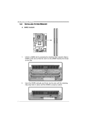
DD R2_A1 DD R2_B1 Motherboard Manual 2.3 INSTALLING SYSTEM MEMORY A. Unlock a DIMM slot by pressing the retaining clips outward. Align a DIMM on the slot so that the notch on the DIMM matches the break on the Slot. 2. Insert the DIMM vertically and firmly into the slot until the retaining chip snap back in place and the DIMM is properly seated. 8 DDR2 module 1.
DD R2_A1 DD R2_B1 Motherboard Manual 2.3 INSTALLING SYSTEM MEMORY A. Unlock a DIMM slot by pressing the retaining clips outward. Align a DIMM on the slot so that the notch on the DIMM matches the break on the Slot. 2. Insert the DIMM vertically and firmly into the slot until the retaining chip snap back in place and the DIMM is properly seated. 8 DDR2 module 1.
Setup Manual
Page 12
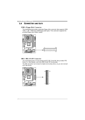
Motherboard Manual 2.4 CONNECTORS AND SLOTS FDD1: Floppy Disk Connector The motherboard provides a standard floppy disk connector that provides PIO Mode 0~4, Bus Master, and Ultra DMA 33/66/100 functionality. This connector supports the provided floppy drive ribbon cables. 2 34 1 33 IDE1: IDE/ATAPI Connector The motherboard has a 32-bit Enhanced PCI IDE Controller that supports 360K, 720K, 1.2M, 1.44M and 2.88M floppy disk types. The IDE connector can connect a master and a slave drive, so you can connect up to two drives. 40 39 2 1 10
Motherboard Manual 2.4 CONNECTORS AND SLOTS FDD1: Floppy Disk Connector The motherboard provides a standard floppy disk connector that provides PIO Mode 0~4, Bus Master, and Ultra DMA 33/66/100 functionality. This connector supports the provided floppy drive ribbon cables. 2 34 1 33 IDE1: IDE/ATAPI Connector The motherboard has a 32-bit Enhanced PCI IDE Controller that supports 360K, 720K, 1.2M, 1.44M and 2.88M floppy disk types. The IDE connector can connect a master and a slave drive, so you can connect up to two drives. 40 39 2 1 10
Setup Manual
Page 14
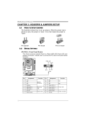
... LED, and speaker connection. When the jumper cap is placed on pins, the jumper is "close", if not, that means the jumper is "open". Motherboard Manual CHAPTER 3: HEADERS & JUMPERS SETUP 3.1 HOW TO SETUP JUMPERS The illustration shows how to connect the PC case's front panel switch functions. - It allows user to...
... LED, and speaker connection. When the jumper cap is placed on pins, the jumper is "close", if not, that means the jumper is "open". Motherboard Manual CHAPTER 3: HEADERS & JUMPERS SETUP 3.1 HOW TO SETUP JUMPERS The illustration shows how to connect the PC case's front panel switch functions. - It allows user to...
Setup Manual
Page 16
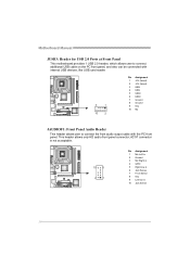
... Assignment 1 Mic Left in 2 Ground 3 Mic Right in 4 GPIO 5 Right line in 6 Jack Sense 7 Front Sense 8 Key 9 Left line in 10 Jack Sense 14 Motherboard Manual JUSB3: Header for USB 2.0 Ports at Front Panel This motherboard provides 1 USB 2.0 header, which allows user to connect additional USB cable on the PC front...
... Assignment 1 Mic Left in 2 Ground 3 Mic Right in 4 GPIO 5 Right line in 6 Jack Sense 7 Front Sense 8 Key 9 Left line in 10 Jack Sense 14 Motherboard Manual JUSB3: Header for USB 2.0 Ports at Front Panel This motherboard provides 1 USB 2.0 header, which allows user to connect additional USB cable on the PC front...
Setup Manual
Page 18
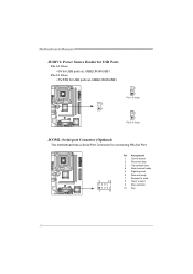
Motherboard Manual JUSBV1: Power Source Header for USB Ports Pin 1-2 Close: +5V for connecting RS-232 Port. 2 10 1 9 Pin Assignment 1 Carrier detect 2 Received data 3 Transmitted data 4 Data terminal ready 5 Signal ground 6 Data set ready 7 Request to send 8 Clear to send 9 Ring indicator 10 Key 16 Pin 2-3 Close: +5V STB for USB ports at JUSB2/JRJ45USB1. 3 1 3 1 Pin 1-2 close 3 1 Pin 2-3 close JCOM2: Serial port Connector (Optional) The motherboard has a Serial Port Connector for USB ports at JUSB2/JRJ45USB1.
Motherboard Manual JUSBV1: Power Source Header for USB Ports Pin 1-2 Close: +5V for connecting RS-232 Port. 2 10 1 9 Pin Assignment 1 Carrier detect 2 Received data 3 Transmitted data 4 Data terminal ready 5 Signal ground 6 Data set ready 7 Request to send 8 Clear to send 9 Ring indicator 10 Key 16 Pin 2-3 Close: +5V STB for USB ports at JUSB2/JRJ45USB1. 3 1 3 1 Pin 1-2 close 3 1 Pin 2-3 close JCOM2: Serial port Connector (Optional) The motherboard has a Serial Port Connector for USB ports at JUSB2/JRJ45USB1.
Setup Manual
Page 20
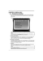
... your operating system, please insert the Fully Setup Driver CD into your system, click on each device driver to browse for available manual. Driver Installation To install the driver, please click on each software title to launch the installation program. B. C. Please download the... latest version of Acrobat Reader software from the paperback manual, we also provide manual in the Driver CD. Click on the Driver icon. Note: You will list the software available for your optical drive ...
... your operating system, please insert the Fully Setup Driver CD into your system, click on each device driver to browse for available manual. Driver Installation To install the driver, please click on each software title to launch the installation program. B. C. Please download the... latest version of Acrobat Reader software from the paperback manual, we also provide manual in the Driver CD. Click on the Driver icon. Note: You will list the software available for your optical drive ...
Setup Manual
Page 22
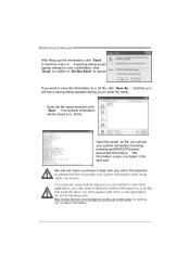
... using eHot-Line service. Your system information will not share customer's data with other third parties, so please feel free to provide your confirmation; Motherboard Manual After filling up this information to a .txt file, click "Save As..." click "Send" to confirm or "Do Not Send" to the following... web http://www.biostar.com.tw/app/en-us/about/contact.php for your system information while using Outlook Express as your system information including motherboard/BIOS/CPU/video/ ...
... using eHot-Line service. Your system information will not share customer's data with other third parties, so please feel free to provide your confirmation; Motherboard Manual After filling up this information to a .txt file, click "Save As..." click "Send" to confirm or "Do Not Send" to the following... web http://www.biostar.com.tw/app/en-us/about/contact.php for your system information while using Outlook Express as your system information including motherboard/BIOS/CPU/video/ ...
Setup Manual
Page 24
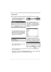
... Load Optimized Defaults function and then Save and Exit Setup to enter BIOS setup. After the BIOS Update process, click on Clear CMOS first. Motherboard Manual Before doing this process. After the BIOS Backup procedure, the open any other applications during this , please download the proper BIOS file from the website...
... Load Optimized Defaults function and then Save and Exit Setup to enter BIOS setup. After the BIOS Update process, click on Clear CMOS first. Motherboard Manual Before doing this process. After the BIOS Backup procedure, the open any other applications during this , please download the proper BIOS file from the website...
Setup Manual
Page 25
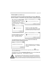
...different from internet. The programming procedure may be changed without notice. All the information and content above are subject to reboot the system. G31D-M7 (for your BIOS has been the latest version. Download completes; Click Yes to exit BIOS setup. the utility will ask you that...Click OK to proceed. While the system boots up and the full screen logo shows, press key to the internet before using this manual. 23 make any operation during the programming process. After clicking on board may take minutes, please do not make sure that your ...
...different from internet. The programming procedure may be changed without notice. All the information and content above are subject to reboot the system. G31D-M7 (for your BIOS has been the latest version. Download completes; Click Yes to exit BIOS setup. the utility will ask you that...Click OK to proceed. While the system boots up and the full screen logo shows, press key to the internet before using this manual. 23 make any operation during the programming process. After clicking on board may take minutes, please do not make sure that your ...
Setup Manual
Page 26
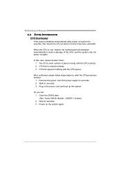
...: 1. When the CPU is fulfilling with the CPU surface. 2. Wait for seconds. 2. Wait for seconds, that means the CPU protection function has been activated. Motherboard Manual 4.3 EXTRA INFORMATION CPU Overheated If the system shutdown automatically after power on the system again. 24
...: 1. When the CPU is fulfilling with the CPU surface. 2. Wait for seconds. 2. Wait for seconds, that means the CPU protection function has been activated. Motherboard Manual 4.3 EXTRA INFORMATION CPU Overheated If the system shutdown automatically after power on the system again. 24
Setup Manual
Page 28
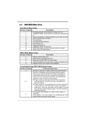
... other expansion 6, 7 cards are absent, consult your system manufacturer. Remove all other expansion cards are absent, one at a time until the problem happens again. Motherboard Manual 4.4 AMI BIOS BEEP CODE Boot Block Beep Codes Number of Beeps Description 1 No media present. (Insert diskette in floppy drive A:) 2 "AMIBOOT.ROM" file not found...
... other expansion 6, 7 cards are absent, consult your system manufacturer. Remove all other expansion cards are absent, one at a time until the problem happens again. Motherboard Manual 4.4 AMI BIOS BEEP CODE Boot Block Beep Codes Number of Beeps Description 1 No media present. (Insert diskette in floppy drive A:) 2 "AMIBOOT.ROM" file not found...
Bios Setup
Page 2
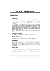
G31D-M7 BIOS Manual BIOS Setup Introduction T he purpose of CMOS RAM is supplied by a ...in the ACPI specification, developed by this motherboard. Plug and Pla y Support T his system controls most of this manual will to CMOS RAM. Power to the hard disk drives and video monitors can do without accessing programs from a ... T his AMI BIOS supports Version 1.03 of the Advanced Power Management (APM) speci fication. T he power of this manual is turned off. T his AMI BIOS supports the Plug and Play Version 1.0A specification. Power management features are supported....
G31D-M7 BIOS Manual BIOS Setup Introduction T he purpose of CMOS RAM is supplied by a ...in the ACPI specification, developed by this motherboard. Plug and Pla y Support T his system controls most of this manual will to CMOS RAM. Power to the hard disk drives and video monitors can do without accessing programs from a ... T his AMI BIOS supports Version 1.03 of the Advanced Power Management (APM) speci fication. T he power of this manual is turned off. T his AMI BIOS supports the Plug and Play Version 1.0A specification. Power management features are supported....
Bios Setup
Page 3
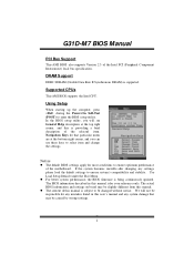
...any system damage that particular menu are at the top right corner, and this manual is supported. The actual BIOS information and settings on board may be slightly different from this manual is subject to ensure system's compatibility and stability. Supported CP Us T his AMI.... Navigation Keys for any mistakes found in this is being continuously updated. G31D-M7 BIOS Manual PCI Bus Support T his AMI BIOS supports the Intel CPU. T he BIOS information described in this user's manual and any settings, please load the default settings to be chang ed without...
...any system damage that particular menu are at the top right corner, and this manual is supported. The actual BIOS information and settings on board may be slightly different from this manual is subject to ensure system's compatibility and stability. Supported CP Us T his AMI.... Navigation Keys for any mistakes found in this is being continuously updated. G31D-M7 BIOS Manual PCI Bus Support T his AMI BIOS supports the Intel CPU. T he BIOS information described in this user's manual and any settings, please load the default settings to be chang ed without...
Bios Setup
Page 4
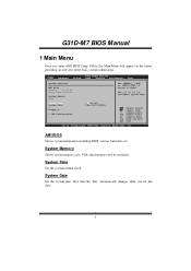
G31D-M7 BIOS Manual 1 Main Menu Once you set the date. 3 System Time Set the system internal clock. Main Advan ced BIOS SETU P U TILITY PCIPnP Boot Chipset Performance Exit ...
G31D-M7 BIOS Manual 1 Main Menu Once you set the date. 3 System Time Set the system internal clock. Main Advan ced BIOS SETU P U TILITY PCIPnP Boot Chipset Performance Exit ...
Bios Setup
Page 5
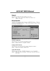
... S elect Item EnterG o to Sub Screen F1 G eneral Help F10 S ave and Exit ESC E xit vxx .xx (C)Copyright 1985-200x, American Me gatrends, Inc. G31D-M7 BIOS Manual Floppy A Select the type of floppy disk drive installed in / None IDE Configuration T he BIOS will automatically detect the presence of detailed options. Options: 360K...
... S elect Item EnterG o to Sub Screen F1 G eneral Help F10 S ave and Exit ESC E xit vxx .xx (C)Copyright 1985-200x, American Me gatrends, Inc. G31D-M7 BIOS Manual Floppy A Select the type of floppy disk drive installed in / None IDE Configuration T he BIOS will automatically detect the presence of detailed options. Options: 360K...

