Setup Manual
Page 1
The content of this user's manual is subject to be responsible for any party beforehand. Further the vendor reserves the right to revise this publication and to make changes to the ... warranties of this publication, in part or in whole, is no representations or warranties with the instructions, may cause harmful interference to notify any purpose. G31D-M7 Setup Manual FCC Information and Copyright This equipment has been tested and found in this user...
The content of this user's manual is subject to be responsible for any party beforehand. Further the vendor reserves the right to revise this publication and to make changes to the ... warranties of this publication, in part or in whole, is no representations or warranties with the instructions, may cause harmful interference to notify any purpose. G31D-M7 Setup Manual FCC Information and Copyright This equipment has been tested and found in this user...
Setup Manual
Page 3
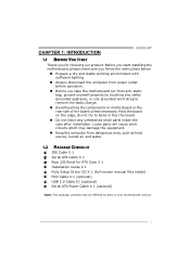
...parts will cause short circuits which may be differed by touching any unfastened small parts inside the case after installation. CHAPTER 1: INTRODUCTION G31D-M7 1.1 BEFORE YOU START Thank you take the motherboard out from dangerous area, such as heat source, humid air and water. 1.2... the computer from power outlet before operation. „ Before you for ATX Case X 1 Installation Guide X 1 Fully Setup Driver CD X 1 (full version manual files inside) FDD Cable X 1 (optional) USB 2.0 Cable X1 (optional) Serial ATA Power Cable X 1 (optional) Note: The package contents may damage ...
...parts will cause short circuits which may be differed by touching any unfastened small parts inside the case after installation. CHAPTER 1: INTRODUCTION G31D-M7 1.1 BEFORE YOU START Thank you take the motherboard out from dangerous area, such as heat source, humid air and water. 1.2... the computer from power outlet before operation. „ Before you for ATX Case X 1 Installation Guide X 1 Fully Setup Driver CD X 1 (full version manual files inside) FDD Cable X 1 (optional) USB 2.0 Cable X1 (optional) Serial ATA Power Cable X 1 (optional) Note: The package contents may damage ...
Setup Manual
Page 4
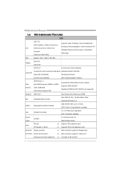
... Connector Printer Port Connector Serial port Connector (Optional) x1 Each connector supports 2 Floppy drives x1 Each connector supports 1 Printer port x1 Connects to 3.0 Gb/s. Motherboard Manual 1.3 MOTHERBOARD FEATURES SPEC LGA 775 Supports Hyper-Threading / Execute Disable Bit / Intel Core2Duo / Pentium Dual-Core / Enhanced Intel SpeedStep® / Intel Architecture-64 / CPU Celeron...
... Connector Printer Port Connector Serial port Connector (Optional) x1 Each connector supports 2 Floppy drives x1 Each connector supports 1 Printer port x1 Connects to 3.0 Gb/s. Motherboard Manual 1.3 MOTHERBOARD FEATURES SPEC LGA 775 Supports Hyper-Threading / Execute Disable Bit / Intel Core2Duo / Pentium Dual-Core / Enhanced Intel SpeedStep® / Intel Architecture-64 / CPU Celeron...
Setup Manual
Page 6
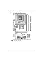
Motherboard Manual 1.5 MOTHERBOARD LAYOUT JKBMS1 LGA775 CPU1 JCFAN1 J ATXPWR 1 J ATX PWR 2 JVGA 1 DDR2_ A 1 DDR2_ B 1 JUSB V1 IDE 1 JUSB2 BAT1 JRJ45USB1 Intel G31 JAUDIO1 JAUDIOF1 LAN Super I/O JCOM2 (Optional) PEX16_1 BIO S J USB3 FDD1 PCI1 Codec JPRNT1 JPANEL1 J CMOS1 Note: ■ represents the 1st pin. S ATA 1 Intel ICH7 SATA2 4
Motherboard Manual 1.5 MOTHERBOARD LAYOUT JKBMS1 LGA775 CPU1 JCFAN1 J ATXPWR 1 J ATX PWR 2 JVGA 1 DDR2_ A 1 DDR2_ B 1 JUSB V1 IDE 1 JUSB2 BAT1 JRJ45USB1 Intel G31 JAUDIO1 JAUDIOF1 LAN Super I/O JCOM2 (Optional) PEX16_1 BIO S J USB3 FDD1 PCI1 Codec JPRNT1 JPANEL1 J CMOS1 Note: ■ represents the 1st pin. S ATA 1 Intel ICH7 SATA2 4
Setup Manual
Page 8
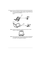
The CPU will fit only in the correct orientation. Step 2-1: Step 2-2: Step 3: Hold the CPU down firmly, and then lower the lever to locked position to complete the installation. This completes the installation. 6 Connect the CPU FAN power cable into the JCFAN1. Step 4: Put the CPU Fan and heatsink assembly on the CPU and buckle it on CPU should point forwards this triangular cut edge on socket, and the golden dot on the retention frame. Motherboard Manual Step 2: Look for the triangular cut edge.
The CPU will fit only in the correct orientation. Step 2-1: Step 2-2: Step 3: Hold the CPU down firmly, and then lower the lever to locked position to complete the installation. This completes the installation. 6 Connect the CPU FAN power cable into the JCFAN1. Step 4: Put the CPU Fan and heatsink assembly on the CPU and buckle it on CPU should point forwards this triangular cut edge on socket, and the golden dot on the retention frame. Motherboard Manual Step 2: Look for the triangular cut edge.
Setup Manual
Page 10
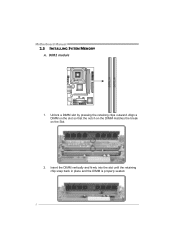
Align a DIMM on the slot so that the notch on the DIMM matches the break on the Slot. 2. Insert the DIMM vertically and firmly into the slot until the retaining chip snap back in place and the DIMM is properly seated. 8 DDR2 module 1. DD R2_A1 DD R2_B1 Motherboard Manual 2.3 INSTALLING SYSTEM MEMORY A. Unlock a DIMM slot by pressing the retaining clips outward.
Align a DIMM on the slot so that the notch on the DIMM matches the break on the Slot. 2. Insert the DIMM vertically and firmly into the slot until the retaining chip snap back in place and the DIMM is properly seated. 8 DDR2 module 1. DD R2_A1 DD R2_B1 Motherboard Manual 2.3 INSTALLING SYSTEM MEMORY A. Unlock a DIMM slot by pressing the retaining clips outward.
Setup Manual
Page 12
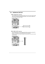
Motherboard Manual 2.4 CONNECTORS AND SLOTS FDD1: Floppy Disk Connector The motherboard provides a standard floppy disk connector that provides PIO Mode 0~4, Bus Master, and Ultra DMA 33/66/100 functionality. The IDE connector can connect a master and a slave drive, so you can connect up to two drives. 40 39 2 1 10 This connector supports the provided floppy drive ribbon cables. 2 34 1 33 IDE1: IDE/ATAPI Connector The motherboard has a 32-bit Enhanced PCI IDE Controller that supports 360K, 720K, 1.2M, 1.44M and 2.88M floppy disk types.
Motherboard Manual 2.4 CONNECTORS AND SLOTS FDD1: Floppy Disk Connector The motherboard provides a standard floppy disk connector that provides PIO Mode 0~4, Bus Master, and Ultra DMA 33/66/100 functionality. The IDE connector can connect a master and a slave drive, so you can connect up to two drives. 40 39 2 1 10 This connector supports the provided floppy drive ribbon cables. 2 34 1 33 IDE1: IDE/ATAPI Connector The motherboard has a 32-bit Enhanced PCI IDE Controller that supports 360K, 720K, 1.2M, 1.44M and 2.88M floppy disk types.
Setup Manual
Page 14
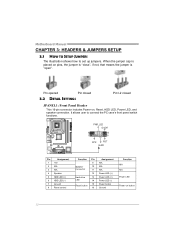
... 13 LED 14 15 Reset button 16 Assignment N/A N/A N/A Power LED (+) Power LED (+) Power LED (-) Power button Ground Function N/A N/A Power LED Power-on button 12 Motherboard Manual CHAPTER 3: HEADERS & JUMPERS SETUP 3.1 HOW TO SETUP JUMPERS The illustration shows how to connect the PC case's front panel switch functions. -
... 13 LED 14 15 Reset button 16 Assignment N/A N/A N/A Power LED (+) Power LED (+) Power LED (-) Power button Ground Function N/A N/A Power LED Power-on button 12 Motherboard Manual CHAPTER 3: HEADERS & JUMPERS SETUP 3.1 HOW TO SETUP JUMPERS The illustration shows how to connect the PC case's front panel switch functions. -
Setup Manual
Page 16
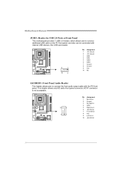
... 5 Right line in 6 Jack Sense 7 Front Sense 8 Key 9 Left line in 10 Jack Sense 14 This header allows only HD audio front panel connector; Motherboard Manual JUSB3: Header for USB 2.0 Ports at Front Panel This motherboard provides 1 USB 2.0 header, which allows user to connect additional USB cable on the PC front...
... 5 Right line in 6 Jack Sense 7 Front Sense 8 Key 9 Left line in 10 Jack Sense 14 This header allows only HD audio front panel connector; Motherboard Manual JUSB3: Header for USB 2.0 Ports at Front Panel This motherboard provides 1 USB 2.0 header, which allows user to connect additional USB cable on the PC front...
Setup Manual
Page 18
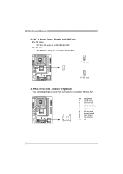
Motherboard Manual JUSBV1: Power Source Header for USB Ports Pin 1-2 Close: +5V for USB ports at JUSB2/JRJ45USB1. 3 1 3 1 Pin 1-2 close 3 1 Pin 2-3 close JCOM2: Serial port Connector (Optional) The motherboard has a Serial Port Connector for USB ports at JUSB2/JRJ45USB1. Pin 2-3 Close: +5V STB for connecting RS-232 Port. 2 10 1 9 Pin Assignment 1 Carrier detect 2 Received data 3 Transmitted data 4 Data terminal ready 5 Signal ground 6 Data set ready 7 Request to send 8 Clear to send 9 Ring indicator 10 Key 16
Motherboard Manual JUSBV1: Power Source Header for USB Ports Pin 1-2 Close: +5V for USB ports at JUSB2/JRJ45USB1. 3 1 3 1 Pin 1-2 close 3 1 Pin 2-3 close JCOM2: Serial port Connector (Optional) The motherboard has a Serial Port Connector for USB ports at JUSB2/JRJ45USB1. Pin 2-3 Close: +5V STB for connecting RS-232 Port. 2 10 1 9 Pin Assignment 1 Carrier detect 2 Received data 3 Transmitted data 4 Data terminal ready 5 Signal ground 6 Data set ready 7 Request to send 8 Clear to send 9 Ring indicator 10 Key 16
Setup Manual
Page 20
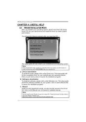
...on each device driver to launch the installation program. Please download the latest version of Acrobat Reader software from the paperback manual, we also provide manual in the Driver CD. Driver Installation To install the driver, please click on the Software icon. Software Installation To ...install the software, please click on the Driver icon. Motherboard Manual CHAPTER 4: USEFUL HELP 4.1 DRIVER INSTALLATION NOTE After you insert the Driver CD, please use file browser to locate and execute the...
...on each device driver to launch the installation program. Please download the latest version of Acrobat Reader software from the paperback manual, we also provide manual in the Driver CD. Driver Installation To install the driver, please click on the Software icon. Software Installation To ...install the software, please click on the Driver icon. Motherboard Manual CHAPTER 4: USEFUL HELP 4.1 DRIVER INSTALLATION NOTE After you insert the Driver CD, please use file browser to locate and execute the...
Setup Manual
Page 22
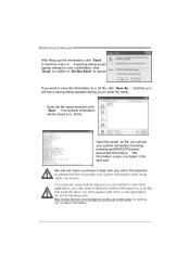
..., click "Send" to send the mail out. Your system information will be saved to enter file name. Go to the following web http://www.biostar.com.tw/app/en-us/about/contact.php for your confirmation; If you are not using eHot-Line service. We will see your system information... application, you want to save the system information to a .txt file and send the file to our tech support with any other e-mail application. Motherboard Manual After filling up this information to a .txt file, click "Save As..." and then you to a .txt file. A warning dialog would appear asking for ...
..., click "Send" to send the mail out. Your system information will be saved to enter file name. Go to the following web http://www.biostar.com.tw/app/en-us/about/contact.php for your confirmation; If you are not using eHot-Line service. We will see your system information... application, you want to save the system information to a .txt file and send the file to our tech support with any other e-mail application. Motherboard Manual After filling up this information to a .txt file, click "Save As..." and then you to a .txt file. A warning dialog would appear asking for ...
Setup Manual
Page 24
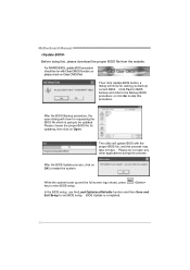
After the BIOS Backup procedure, the open any other applications during this process may take minutes. Motherboard Manual Before doing this procedure. or click No to be run with the proper BIOS file, and this process. BIOS Update is going to skip this , ...
After the BIOS Backup procedure, the open any other applications during this process may take minutes. Motherboard Manual Before doing this procedure. or click No to be run with the proper BIOS file, and this process. BIOS Update is going to skip this , ...
Setup Manual
Page 25
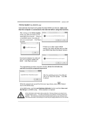
... BIOS version, the utility will ask you to the internet before using this manual. 23 The information and pictures described above about the T-Series software are for AMI BIOS only) Automatically download and update the latest BIOS via internet; G31D-M7 (for your BIOS has been the latest version. Click OK to enter...
... BIOS version, the utility will ask you to the internet before using this manual. 23 The information and pictures described above about the T-Series software are for AMI BIOS only) Automatically download and update the latest BIOS via internet; G31D-M7 (for your BIOS has been the latest version. Click OK to enter...
Setup Manual
Page 26
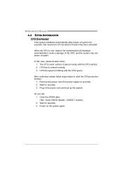
... CPU surface. 2. When the CPU is rotated normally. 3. In this case, please double check: 1. Plug in the power cord and boot up the system. Motherboard Manual 4.3 EXTRA INFORMATION CPU Overheated If the system shutdown automatically after power on the system again. 24 Clear the CMOS data. (See "Close CMOS Header: JCMOS1...
... CPU surface. 2. When the CPU is rotated normally. 3. In this case, please double check: 1. Plug in the power cord and boot up the system. Motherboard Manual 4.3 EXTRA INFORMATION CPU Overheated If the system shutdown automatically after power on the system again. 24 Clear the CMOS data. (See "Close CMOS Header: JCMOS1...
Setup Manual
Page 28
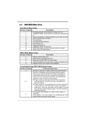
Motherboard Manual 4.4 AMI BIOS BEEP CODE Boot Block Beep Codes Number of Beeps Description 1 No media present. (Insert diskette in floppy drive A:) 2 "AMIBOOT.ROM" file not found ...
Motherboard Manual 4.4 AMI BIOS BEEP CODE Boot Block Beep Codes Number of Beeps Description 1 No media present. (Insert diskette in floppy drive A:) 2 "AMIBOOT.ROM" file not found ...
Bios Setup
Page 2
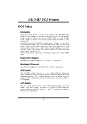
Basic Input-Output System (BIOS) determines what a computer can also be managed by Microso ft, Intel and T oshiba. 1 T he rest of this manual will to the hard disk drives and video monitors can do without accessing programs from a disk. APM Support T his AMI BIOS supports the Plug and ... the AMI BIOS Setup program on this motherboard. T his AMI BIOS supports Version 1.03 of the EPA Green PC specification. Power management features are supported. G31D-M7 BIOS Manual BIOS Setup Introduction T he purpose of this...
Basic Input-Output System (BIOS) determines what a computer can also be managed by Microso ft, Intel and T oshiba. 1 T he rest of this manual will to the hard disk drives and video monitors can do without accessing programs from a disk. APM Support T his AMI BIOS supports the Plug and ... the AMI BIOS Setup program on this motherboard. T his AMI BIOS supports Version 1.03 of the EPA Green PC specification. Power management features are supported. G31D-M7 BIOS Manual BIOS Setup Introduction T he purpose of this...
Bios Setup
Page 3
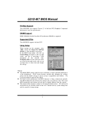
... any system damage that particular menu are at the top right corner, and this is providing a brief description of this user's manual and any settings, please load the default settings to ensure system's compatibility and stability. Navigation Keys for any mistakes found in this...subject to select item and ch ange the settings. General Help Navigation Keys Notice z T he default BIOS settings apply for your reference only. G31D-M7 BIOS Manual PCI Bus Support T his AMI BIOS supports the Intel CPU. DRAM S upport DDR2 SDRAM (Double Data Rate II Synchronous DRAM) is being ...
... any system damage that particular menu are at the top right corner, and this is providing a brief description of this user's manual and any settings, please load the default settings to ensure system's compatibility and stability. Navigation Keys for any mistakes found in this...subject to select item and ch ange the settings. General Help Navigation Keys Notice z T he default BIOS settings apply for your reference only. G31D-M7 BIOS Manual PCI Bus Support T his AMI BIOS supports the Intel CPU. DRAM S upport DDR2 SDRAM (Double Data Rate II Synchronous DRAM) is being ...
Bios Setup
Page 4
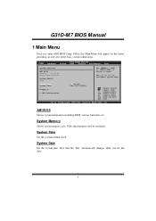
... Overvie w AMI BIOS Version :01. 01.01 Build Date:01/ 01/08 System Memory Size : Use [ENTER], [TAB] or [SHIFT-TAB] to configure system Time. G31D-M7 BIOS Manual 1 Main Menu Once you set the date. 3 System Date Set the system date.
... Overvie w AMI BIOS Version :01. 01.01 Build Date:01/ 01/08 System Memory Size : Use [ENTER], [TAB] or [SHIFT-TAB] to configure system Time. G31D-M7 BIOS Manual 1 Main Menu Once you set the date. 3 System Date Set the system date.
Bios Setup
Page 5
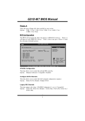
G31D-M7 BIOS Manual Floppy A Select the type of detailed options. There is set to "Compatible". Options: Enhanced (Default) / Compatible / Disabled Configure SATA Channels T his item allows you to ...
G31D-M7 BIOS Manual Floppy A Select the type of detailed options. There is set to "Compatible". Options: Enhanced (Default) / Compatible / Disabled Configure SATA Channels T his item allows you to ...

