Service Guide
Page 7
Table of Contents System Specifications 1 Features 1 System Block Diagram 5 Your Acer Notebook tour 6 Front View 6 Closed Front View 7 Left View 7 Right View 8 Bottom View 9 Indicators 9 TouchPad Basics 10 Using the Keyboard ... 21 Aspire 5741/5741G BIOS 22 Information 22 Main 23 Security 24 Boot 27 Exit 28 BIOS Flash Utilities 29 DOS Flash Utility 30 WinFlash Utility 32 Remove HDD/BIOS Password Utilities 33 Machine Disassembly and Replacement 39 Disassembly Requirements 39 Pre-disassembly Instructions 40 Disassembly Process 41 External Module Disassembly Process ...
Table of Contents System Specifications 1 Features 1 System Block Diagram 5 Your Acer Notebook tour 6 Front View 6 Closed Front View 7 Left View 7 Right View 8 Bottom View 9 Indicators 9 TouchPad Basics 10 Using the Keyboard ... 21 Aspire 5741/5741G BIOS 22 Information 22 Main 23 Security 24 Boot 27 Exit 28 BIOS Flash Utilities 29 DOS Flash Utility 30 WinFlash Utility 32 Remove HDD/BIOS Password Utilities 33 Machine Disassembly and Replacement 39 Disassembly Requirements 39 Pre-disassembly Instructions 40 Disassembly Process 41 External Module Disassembly Process ...
Service Guide
Page 8
... USB Board 69 Removing the Bluetooth Board 70 Removing the Mainboard 71 Removing the Thermal Module 75 Removing the CPU 77 LCD Module Disassembly Process 78 LCD Module Disassembly Flowchart 78 Removing the LCD Assembly 79 Removing the LCD Bezel 82 Removing the Camera Module 83 Removing the LCD Panel 84 Removing...
... USB Board 69 Removing the Bluetooth Board 70 Removing the Mainboard 71 Removing the Thermal Module 75 Removing the CPU 77 LCD Module Disassembly Process 78 LCD Module Disassembly Flowchart 78 Removing the LCD Assembly 79 Removing the LCD Bezel 82 Removing the Camera Module 83 Removing the LCD Panel 84 Removing...

Service Guide
Page 49
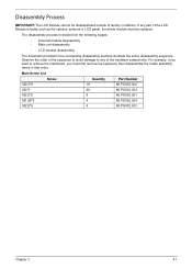
...on how to avoid mismatch when putting back the components. Chapter 3 Machine Disassembly and Replacement IMPORTANT: The outside housing and color may vary from the mass produced model. Disassembly Requirements To disassemble the computer, you need the following tools: • Wrist grounding strap and...8226; Plastic flat screwdriver • Plastic tweezers NOTE: The screws for maintenance and troubleshooting. Chapter 3 39 During the disassembly process, group the screws with the corresponding components to disassemble the notebook computer for the different components vary in size.
...on how to avoid mismatch when putting back the components. Chapter 3 Machine Disassembly and Replacement IMPORTANT: The outside housing and color may vary from the mass produced model. Disassembly Requirements To disassemble the computer, you need the following tools: • Wrist grounding strap and...8226; Plastic flat screwdriver • Plastic tweezers NOTE: The screws for maintenance and troubleshooting. Chapter 3 39 During the disassembly process, group the screws with the corresponding components to disassemble the notebook computer for the different components vary in size.

Service Guide
Page 50
Pre-disassembly Instructions Before proceeding with the disassembly procedure, make sure that you do the following: 1. Place the system on a flat, stable surface. 4. Unplug the AC adapter and all peripherals. 2. Remove the battery pack. 40 Chapter 3 Turn off the power to the system and all power and signal cables from the system. 3.
Pre-disassembly Instructions Before proceeding with the disassembly procedure, make sure that you do the following: 1. Place the system on a flat, stable surface. 4. Unplug the AC adapter and all peripherals. 2. Remove the battery pack. 40 Chapter 3 Turn off the power to the system and all power and signal cables from the system. 3.
Service Guide
Page 51
...002 M2*3 26 86.PSV02.004 M2.5*5 8 86.PSV02.001 M1.98*3 4 86.PSV02.004 M2.5*6 4 86.PSV02.003 Chapter 3 41 The disassembly process is faulty, such as the camera, antenna or LCD panel, the whole module must first remove the keyboard, then... disassemble the inside assembly frame in the succeeding disassembly sections illustrate the entire disassembly sequence. For example, if you must be disassembled outside of the LCD Module is divided into the following stages: • External module...
...002 M2*3 26 86.PSV02.004 M2.5*5 8 86.PSV02.001 M1.98*3 4 86.PSV02.004 M2.5*6 4 86.PSV02.003 Chapter 3 41 The disassembly process is faulty, such as the camera, antenna or LCD panel, the whole module must first remove the keyboard, then... disassemble the inside assembly frame in the succeeding disassembly sections illustrate the entire disassembly sequence. For example, if you must be disassembled outside of the LCD Module is divided into the following stages: • External module...
Service Guide
Page 52
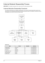
... that need to be removed during servicing. Turn off system and peripherals power Disconnect power and signal cables from the mass produced model. External Module Disassembly Process IMPORTANT: The outside housing and color may vary from system Remove Battery Remove Dummy Card Remove HDD/WLAN/DIM M Door Remove 3G Cover Remove...*3 Quantity 1 2 1 2 1 4 Part No. 86.PSV02.002 86.PSV02.004 86.PSV02.002 86.PSV02.002 86.PSV02.004 86.PSV02.004 42 Chapter 3 External Modules Disassembly Flowchart The flowchart below gives you a graphic representation of the external module...
... that need to be removed during servicing. Turn off system and peripherals power Disconnect power and signal cables from the mass produced model. External Module Disassembly Process IMPORTANT: The outside housing and color may vary from system Remove Battery Remove Dummy Card Remove HDD/WLAN/DIM M Door Remove 3G Cover Remove...*3 Quantity 1 2 1 2 1 4 Part No. 86.PSV02.002 86.PSV02.004 86.PSV02.002 86.PSV02.002 86.PSV02.004 86.PSV02.004 42 Chapter 3 External Modules Disassembly Flowchart The flowchart below gives you a graphic representation of the external module...
Service Guide
Page 64
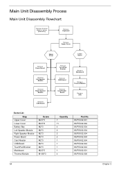
Main Unit Disassembly Process Main Unit Disassembly Flowchart Remove External Modules before proceeding Remove Keyboard Remove Upper Cover Upper Cover Lower Cover Remove Power Board Remove Left Speaker Module Remove Right Speaker ...
Main Unit Disassembly Process Main Unit Disassembly Flowchart Remove External Modules before proceeding Remove Keyboard Remove Upper Cover Upper Cover Lower Cover Remove Power Board Remove Left Speaker Module Remove Right Speaker ...

Service Guide
Page 67
Remove the eleven (11) screws on page 42. 2. See "External Module Disassembly Process" on the lower cover and four (4) screws from the battery bay. Turn the computer over. Step Upper Cover (red callout) Size M2.5*8 Battery Bay (green callout) M2*3 Quantity 11 4 Screw Type Chapter 3 57 Removing the Upper Cover 1.
Remove the eleven (11) screws on page 42. 2. See "External Module Disassembly Process" on the lower cover and four (4) screws from the battery bay. Turn the computer over. Step Upper Cover (red callout) Size M2.5*8 Battery Bay (green callout) M2*3 Quantity 11 4 Screw Type Chapter 3 57 Removing the Upper Cover 1.

Service Guide
Page 88
LCD Module Disassembly Process LCD Module Disassembly Flowchart Remove LCD Assembly Remove LCD Bezel Remove Camera Module Remove LCD Panel Remove LCD Brackets and FPC Cable Remove Antennas Remove Microphone Cable Screw List Step LCD Assy LCD Bezel LCD Panel LCD Brackets Screw M2.5*8 M2.5*6 M2.5*6 M2*3 Quantity 4 2 2 6 Part No. 86.PSV02.002 86.PSV02.003 86.PSV02.003 86.PSV02.004 78 Chapter 3
LCD Module Disassembly Process LCD Module Disassembly Flowchart Remove LCD Assembly Remove LCD Bezel Remove Camera Module Remove LCD Panel Remove LCD Brackets and FPC Cable Remove Antennas Remove Microphone Cable Screw List Step LCD Assy LCD Bezel LCD Panel LCD Brackets Screw M2.5*8 M2.5*6 M2.5*6 M2*3 Quantity 4 2 2 6 Part No. 86.PSV02.002 86.PSV02.003 86.PSV02.003 86.PSV02.004 78 Chapter 3
Service Guide
Page 141
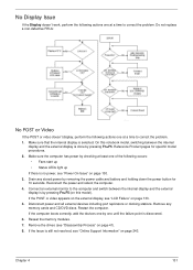
..., perform the following actions one at a time to correct the problem. On this model). If the POST or video appears on the external display, see "Disassembly Process" on page 133. 5. If the computer boots correctly, add the devices one by pressing Fn+F5. Connect an external monitor to the computer and...
..., perform the following actions one at a time to correct the problem. On this model). If the POST or video appears on the external display, see "Disassembly Process" on page 133. 5. If the computer boots correctly, add the devices one by pressing Fn+F5. Connect an external monitor to the computer and...
Service Guide
Page 142
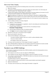
.../horizontal lines or dark spots display in the application. If desktop display resolution is listed under Other Devices. 9. Remove and reinstall the video driver. 8. See "Disassembly Process" on page 41. 4. Readjust if necessary. 6. Click and drag the Resolution slider to the desired resolution. e. Check the Device Manager to determine that the... should be replaced. 5. Abnormal Video Display If video displays abnormally, perform the following actions one at a time to correct the problem. 1. Reboot the computer. 2. b. See "Disassembly Process" on page 41. 5.
.../horizontal lines or dark spots display in the application. If desktop display resolution is listed under Other Devices. 9. Remove and reinstall the video driver. 8. See "Disassembly Process" on page 41. 4. Readjust if necessary. 6. Click and drag the Resolution slider to the desired resolution. e. Check the Device Manager to determine that the... should be replaced. 5. Abnormal Video Display If video displays abnormally, perform the following actions one at a time to correct the problem. 1. Reboot the computer. 2. b. See "Disassembly Process" on page 41. 5.
Service Guide
Page 146
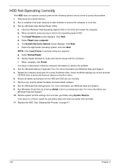
... earlier time and date. 11. Select Repair your computer. For more information see Windows Help and Support. 5. Run the Windows Vista Startup Repair Utility: a. See "Disassembly Process" on page 41. 136 Chapter 4 f. HDD Not Operating Correctly If the HDD does not operate correctly, perform the following actions one at a time to...
... earlier time and date. 11. Select Repair your computer. For more information see Windows Help and Support. 5. Run the Windows Vista Startup Repair Utility: a. See "Disassembly Process" on page 41. 136 Chapter 4 f. HDD Not Operating Correctly If the HDD does not operate correctly, perform the following actions one at a time to...
Service Guide
Page 149
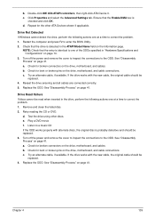
... the entry is probably defective and should be read when inserted in the ATAPI Model Name field on the drive, motherboard, and cables. See "Disassembly Process" on page 41. b. Try an alternate cable, if available. Turn off the power and remove the cover to inspect the connections to...to a music CD If the ODD works properly with the new cable, the original cable should be replaced. 4. Retry reading the CD or DVD. See "Disassembly Process" on page 41. b. a. Check for the other discs. If the drive works with the new cable, the original cable should be replaced. 4. ...
... the entry is probably defective and should be read when inserted in the ATAPI Model Name field on the drive, motherboard, and cables. See "Disassembly Process" on page 41. b. Try an alternate cable, if available. Turn off the power and remove the cover to inspect the connections to...to a music CD If the ODD works properly with the new cable, the original cable should be replaced. 4. Retry reading the CD or DVD. See "Disassembly Process" on page 41. b. a. Check for the other discs. If the drive works with the new cable, the original cable should be replaced. 4. ...
Service Guide
Page 255
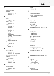
... Common Problems 130 computer on indicator 9 CPU Removing 77 Replacing 104 D DIMM Modules Replacing 123 Display 5 Index display hotkeys 13 E EasyTouch Failure 140 External Module Disassembly Flowchart 42 F Features 1 Flash Utility 29 FPC Cable Removing 86 FRU (Field Replaceable Unit) List 155 H Hard Disk Drive Removing 52 Replacing 121 HDTV Switch...
... Common Problems 130 computer on indicator 9 CPU Removing 77 Replacing 104 D DIMM Modules Replacing 123 Display 5 Index display hotkeys 13 E EasyTouch Failure 140 External Module Disassembly Flowchart 42 F Features 1 Flash Utility 29 FPC Cable Removing 86 FRU (Field Replaceable Unit) List 155 H Hard Disk Drive Removing 52 Replacing 121 HDTV Switch...

Service Guide
Page 256
... 78 LCD Module Reassembly Procedure 93 LCD Panel Removing 84 Replacing 95 Left Speaker Module Removing 61 Replacing 116 M Main Unit Disassembly Flowchart 54 Mainboard Removing 68, 69, 70, 71 Replacing 106 media access on indicator 9 Memory Replacing 123 Memory Check 130 Model Definition 170 N No Display ...
... 78 LCD Module Reassembly Procedure 93 LCD Panel Removing 84 Replacing 95 Left Speaker Module Removing 61 Replacing 116 M Main Unit Disassembly Flowchart 54 Mainboard Removing 68, 69, 70, 71 Replacing 106 media access on indicator 9 Memory Replacing 123 Memory Check 130 Model Definition 170 N No Display ...


