
Service Guide
Page 5
...FEATURES will not be covered in the printed Service Guide. This Service Guide provides you with further technical details. 2. In such cases, please contact your regional offices or the responsible personnel/channel to provide you should check the most up-to-date information available on...decided to those given in the FRU list of customer machines. You MUST use the list provided by your regional web or channel. For ACER-AUTHORIZED SERVICE PROVIDERS, your regional office MAY have a DIFFERENT part number code to extend the functionality of a machine (e.g. Please note WHEN...
...FEATURES will not be covered in the printed Service Guide. This Service Guide provides you with further technical details. 2. In such cases, please contact your regional offices or the responsible personnel/channel to provide you should check the most up-to-date information available on...decided to those given in the FRU list of customer machines. You MUST use the list provided by your regional web or channel. For ACER-AUTHORIZED SERVICE PROVIDERS, your regional office MAY have a DIFFERENT part number code to extend the functionality of a machine (e.g. Please note WHEN...
Service Guide
Page 35
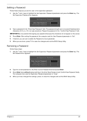
... Password fields. If desired, you set the user or the supervisor password: 1. Removing a Password Follow these steps as you can not exceed 8 alphanumeric characters (A-Z, a-z, 0-9, not case sensitive). After setting the password, the computer sets the User Password parameter to highlight the Set Supervisor Password parameter and press the Enter key. Press...
... Password fields. If desired, you set the user or the supervisor password: 1. Removing a Password Follow these steps as you can not exceed 8 alphanumeric characters (A-Z, a-z, 0-9, not case sensitive). After setting the password, the computer sets the User Password parameter to highlight the Set Supervisor Password parameter and press the Enter key. Press...

Service Guide
Page 70
Remove the seven (7) screws on the Upper Cover as shown, then lift the Upper Cover clear of the Lower Cover. 60 Chapter 3 Work along the front edge of the cover, pry apart the Upper and Lower Covers as shown. Step Upper Cover Size M2.5*5 Quantity 7 Screw Type 10. Starting at the top right side of the casing to the left as shown. 9.
Remove the seven (7) screws on the Upper Cover as shown, then lift the Upper Cover clear of the Lower Cover. 60 Chapter 3 Work along the front edge of the cover, pry apart the Upper and Lower Covers as shown. Step Upper Cover Size M2.5*5 Quantity 7 Screw Type 10. Starting at the top right side of the casing to the left as shown. 9.
Service Guide
Page 82
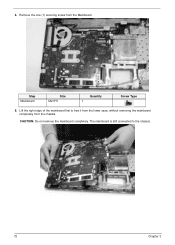
The mainboard is still connected to free it from the lower case, without removing the mainboard completely from the Mainboard. Step Mainboard Size M2.5*5 Quantity 1 Screw Type 5. CAUTION: Do not remove the mainboard completely. 4. Lift the right edge of the mainboard first to the chassis. 72 Chapter 3 Remove the one (1) securing screw from the chassis.
The mainboard is still connected to free it from the lower case, without removing the mainboard completely from the Mainboard. Step Mainboard Size M2.5*5 Quantity 1 Screw Type 5. CAUTION: Do not remove the mainboard completely. 4. Lift the right edge of the mainboard first to the chassis. 72 Chapter 3 Remove the one (1) securing screw from the chassis.
Service Guide
Page 116
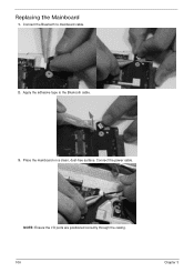
Connect the Bluetooth to the Bluetooth cable. 3. Connect the power cable. Replacing the Mainboard 1. Apply the adhesive tape to mainboard cable. 2. NOTE: Ensure the I/O ports are positioned correctly through the casing. 106 Chapter 3 Place the mainboard on a clean, dust-free surface.
Connect the Bluetooth to the Bluetooth cable. 3. Connect the power cable. Replacing the Mainboard 1. Apply the adhesive tape to mainboard cable. 2. NOTE: Ensure the I/O ports are positioned correctly through the casing. 106 Chapter 3 Place the mainboard on a clean, dust-free surface.
Service Guide
Page 136
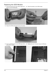
flush with the two (2) screws. 4. secure it is 5. Push the ODD Module into the tray, bottom edge first, to the ODD Module. 3. Replacing the ODD Module 1. Press the bezel into the ODD bay until it to 2. Replace the one (1) screw to secure the Module. Secure the ODD bracket with the casing. 126 Chapter 3 Place the bracket on the ODD module.
flush with the two (2) screws. 4. secure it is 5. Push the ODD Module into the tray, bottom edge first, to the ODD Module. 3. Replacing the ODD Module 1. Press the bezel into the ODD bay until it to 2. Replace the one (1) screw to secure the Module. Secure the ODD bracket with the casing. 126 Chapter 3 Place the bracket on the ODD module.
Service Guide
Page 137
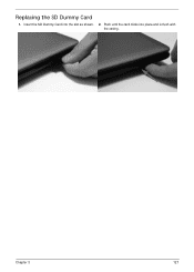
Replacing the SD Dummy Card 1. Insert the SD Dummy Card into place and is flush with the casing. Chapter 3 127 Push until the card clicks into the slot as shown. 2.
Replacing the SD Dummy Card 1. Insert the SD Dummy Card into place and is flush with the casing. Chapter 3 127 Push until the card clicks into the slot as shown. 2.
Service Guide
Page 140
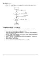
... Intermittently If the system powers off at intervals, perform the following actions one at a time to correct the problem. 1. Disconnect the power and open the casing to the computer and the electrical outlet. 2. Remove any surge protectors between the computer and the outlet. 3. Remove any extension cables between the computer and...
... Intermittently If the system powers off at intervals, perform the following actions one at a time to correct the problem. 1. Disconnect the power and open the casing to the computer and the electrical outlet. 2. Remove any surge protectors between the computer and the outlet. 3. Remove any extension cables between the computer and...

Service Guide
Page 171
CATEGORY Acer Description POWER CORD US 3 PIN POWER CORD EU 3 PIN POWER CORD AUS 3 PIN POWER CORD UK 3 PIN POWER CORD CHINA 3 PIN POWER CORD SWISS 3 PIN ... POWER CORD KOREA 3 PIN POWER CORD ISRAEL 3 PIN POWER CORD INDIA 3 PIN POWER CORD TWN 3 PIN POWER CORD ARGENTINA 3 PIN CASE/COVER/BRACKET ASSEMBLY UPPER CASE ASSY, INCL. TP/TP MYLAR LOWER CASE LOGIC LOWER DOOR 3G DOOR TP BRACKET HDD CARRIER AcerPN 27.TAVV5.001 27.TAVV5.002 27.TAVV5.003 27...
CATEGORY Acer Description POWER CORD US 3 PIN POWER CORD EU 3 PIN POWER CORD AUS 3 PIN POWER CORD UK 3 PIN POWER CORD CHINA 3 PIN POWER CORD SWISS 3 PIN ... POWER CORD KOREA 3 PIN POWER CORD ISRAEL 3 PIN POWER CORD INDIA 3 PIN POWER CORD TWN 3 PIN POWER CORD ARGENTINA 3 PIN CASE/COVER/BRACKET ASSEMBLY UPPER CASE ASSY, INCL. TP/TP MYLAR LOWER CASE LOGIC LOWER DOOR 3G DOOR TP BRACKET HDD CARRIER AcerPN 27.TAVV5.001 27.TAVV5.002 27.TAVV5.003 27...
Service Guide
Page 172
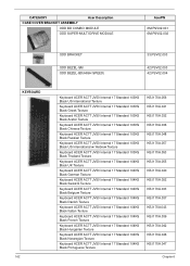
CATEGORY Acer Description CASE/COVER/BRACKET ASSEMBLY ODD BD COMBO MODULE ODD SUPER-MULTI DRIVE MODULE AcerPN 6M.PSV02.001 6M.PSV02.002 KEYBOARD 162 ODD BRACKET ODD BEZEL-SM ODD BEZEL-BD(HIGH SPEED) 33.PSV02.003 42.PSV02.003 42.PSV02.004 Keyboard ACER AC7T JV50 ...103KS Black US International w/ Hebrew Texture Keyboard ACER AC7T JV50 Internal 17 Standard 103KS Black Thailand Texture Keyboard ACER AC7T JV50 Internal 17 Standard 104KS Black UK Texture Keyboard ACER AC7T JV50 Internal 17 Standard 104KS Black German Texture Keyboard ACER AC7T JV50 Internal 17 Standard 104KS Black Swiss/G...
CATEGORY Acer Description CASE/COVER/BRACKET ASSEMBLY ODD BD COMBO MODULE ODD SUPER-MULTI DRIVE MODULE AcerPN 6M.PSV02.001 6M.PSV02.002 KEYBOARD 162 ODD BRACKET ODD BEZEL-SM ODD BEZEL-BD(HIGH SPEED) 33.PSV02.003 42.PSV02.003 42.PSV02.004 Keyboard ACER AC7T JV50 ...103KS Black US International w/ Hebrew Texture Keyboard ACER AC7T JV50 Internal 17 Standard 103KS Black Thailand Texture Keyboard ACER AC7T JV50 Internal 17 Standard 104KS Black UK Texture Keyboard ACER AC7T JV50 Internal 17 Standard 104KS Black German Texture Keyboard ACER AC7T JV50 Internal 17 Standard 104KS Black Swiss/G...


