Quick Start Guide
Page 7
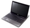
...functions like the and right) left and right mouse buttons. 9 Palmrest Comfortable support area for recording sound. 1. Charging: The light shows amber when the battery is closed up. Fully charged: The light shows blue when in AC mode. 8 Click buttons (left The left and right buttons function like a computer...PC depends on the model purchased. The front panel indicators are visible even when the computer cover is charging. 2. Battery1 Indicates the computer's battery status. 1. English 5 # Icon 3 Item HDD Description Indicates when the hard disk drive is active.
...functions like the and right) left and right mouse buttons. 9 Palmrest Comfortable support area for recording sound. 1. Charging: The light shows amber when the battery is closed up. Fully charged: The light shows blue when in AC mode. 8 Click buttons (left The left and right buttons function like a computer...PC depends on the model purchased. The front panel indicators are visible even when the computer cover is charging. 2. Battery1 Indicates the computer's battery status. 1. English 5 # Icon 3 Item HDD Description Indicates when the hard disk drive is active.

Quick Start Guide
Page 11
English 9 Base view 1 2 6 5 3 4 # Icon 1 2 3 4 5 6 Item Battery bay Battery release latch Hard disk bay Memory compartment Battery lock Description Houses the computer's battery pack. Houses the computer's hard disk (secured with screws). Houses the computer's main memory. Note: Do not cover or obstruct the opening of the fan. ...;C to 65 °C • Humidity (non-condensing): • Operating: 20% to 80% • Non-operating: 20% to stay cool, even after prolonged use. Releases the battery for removal. Locks the...
English 9 Base view 1 2 6 5 3 4 # Icon 1 2 3 4 5 6 Item Battery bay Battery release latch Hard disk bay Memory compartment Battery lock Description Houses the computer's battery pack. Houses the computer's hard disk (secured with screws). Houses the computer's main memory. Note: Do not cover or obstruct the opening of the fan. ...;C to 65 °C • Humidity (non-condensing): • Operating: 20% to 80% • Non-operating: 20% to stay cool, even after prolonged use. Releases the battery for removal. Locks the...
Service Guide
Page 7
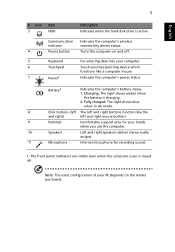
Table of Contents System Specifications 1 Features 1 System Block Diagram 5 Your Acer Notebook tour 6 Front View 6 Closed Front View 7 Left View 7 ...Specifications and Configurations 14 System Utilities 21 BIOS Setup Utility 21 Navigating the BIOS Utility 21 Aspire 5741/5741G BIOS 22 Information 22 Main 23 Security 24 Boot 27 Exit 28 BIOS Flash Utilities...40 Disassembly Process 41 External Module Disassembly Process 42 External Modules Disassembly Flowchart 42 Removing the Battery Pack 43 Removing the SD Dummy Card 44 Removing the Optical Drive Module 45 Removing the...
Table of Contents System Specifications 1 Features 1 System Block Diagram 5 Your Acer Notebook tour 6 Front View 6 Closed Front View 7 Left View 7 ...Specifications and Configurations 14 System Utilities 21 BIOS Setup Utility 21 Navigating the BIOS Utility 21 Aspire 5741/5741G BIOS 22 Information 22 Main 23 Security 24 Boot 27 Exit 28 BIOS Flash Utilities...40 Disassembly Process 41 External Module Disassembly Process 42 External Modules Disassembly Flowchart 42 Removing the Battery Pack 43 Removing the SD Dummy Card 44 Removing the Optical Drive Module 45 Removing the...
Service Guide
Page 8
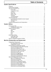
... 123 Replacing the 3G Cover 124 Replacing the Logic Lower Door 125 Replacing the ODD Module 126 Replacing the SD Dummy Card 127 Replacing the Battery 128 Troubleshooting 129 Common Problems 129 Power On Issue 130 No Display Issue 131 Random Loss of BIOS Settings 132 LCD Failure 133 Built-In...
... 123 Replacing the 3G Cover 124 Replacing the Logic Lower Door 125 Replacing the ODD Module 126 Replacing the SD Dummy Card 127 Replacing the Battery 128 Troubleshooting 129 Common Problems 129 Power On Issue 130 No Display Issue 131 Random Loss of BIOS Settings 132 LCD Failure 133 Built-In...
Service Guide
Page 13
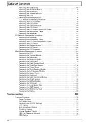
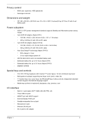
...(H) mm (15 x 9.9 x 0.98/1.3 inches)2.6 kg (5.74 lbs.)10 with 6-cell battery pack Power subsystem • ACPI 3.0 CPU power management standard: supports Standby and Hibernation power-saving modes • 3-pin 65 W AC adapter (Aspire 5741):· • 108 (W) x 46 (D) x 29.5 (H) mm (4.25 x 1.81...Acer QuicCharge™ technology (Aspire 5741G): • 80% charge in 1 hour· • 2-hour rapid charge system-off • 48.8 W 4400 mAh 6-cell Li-ion standard battery pack • Estimated battery life: up to 4.0 hours (Aspire 5741) • Estimated battery life: up to 3.0 hours (Aspire...
...(H) mm (15 x 9.9 x 0.98/1.3 inches)2.6 kg (5.74 lbs.)10 with 6-cell battery pack Power subsystem • ACPI 3.0 CPU power management standard: supports Standby and Hibernation power-saving modes • 3-pin 65 W AC adapter (Aspire 5741):· • 108 (W) x 46 (D) x 29.5 (H) mm (4.25 x 1.81...Acer QuicCharge™ technology (Aspire 5741G): • 80% charge in 1 hour· • 2-hour rapid charge system-off • 48.8 W 4400 mAh 6-cell Li-ion standard battery pack • Estimated battery life: up to 4.0 hours (Aspire 5741) • Estimated battery life: up to 3.0 hours (Aspire...
Service Guide
Page 14
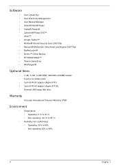
Software • Acer Crystal Eye • Acer eRecovery Management • Acer Backup Manager • Adobe® Flash® Player • Adobe® Reader® • Cyberlink® Power DVD™ • eSobi™ &#... WildTangent® Optional Items • 1 GB / 2 GB / 4 GB DDR3 1066 MHz soDIMM module • 6-cell Li-ion battery pack • 3-pin 65 W AC adapter (Aspire 5741) • 3-pin 90 W AC adapter (Aspire 5741G) • External USB floppy disk drive Warranty • One-year International Travelers Warranty (ITW) Environment • Temperature: • Operating...
Software • Acer Crystal Eye • Acer eRecovery Management • Acer Backup Manager • Adobe® Flash® Player • Adobe® Reader® • Cyberlink® Power DVD™ • eSobi™ &#... WildTangent® Optional Items • 1 GB / 2 GB / 4 GB DDR3 1066 MHz soDIMM module • 6-cell Li-ion battery pack • 3-pin 65 W AC adapter (Aspire 5741) • 3-pin 90 W AC adapter (Aspire 5741G) • External USB floppy disk drive Warranty • One-year International Travelers Warranty (ITW) Environment • Temperature: • Operating...
Service Guide
Page 17
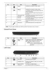
.... 1 Left View Icon Item Multi-in AC mode. The left and right buttons function like the left and right) Palmrest Speakers Microphone Indicates the computer's battery status. 1. No. 1 2 3 1 2 3 4 56 7 Icon Item DC-in jack Ventilation slots External display (VGA) port Description Connects to an AC adapter Enable the computer to stay...
.... 1 Left View Icon Item Multi-in AC mode. The left and right buttons function like the left and right) Palmrest Speakers Microphone Indicates the computer's battery status. 1. No. 1 2 3 1 2 3 4 56 7 Icon Item DC-in jack Ventilation slots External display (VGA) port Description Connects to an AC adapter Enable the computer to stay...
Service Guide
Page 19
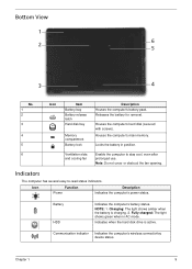
... Bottom View 1 2 6 5 3 4 No. 1 2 3 4 5 Icon Item Battery bay Battery release latch Hard disk bay Memory compartment Battery lock Description Houses the computer's battery pack. Battery HDD Indicates the computer's battery status. NOTE: 1. Indicates when the hard disk drive is charging. 2. Communication indicator Indicates the...computer's hard disk (secured with screws). Houses the computer's main memory. Charging: The light shows amber when the battery is active. Fully charged: The light shows green when in position. 6 Ventilation slots Enable the computer to -...
... Bottom View 1 2 6 5 3 4 No. 1 2 3 4 5 Icon Item Battery bay Battery release latch Hard disk bay Memory compartment Battery lock Description Houses the computer's battery pack. Battery HDD Indicates the computer's battery status. NOTE: 1. Indicates when the hard disk drive is charging. 2. Communication indicator Indicates the...computer's hard disk (secured with screws). Houses the computer's main memory. Charging: The light shows amber when the battery is active. Fully charged: The light shows green when in position. 6 Ventilation slots Enable the computer to -...
Service Guide
Page 39
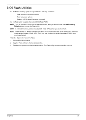
... required for the following conditions: • New versions of system programs • New features or options • Restore a BIOS when it becomes corrupted. If the battery pack does not contain enough power to run the Flash utility.
... required for the following conditions: • New versions of system programs • New features or options • Restore a BIOS when it becomes corrupted. If the battery pack does not contain enough power to run the Flash utility.

Service Guide
Page 50
Place the system on a flat, stable surface. 4. Pre-disassembly Instructions Before proceeding with the disassembly procedure, make sure that you do the following: 1. Unplug the AC adapter and all peripherals. 2. Turn off the power to the system and all power and signal cables from the system. 3. Remove the battery pack. 40 Chapter 3
Place the system on a flat, stable surface. 4. Pre-disassembly Instructions Before proceeding with the disassembly procedure, make sure that you do the following: 1. Unplug the AC adapter and all peripherals. 2. Turn off the power to the system and all power and signal cables from the system. 3. Remove the battery pack. 40 Chapter 3
Service Guide
Page 52
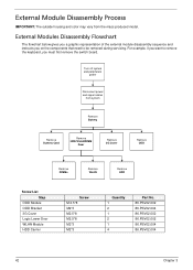
... Disconnect power and signal cables from the mass produced model. External Module Disassembly Process IMPORTANT: The outside housing and color may vary from system Remove Battery Remove Dummy Card Remove HDD/WLAN/DIM M Door Remove 3G Cover Remove ODD Remove DIMMs Remove WLAN Remove HDD Screw List Step ODD Module ODD...
... Disconnect power and signal cables from the mass produced model. External Module Disassembly Process IMPORTANT: The outside housing and color may vary from system Remove Battery Remove Dummy Card Remove HDD/WLAN/DIM M Door Remove 3G Cover Remove ODD Remove DIMMs Remove WLAN Remove HDD Screw List Step ODD Module ODD...

Service Guide
Page 53
Chapter 3 43 Slide the battery lock in the direction shown. 2. Slide and hold the battery release latch to the release position (1), then lift out the battery pack from the main unit (2). 2 1 NOTE: Please follow local regulations for disposal. Turn computer over. Removing the Battery Pack 1.
Chapter 3 43 Slide the battery lock in the direction shown. 2. Slide and hold the battery release latch to the release position (1), then lift out the battery pack from the main unit (2). 2 1 NOTE: Please follow local regulations for disposal. Turn computer over. Removing the Battery Pack 1.

Service Guide
Page 55
Remove the screw securing the ODD module. Pull the optical drive module out from the chassis. Step ODD Module Size M2.5*8 Quantity 1 3. Screw Type Chapter 3 45 Removing the Optical Drive Module 1. See "Removing the Battery Pack" on page 43. 2.
Remove the screw securing the ODD module. Pull the optical drive module out from the chassis. Step ODD Module Size M2.5*8 Quantity 1 3. Screw Type Chapter 3 45 Removing the Optical Drive Module 1. See "Removing the Battery Pack" on page 43. 2.
Service Guide
Page 64
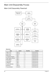
... Board Remove TouchPad Bracket Remove USB Board Remove Card Reader Board Remove Mainboard Remove Thermal Module Remove CPU Screw List Step Upper Cover Lower Cover Battery Bay Left Speaker Module Right Speaker Module Power Board Card Reader USB Board TouchPad Bracket Mainboard Thermal Module Screw M2.5*5 M2.5*8 M2*3 M2*3 M2*3 M2...
... Board Remove TouchPad Bracket Remove USB Board Remove Card Reader Board Remove Mainboard Remove Thermal Module Remove CPU Screw List Step Upper Cover Lower Cover Battery Bay Left Speaker Module Right Speaker Module Power Board Card Reader USB Board TouchPad Bracket Mainboard Thermal Module Screw M2.5*5 M2.5*8 M2*3 M2*3 M2*3 M2...

Service Guide
Page 67
Remove the eleven (11) screws on page 42. 2. Turn the computer over. Removing the Upper Cover 1. Step Upper Cover (red callout) Size M2.5*8 Battery Bay (green callout) M2*3 Quantity 11 4 Screw Type Chapter 3 57 See "External Module Disassembly Process" on the lower cover and four (4) screws from the battery bay.
Remove the eleven (11) screws on page 42. 2. Turn the computer over. Removing the Upper Cover 1. Step Upper Cover (red callout) Size M2.5*8 Battery Bay (green callout) M2*3 Quantity 11 4 Screw Type Chapter 3 57 See "External Module Disassembly Process" on the lower cover and four (4) screws from the battery bay.
Service Guide
Page 129
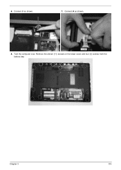
Chapter 3 119 Connect B as shown. 8. Remove the eleven (11) screws on the lower cover and four (4) screws from the battery bay. 6. Turn the computer over. Connect A as shown. 7.
Chapter 3 119 Connect B as shown. 8. Remove the eleven (11) screws on the lower cover and four (4) screws from the battery bay. 6. Turn the computer over. Connect A as shown. 7.

Service Guide
Page 138
Replacing the Battery 1. Slide and hold the battery release latch to secure the battery in the direction shown to the release position (1), insert the battery pack and press down (2). 2. Slide the battery lock in place. 2 1 128 Chapter 3
Replacing the Battery 1. Slide and hold the battery release latch to secure the battery in the direction shown to the release position (1), insert the battery pack and press down (2). 2. Slide the battery lock in place. 2 1 128 Chapter 3
Service Guide
Page 141
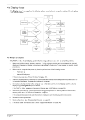
... devices including port replicators or docking stations. Restart the computer. If the computer boots correctly, add the devices one by removing the power cable and battery and holding down the power button for specific model procedures. 2. If the POST or video appears on the external display, see "Online Support Information" on...
... devices including port replicators or docking stations. Restart the computer. If the computer boots correctly, add the devices one by removing the power cable and battery and holding down the power button for specific model procedures. 2. If the POST or video appears on the external display, see "Online Support Information" on...
Service Guide
Page 142
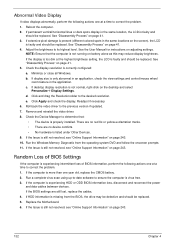
...is still not resolved, see "Online Support Information" on page 243. 10. If the Issue is more than one year old, replace the CMOS battery. 2. Roll back the video driver to the desired resolution. Replace the Motherboard. 6. See "Disassembly Process" on adjusting settings. See the User ...mouse wheel zoom feature in the same location, the LCD is correctly configured: a. If display size is not normal, right-click on battery alone as this may be defective and should be replaced. Check the display resolution is faulty and should be replaced. Run the Windows Memory...
...is still not resolved, see "Online Support Information" on page 243. 10. If the Issue is more than one year old, replace the CMOS battery. 2. Roll back the video driver to the desired resolution. Replace the Motherboard. 6. See "Disassembly Process" on adjusting settings. See the User ...mouse wheel zoom feature in the same location, the LCD is correctly configured: a. If display size is not normal, right-click on battery alone as this may be defective and should be replaced. Check the display resolution is faulty and should be replaced. Run the Windows Memory...
Service Guide
Page 151
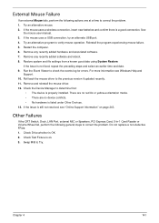
If the mouse uses a wireless connection, insert new batteries and confirm there is OK. 2. Reinstall the program experiencing mouse failure. 5. Restore system and file settings from a known good date using System Restore. For more ...
If the mouse uses a wireless connection, insert new batteries and confirm there is OK. 2. Reinstall the program experiencing mouse failure. 5. Restore system and file settings from a known good date using System Restore. For more ...


