Quick Start Guide
Page 5
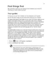
... the model you get started with setting up your notebook. In addition it : 1 Click on Start > All Programs > AcerSystem. 2 Click on AcerSystem User Guide. Follow the instructions on the screen to the AcerSystem User Guide. Please understand that due to its nature, the Generic User Guide as well as "only for your mobile computing needs. It covers basic topics such as system utilities, data recovery, expansion options and troubleshooting...
... the model you get started with setting up your notebook. In addition it : 1 Click on Start > All Programs > AcerSystem. 2 Click on AcerSystem User Guide. Follow the instructions on the screen to the AcerSystem User Guide. Please understand that due to its nature, the Generic User Guide as well as "only for your mobile computing needs. It covers basic topics such as system utilities, data recovery, expansion options and troubleshooting...
Quick Start Guide
Page 7
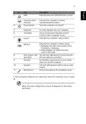
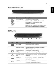
... functions like a computer mouse. 7 Power1 Indicates the computer's power status. English 5 # Icon 3 Item HDD Description Indicates when the hard disk drive is charging. 2. Charging: The light shows amber when the battery is active. Communication indicator Indicates the computer's wireless connectivity device status. 4 Power button Turns the computer on the model purchased. The front panel indicators are visible even when the computer cover is closed up. Note: The exact configuration of your PC depends on and off. 5 Keyboard For entering...
... functions like a computer mouse. 7 Power1 Indicates the computer's power status. English 5 # Icon 3 Item HDD Description Indicates when the hard disk drive is charging. 2. Charging: The light shows amber when the battery is active. Communication indicator Indicates the computer's wireless connectivity device status. 4 Power button Turns the computer on the model purchased. The front panel indicators are visible even when the computer cover is closed up. Note: The exact configuration of your PC depends on and off. 5 Keyboard For entering...
Quick Start Guide
Page 8
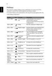
... sound volume. Stop Stop playing the selected media file. To activate hotkeys, press and hold the key before pressing the other key in Sleep mode. + + + + Display toggle Display off . Hotkey + + Icon Function Description Communication Enables/disables the computer's key communication devices. (Communication devices may vary by configuration). Turns the internal touchpad on and off to save power. Previous Return to return. Next Jump to access most of the computer's controls like screen brightness and volume output. Increases the sound volume...
... sound volume. Stop Stop playing the selected media file. To activate hotkeys, press and hold the key before pressing the other key in Sleep mode. + + + + Display toggle Display off . Hotkey + + Icon Function Description Communication Enables/disables the computer's key communication devices. (Communication devices may vary by configuration). Turns the internal touchpad on and off to save power. Previous Return to return. Next Jump to access most of the computer's controls like screen brightness and volume output. Increases the sound volume...
Quick Start Guide
Page 9
... 4 56 7 Item DC-in -1 card reader Description Accepts Secure Digital (SD), MultiMediaCard (MMC), Memory Stick (MS), Memory Stick PRO (MS PRO), xD-Picture Card (xD). HDMI port USB 2.0 port Supports high definition digital video connections. Ventilation slots External display (VGA) port Enable the computer to an AC adapter. Connects to USB 2.0 devices (e.g., USB mouse, USB camera). Connect to a display device (e.g., external monitor, LCD projector). Only one card can operate at any given time. Ethernet (RJ-45) Connects to remove/install the card. Note: Push to an Ethernet...
... 4 56 7 Item DC-in -1 card reader Description Accepts Secure Digital (SD), MultiMediaCard (MMC), Memory Stick (MS), Memory Stick PRO (MS PRO), xD-Picture Card (xD). HDMI port USB 2.0 port Supports high definition digital video connections. Ventilation slots External display (VGA) port Enable the computer to an AC adapter. Connects to USB 2.0 devices (e.g., USB mouse, USB camera). Connect to a display device (e.g., external monitor, LCD projector). Only one card can operate at any given time. Ethernet (RJ-45) Connects to remove/install the card. Note: Push to an Ethernet...
Service Guide
Page 7
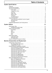
... Indicators 9 TouchPad Basics 10 Using the Keyboard 11 Lock Keys and embedded numeric keypad 11 Windows Keys 12 Hot Keys 13 Hardware Specifications and Configurations 14 System Utilities 21 BIOS Setup Utility 21 Navigating the BIOS Utility 21 Aspire 5741/5741G BIOS 22 Information 22 Main 23 Security 24 Boot 27 Exit 28 BIOS Flash Utilities 29 DOS Flash Utility 30 WinFlash Utility 32 Remove HDD/BIOS Password Utilities 33 Machine Disassembly and Replacement 39 Disassembly Requirements 39 Pre-disassembly Instructions 40 Disassembly Process 41 External Module Disassembly...
... Indicators 9 TouchPad Basics 10 Using the Keyboard 11 Lock Keys and embedded numeric keypad 11 Windows Keys 12 Hot Keys 13 Hardware Specifications and Configurations 14 System Utilities 21 BIOS Setup Utility 21 Navigating the BIOS Utility 21 Aspire 5741/5741G BIOS 22 Information 22 Main 23 Security 24 Boot 27 Exit 28 BIOS Flash Utilities 29 DOS Flash Utility 30 WinFlash Utility 32 Remove HDD/BIOS Password Utilities 33 Machine Disassembly and Replacement 39 Disassembly Requirements 39 Pre-disassembly Instructions 40 Disassembly Process 41 External Module Disassembly...
Service Guide
Page 8
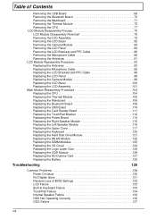
... Keyboard 120 Replacing the Hard Disk Drive Module 121 Replacing the WLAN Module 122 Replacing the DIMM Modules 123 Replacing the 3G Cover 124 Replacing the Logic Lower Door 125 Replacing the ODD Module 126 Replacing the SD Dummy Card 127 Replacing the Battery 128 Troubleshooting 129 Common Problems 129 Power On Issue 130 No Display Issue 131 Random Loss of BIOS Settings 132 LCD Failure 133 Built-In Keyboard Failure 133 TouchPad Failure 134 Internal Speaker Failure 134 HDD...
... Keyboard 120 Replacing the Hard Disk Drive Module 121 Replacing the WLAN Module 122 Replacing the DIMM Modules 123 Replacing the 3G Cover 124 Replacing the Logic Lower Door 125 Replacing the ODD Module 126 Replacing the SD Dummy Card 127 Replacing the Battery 128 Troubleshooting 129 Common Problems 129 Power On Issue 130 No Display Issue 131 Random Loss of BIOS Settings 132 LCD Failure 133 Built-In Keyboard Failure 133 TouchPad Failure 134 Internal Speaker Failure 134 HDD...
Service Guide
Page 13
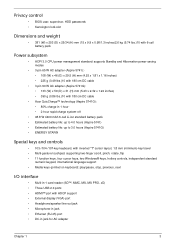
...-gesture touchpad, supporting two-finger scroll, pinch, rotate, flip • 11 function keys, four cursor keys, two Windows® keys, hotkey controls, independent standard numeric keypad, international language support • Media keys (printed on keyboard): play/pause, stop, previous, next I/O interface • Multi-in-1 card reader (SD™, MMC, MS, MS PRO, xD) • Three USB 2.0 ports • HDMI™ port with HDCP support • External display (VGA) port • Headphone/speaker/line-out jack • Microphone-in jack...
...-gesture touchpad, supporting two-finger scroll, pinch, rotate, flip • 11 function keys, four cursor keys, two Windows® keys, hotkey controls, independent standard numeric keypad, international language support • Media keys (printed on keyboard): play/pause, stop, previous, next I/O interface • Multi-in-1 card reader (SD™, MMC, MS, MS PRO, xD) • Three USB 2.0 ports • HDMI™ port with HDCP support • External display (VGA) port • Headphone/speaker/line-out jack • Microphone-in jack...
Service Guide
Page 17
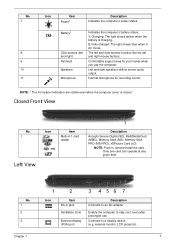
... computer cover is charging. 2. Connects to remove/install the card. Fully charged: The light shows blue when in jack Ventilation slots External display (VGA) port Description Connects to an AC adapter Enable the computer to stay cool, even after prolonged use the computer. Only one card can operate at any given time. NOTE: Push to a display device (e.g. external monitor, LCD projector). Battery1 Click buttons (left and right mouse buttons. Chapter 1 7 No. 1 2 3 1 2 3 4 56 7 Icon Item DC-in AC mode. Internal microphone...
... computer cover is charging. 2. Connects to remove/install the card. Fully charged: The light shows blue when in jack Ventilation slots External display (VGA) port Description Connects to an AC adapter Enable the computer to stay cool, even after prolonged use the computer. Only one card can operate at any given time. NOTE: Push to a display device (e.g. external monitor, LCD projector). Battery1 Click buttons (left and right mouse buttons. Chapter 1 7 No. 1 2 3 1 2 3 4 56 7 Icon Item DC-in AC mode. Internal microphone...
Service Guide
Page 32
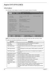
... number of the system. InsydeH20 Setup Utility Information Main Security Boot Exit Rev. 3.5 CPU Type CPU Speed HDD Model Name: HDD Serial Number: ATAPI Model Name: System BIOS Version: KBC BIOS Version: VGA BIOS Version: Serial Number: Asset Tag Number: Product Name: Manufacturer Name: UUID: Intel(R) Core(TM) i3 CPU 2.13GHz M 330 @ 2.13GHz WDC WD3200BEVT-22A23T0 WD-WXB0AA9N9724 HL-DT-STDVDRAM GT30N V0.11 V0.11 Intel V1946 NEW7021011001268A81601 Aspire 5741/5741G Acer...
... number of the system. InsydeH20 Setup Utility Information Main Security Boot Exit Rev. 3.5 CPU Type CPU Speed HDD Model Name: HDD Serial Number: ATAPI Model Name: System BIOS Version: KBC BIOS Version: VGA BIOS Version: Serial Number: Asset Tag Number: Product Name: Manufacturer Name: UUID: Intel(R) Core(TM) i3 CPU 2.13GHz M 330 @ 2.13GHz WDC WD3200BEVT-22A23T0 WD-WXB0AA9N9724 HL-DT-STDVDRAM GT30N V0.11 V0.11 Intel V1946 NEW7021011001268A81601 Aspire 5741/5741G Acer...
Service Guide
Page 33
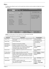
... pleasing and comfortable display (OEM Logo screen). Displays the available memory for the hour field. Enables, disables Boot Menu during POST with 24hour format. The function allows the user to create a hidden partition on hard disc drive to store operation system and restore the system to factory defaults. Format/Option Format: HH:MM:SS (hour:minute:second) Format MM/DD/YYYY (month/day/year) N/A N/A Option: Enabled or Disabled Option: Enabled or Disabled Option: Enabled or Enabled Option: Enabled or Disabled Option: AHCI Mode or IDE Mode Options: Integrated Graphics, Discrete...
... pleasing and comfortable display (OEM Logo screen). Displays the available memory for the hour field. Enables, disables Boot Menu during POST with 24hour format. The function allows the user to create a hidden partition on hard disc drive to store operation system and restore the system to factory defaults. Format/Option Format: HH:MM:SS (hour:minute:second) Format MM/DD/YYYY (month/day/year) N/A N/A Option: Enabled or Disabled Option: Enabled or Disabled Option: Enabled or Enabled Option: Enabled or Disabled Option: AHCI Mode or IDE Mode Options: Integrated Graphics, Discrete...
Service Guide
Page 35
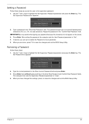
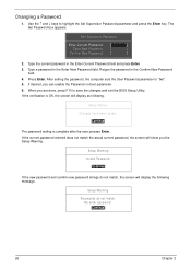
... the BIOS Setup Utility. IMPORTANT:Be very careful when typing your password because the characters do not appear on boot parameter. 5. Chapter 2 25 If desired, you have changed the settings, press u to enable the Password on the screen. 3. The Set Password box appears: Set Supervisor Password Enter Current Password [ ] Enter New Password [ ] Confirm New Password [ ] 2. Use the ↑ and ↓ keys to highlight the Set Supervisor Password parameter and press the Enter key. Type the current password in the "Enter New Password" field. Type a password...
... the BIOS Setup Utility. IMPORTANT:Be very careful when typing your password because the characters do not appear on boot parameter. 5. Chapter 2 25 If desired, you have changed the settings, press u to enable the Password on the screen. 3. The Set Password box appears: Set Supervisor Password Enter Current Password [ ] Enter New Password [ ] Confirm New Password [ ] 2. Use the ↑ and ↓ keys to highlight the Set Supervisor Password parameter and press the Enter key. Type the current password in the "Enter New Password" field. Type a password...
Service Guide
Page 36
... screen will display as following message. Type a password in the Enter New Password field. After setting the password, the computer sets the User Password parameter to highlight the Set Supervisor Password parameter and press the Enter key. When you are done, press F10 to save the changes and exit the BIOS Setup Utility. The Set Password box appears. Press Enter. If the verification is complete after the user presses Enter. Setup Warning Invalid Password. [Continue] If the new password...
... screen will display as following message. Type a password in the Enter New Password field. After setting the password, the computer sets the User Password parameter to highlight the Set Supervisor Password parameter and press the Enter key. When you are done, press F10 to save the changes and exit the BIOS Setup Utility. The Set Password box appears. Press Enter. If the verification is complete after the user presses Enter. Setup Warning Invalid Password. [Continue] If the new password...
Service Guide
Page 64
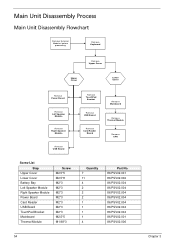
Main Unit Disassembly Process Main Unit Disassembly Flowchart Remove External Modules before proceeding Remove Keyboard Remove Upper Cover Upper Cover Lower Cover Remove Power Board Remove Left Speaker Module Remove Right Speaker Module Remove USB Board Remove TouchPad Bracket Remove USB Board Remove Card Reader Board Remove Mainboard Remove Thermal Module Remove CPU Screw List Step Upper Cover Lower Cover Battery Bay Left Speaker Module Right Speaker Module Power Board Card Reader USB Board TouchPad Bracket Mainboard Thermal Module Screw M2.5*5 M2.5*8 M2*3 M2*3 M2*3 M2*3 M2*3 M2*3 ...
Main Unit Disassembly Process Main Unit Disassembly Flowchart Remove External Modules before proceeding Remove Keyboard Remove Upper Cover Upper Cover Lower Cover Remove Power Board Remove Left Speaker Module Remove Right Speaker Module Remove USB Board Remove TouchPad Bracket Remove USB Board Remove Card Reader Board Remove Mainboard Remove Thermal Module Remove CPU Screw List Step Upper Cover Lower Cover Battery Bay Left Speaker Module Right Speaker Module Power Board Card Reader USB Board TouchPad Bracket Mainboard Thermal Module Screw M2.5*5 M2.5*8 M2*3 M2*3 M2*3 M2*3 M2*3 M2*3 ...
Service Guide
Page 139
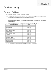
... the same operation. 3. Use the following procedure as possible. 2. Obtain the failing symptoms in as much detail as a guide for computer problems. NOTE: The diagnostic tests are intended to test only Acer products. Chapter 4 129 Symptoms (Verified) Go To Power On Issue Page 130 No Display Issue Page 131 LCD Failure Page 133 Internal Keyboard Failure Page 133 TouchPad Failure Page...
... the same operation. 3. Use the following procedure as possible. 2. Obtain the failing symptoms in as much detail as a guide for computer problems. NOTE: The diagnostic tests are intended to test only Acer products. Chapter 4 129 Symptoms (Verified) Go To Power On Issue Page 130 No Display Issue Page 131 LCD Failure Page 133 Internal Keyboard Failure Page 133 TouchPad Failure Page...
Service Guide
Page 141
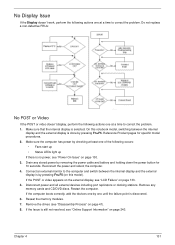
... one of the following occurs: • Fans start up • Status LEDs light up If there is done by removing the power cable and battery and holding down the power button for specific model procedures. 2. Drain any memory cards and CD/DVD discs. Disconnect power and all external devices including port replicators or docking stations. Reseat the memory modules. 7. On this notebook model, switching between the internal display and the external display is by one until the failure point...
... one of the following occurs: • Fans start up • Status LEDs light up If there is done by removing the power cable and battery and holding down the power button for specific model procedures. 2. Drain any memory cards and CD/DVD discs. Disconnect power and all external devices including port replicators or docking stations. Reseat the memory modules. 7. On this notebook model, switching between the internal display and the external display is by one until the failure point...
Service Guide
Page 142
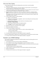
... User Manual for instructions on page 41. 3. c. Readjust if necessary. 6. Remove and reinstall the video driver. 8. Run the Windows Memory Diagnostic from the BIOS, the drive may reduce display brightness. Run a complete virus scan using up-to-date software to the previous version if updated. 7. If the BIOS settings are no device conflicts. • No hardware is listed under Other Devices. 9. Reboot the computer. 2. See "Disassembly Process" on adjusting settings. Check the display resolution is experiencing HDD...
... User Manual for instructions on page 41. 3. c. Readjust if necessary. 6. Remove and reinstall the video driver. 8. Run the Windows Memory Diagnostic from the BIOS, the drive may reduce display brightness. Run a complete virus scan using up-to-date software to the previous version if updated. 7. If the BIOS settings are no device conflicts. • No hardware is listed under Other Devices. 9. Reboot the computer. 2. See "Disassembly Process" on adjusting settings. Check the display resolution is experiencing HDD...
Service Guide
Page 146
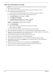
... a time to locate and resolve issues with the computer. Run the Windows Vista Startup Repair Utility: a. c. The System Recovery Options screen displays. Select the appropriate operating system, and click Next. Run Windows Check Disk by entering chkdsk /r from a known good date using up-to-date software to the operating system DVD. Run a complete virus scan using System Restore. insert the Windows Vista Operating System DVD in the ODD and restart the computer. The Install Windows screen displays. e. When...
... a time to locate and resolve issues with the computer. Run the Windows Vista Startup Repair Utility: a. c. The System Recovery Options screen displays. Select the appropriate operating system, and click Next. Run Windows Check Disk by entering chkdsk /r from a known good date using up-to-date software to the operating system DVD. Run a complete virus scan using System Restore. insert the Windows Vista Operating System DVD in the ODD and restart the computer. The Install Windows screen displays. e. When...
Service Guide
Page 149
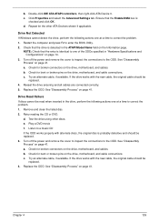
... Model Name field on the drive, motherboard, and cables. Chapter 4 139 b. Check that the Enable DMA box is detected in "Hardware Specifications and Configurations" on the drive, motherboard, and cable connections. c. If the drive works with the new cable, the original cable should be replaced. 3. Reseat the drive ensuring and all cables are connected correctly. 5. Test the drive using other ATA Devices shown if applicable. Turn off the power and remove the cover to inspect the connections to enter the BIOS Utility...
... Model Name field on the drive, motherboard, and cables. Chapter 4 139 b. Check that the Enable DMA box is detected in "Hardware Specifications and Configurations" on the drive, motherboard, and cable connections. c. If the drive works with the new cable, the original cable should be replaced. 3. Reseat the drive ensuring and all cables are connected correctly. 5. Test the drive using other ATA Devices shown if applicable. Turn off the power and remove the cover to inspect the connections to enter the BIOS Utility...
Service Guide
Page 151
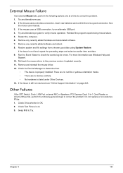
... an external Mouse fails, perform the following general steps to correct the problem. If the mouse uses a USB connection, try an alternate USB port. 4. Run the Event Viewer to verify mouse operation. Remove and reinstall the mouse driver. 12. Restore system and file settings from a known good date using System Restore. Check the Device Manager to the previous version if updated recently. 11. If the mouse uses a wireless connection, insert new batteries and confirm there is not fixed...
... an external Mouse fails, perform the following general steps to correct the problem. If the mouse uses a USB connection, try an alternate USB port. 4. Run the Event Viewer to verify mouse operation. Remove and reinstall the mouse driver. 12. Restore system and file settings from a known good date using System Restore. Check the Device Manager to the previous version if updated recently. 11. If the mouse uses a wireless connection, insert new batteries and confirm there is not fixed...
Service Guide
Page 255
... Device Configuration 25 Power 27 Save and Exit 28 Security 24 System Security 28 Board Layout Top View 149 brightness hotkeys 13 C Camera Module Removing 83 Replacing 96, 98, 99, 101 Common Problems 130 computer on indicator 9 CPU Removing 77 Replacing 104 D DIMM Modules Replacing 123 Display 5 Index display hotkeys 13 E EasyTouch Failure 140 External Module Disassembly Flowchart 42 F Features 1 Flash Utility 29 FPC Cable Removing 86 FRU (Field Replaceable Unit) List 155 H Hard Disk Drive Removing 52 Replacing 121 HDTV Switch Failure 141 Hibernation mode hotkey...
... Device Configuration 25 Power 27 Save and Exit 28 Security 24 System Security 28 Board Layout Top View 149 brightness hotkeys 13 C Camera Module Removing 83 Replacing 96, 98, 99, 101 Common Problems 130 computer on indicator 9 CPU Removing 77 Replacing 104 D DIMM Modules Replacing 123 Display 5 Index display hotkeys 13 E EasyTouch Failure 140 External Module Disassembly Flowchart 42 F Features 1 Flash Utility 29 FPC Cable Removing 86 FRU (Field Replaceable Unit) List 155 H Hard Disk Drive Removing 52 Replacing 121 HDTV Switch Failure 141 Hibernation mode hotkey...


