
Aspire 5515 Quick Guide - EN
Page 10
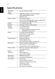
... keys • and controls • I/O interface • • • • • • Genuine Windows Vista® AMD Athlon 2650e* processor or higher AMD RS690MC/SB600 Chipset IEEE 802.11b/g Dual-channel support Up to 2 GB of DDR2 667 MHz memory, upgradeable to 4 GB using two soDIMM modules 15.4" WXGA 1280 x 800...
... keys • and controls • I/O interface • • • • • • Genuine Windows Vista® AMD Athlon 2650e* processor or higher AMD RS690MC/SB600 Chipset IEEE 802.11b/g Dual-channel support Up to 2 GB of DDR2 667 MHz memory, upgradeable to 4 GB using two soDIMM modules 15.4" WXGA 1280 x 800...
Acer Aspire 5515 Notebook Service Guide
Page 9
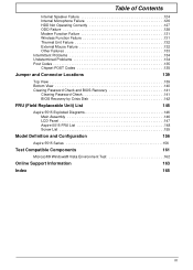
...Chipset POST Codes 135 Jumper and Connector Locations 139 Top View 139 Bottom View 140 Clearing Password Check and BIOS Recovery 141 Clearing Password Check 141 BIOS Recovery by Crisis Disk 142 FRU (Field Replaceable Unit) List 145 Aspire 5515 Exploded Diagrams 146 Main Assembly 146 LCD Panel 147 Aspire 5515... FRU List 148 Screw List 155 Model Definition and Configuration 156 Aspire 5515 Series 156 Test Compatible Components 161 Microsoft®...
...Chipset POST Codes 135 Jumper and Connector Locations 139 Top View 139 Bottom View 140 Clearing Password Check and BIOS Recovery 141 Clearing Password Check 141 BIOS Recovery by Crisis Disk 142 FRU (Field Replaceable Unit) List 145 Aspire 5515 Exploded Diagrams 146 Main Assembly 146 LCD Panel 147 Aspire 5515... FRU List 148 Screw List 155 Model Definition and Configuration 156 Aspire 5515 Series 156 Test Compatible Components 161 Microsoft®...

Acer Aspire 5515 Notebook Service Guide
Page 27
... RTL8102EL for 10/100 LAN Supports LAN protocol LAN connector type RJ-45 LAN connector location Left side Features Wireless Module 802.11b/g Item Specification Chipset Data throughput Protocol Chapter 1 17 On above table, the configuration of slot 1 and slot 2 could be reversed. You may combine DIMMs with various capacities to...
... RTL8102EL for 10/100 LAN Supports LAN protocol LAN connector type RJ-45 LAN connector location Left side Features Wireless Module 802.11b/g Item Specification Chipset Data throughput Protocol Chapter 1 17 On above table, the configuration of slot 1 and slot 2 could be reversed. You may combine DIMMs with various capacities to...
Acer Aspire 5515 Notebook Service Guide
Page 35
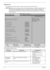
... system from booting, open BIOS and choose Load Optimal Defaults in the Exit menu to boot up normally. Enter the Advanced Chipset Control menu. Unless you have experience adjusting these items, we recommend that you leave these pages may cause the system to... in boldface are the default and suggested parameter settings. PhoenixBIOS Setup Utility Information Main Advanced Security Power Boot XPnP Configuration XVideo Display Configuration XAdvanced Chipset Control PS/2 Mouse IDE Controller: On chip SATA SATA Mode: SATA Smbus Interface [Enabled] [Disabled] [Enabled] [IDE AHCI] [Enabled...
... system from booting, open BIOS and choose Load Optimal Defaults in the Exit menu to boot up normally. Enter the Advanced Chipset Control menu. Unless you have experience adjusting these items, we recommend that you leave these pages may cause the system to... in boldface are the default and suggested parameter settings. PhoenixBIOS Setup Utility Information Main Advanced Security Power Boot XPnP Configuration XVideo Display Configuration XAdvanced Chipset Control PS/2 Mouse IDE Controller: On chip SATA SATA Mode: SATA Smbus Interface [Enabled] [Disabled] [Enabled] [IDE AHCI] [Enabled...
Acer Aspire 5515 Notebook Service Guide
Page 146
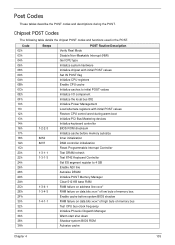
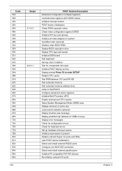
... 1-2-2-3 8254 8237 1-3-1-1 1-3-1-3 1-3-4-1 1-3-4-3 1-4-1-1 POST Routine Description Verify Real Mode Disable Non-Maskable Interrupt (NMI) Get CPU type Initialize system hardware Initialize chipset with initial POST values Set IN POST flag Initialize CPU registers Enable CPU cache Initialize caches to 4 GB Enable A20 line Autosize DRAM Initialize POST... the local bus IDE Initialize Power Management Load alternate registers with initial POST values Restore CPU control word during the POST. Chipset POST Codes The following table details the chipset POST codes and functions used in the POST.
... 1-2-2-3 8254 8237 1-3-1-1 1-3-1-3 1-3-4-1 1-3-4-3 1-4-1-1 POST Routine Description Verify Real Mode Disable Non-Maskable Interrupt (NMI) Get CPU type Initialize system hardware Initialize chipset with initial POST values Set IN POST flag Initialize CPU registers Enable CPU cache Initialize caches to 4 GB Enable A20 line Autosize DRAM Initialize POST... the local bus IDE Initialize Power Management Load alternate registers with initial POST values Restore CPU control word during the POST. Chipset POST Codes The following table details the chipset POST codes and functions used in the POST.
Acer Aspire 5515 Notebook Service Guide
Page 147
... 69h 6Ah 6Bh 6Ch 6Eh 70h 72h 76h 7Ch 7Eh 80h 81h 82h 83h 84h 85h 86h 136 Beeps 2-1-2-3 2-2-3-1 POST Routine Description Advanced configuration of chipset registers Load alternate registers with CMOS values Initialize interrupt vectors POST device initialization Check ROM copyright notice Check video configuration against CMOS Initialize PCI bus...
... 69h 6Ah 6Bh 6Ch 6Eh 70h 72h 76h 7Ch 7Eh 80h 81h 82h 83h 84h 85h 86h 136 Beeps 2-1-2-3 2-2-3-1 POST Routine Description Advanced configuration of chipset registers Load alternate registers with CMOS values Initialize interrupt vectors POST device initialization Check ROM copyright notice Check video configuration against CMOS Initialize PCI bus...
Acer Aspire 5515 Notebook Service Guide
Page 149
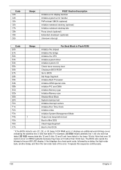
...-bitmap (xxxx) indicating the address line or bits that error 30 cannot occur on 386SX systems because they have failed in Flash ROM Initialize the chipset Initialize the bridge Initialize the CPU Initialize system timer Initialize system I/O Check force recovery boot Checksum BIOS ROM Go to the port-80 LED display...
...-bitmap (xxxx) indicating the address line or bits that error 30 cannot occur on 386SX systems because they have failed in Flash ROM Initialize the chipset Initialize the bridge Initialize the CPU Initialize system timer Initialize system I/O Check force recovery boot Checksum BIOS ROM Go to the port-80 LED display...


