
AL1912 Service Guide
Page 6
... to the nature of the fluorescent light, the screen may find slightly uneven brightness in the screen depending on again to the nature of the LCD screen, an afterimage of the previous screen may include blemishes of 0.01% or less such as a missing pixel or a pixel lit all of 99.99... and then turn it on the desktop pattern you use . Due to make sure the flicker disappears. Turn off the Power Switch for hours. The LCD screen has effective pixels of the time. SPECIAL NOTES ON...
... to the nature of the fluorescent light, the screen may find slightly uneven brightness in the screen depending on again to the nature of the LCD screen, an afterimage of the previous screen may include blemishes of 0.01% or less such as a missing pixel or a pixel lit all of 99.99... and then turn it on the desktop pattern you use . Due to make sure the flicker disappears. Turn off the Power Switch for hours. The LCD screen has effective pixels of the time. SPECIAL NOTES ON...
AL1912 Service Guide
Page 8
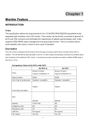
...sub VGA connector and eliminates the requirement of AL1912 m/AL1912 AL1912 m Panel Normal 19" panel Fujitsu FLC48SXC8V-10 Signal Interface Sync Type for the 19" MICRO-PROCESSOR based Multi-mode supported high resolution color LCD monitor. Comparison Chart of optional special display ...card. Monitor Feature INTRODUCTION Chapter 1 Scope This specification defines the requirements for analog input DSUB Separate / compatible / AL1912 Normal 19" panel Fujitsu FLC48SXC8V-10 DSUB...
...sub VGA connector and eliminates the requirement of AL1912 m/AL1912 AL1912 m Panel Normal 19" panel Fujitsu FLC48SXC8V-10 Signal Interface Sync Type for the 19" MICRO-PROCESSOR based Multi-mode supported high resolution color LCD monitor. Comparison Chart of optional special display ...card. Monitor Feature INTRODUCTION Chapter 1 Scope This specification defines the requirements for analog input DSUB Separate / compatible / AL1912 Normal 19" panel Fujitsu FLC48SXC8V-10 DSUB...
AL1912 Service Guide
Page 9
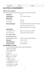
... Hz MEASUREMENT SYSTEMS The units of measure stated in this document are listed below: 1 gamma = 1 nano tesla 1 tesla = 10,000 gauss cm = in front of LCD panel Warrn up time All specifications : 30 minutes Fully functional : 5 seconds Measuring Equipment : Chroma 2250 signal generator or equivalent, directly Connected to the monitor under...
... Hz MEASUREMENT SYSTEMS The units of measure stated in this document are listed below: 1 gamma = 1 nano tesla 1 tesla = 10,000 gauss cm = in front of LCD panel Warrn up time All specifications : 30 minutes Fully functional : 5 seconds Measuring Equipment : Chroma 2250 signal generator or equivalent, directly Connected to the monitor under...
AL1912 Service Guide
Page 10
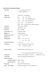
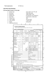
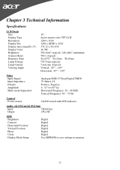
... specification Panel Type: 19 " active matrix color TFT LCD 1). Fujitsu FLC48SXC8V-10 Display size: Display mode: Pixel pitch: Display Dot: Pixel Clock: Contrast ratio: θ = 0˚ Brightness: Response time (Tr/Tf): ... positive or negative Signal connector: 15 pin Mini D type, (standard VGA video) 3.5 mm stereo audio jack (Audio) (For AL1912 m only) Audio power: 0.5Wrms + 0.5Wrms (300Hz - 10kHz (S.P.L. - 10 dB))(AL1912 m only) Front control: power on/off with LED select adjustment (+,-) Interface frequency Horizontal Frequency 24KHz --80KHz Vertical Frequency 49Hz ------75Hz...
... specification Panel Type: 19 " active matrix color TFT LCD 1). Fujitsu FLC48SXC8V-10 Display size: Display mode: Pixel pitch: Display Dot: Pixel Clock: Contrast ratio: θ = 0˚ Brightness: Response time (Tr/Tf): ... positive or negative Signal connector: 15 pin Mini D type, (standard VGA video) 3.5 mm stereo audio jack (Audio) (For AL1912 m only) Audio power: 0.5Wrms + 0.5Wrms (300Hz - 10kHz (S.P.L. - 10 dB))(AL1912 m only) Front control: power on/off with LED select adjustment (+,-) Interface frequency Horizontal Frequency 24KHz --80KHz Vertical Frequency 49Hz ------75Hz...
AL1912 Service Guide
Page 11
LCD Panel Specification LCD Panel Model (Hydis LT17E12-200) • Display Type • Resolution • Display Dot • Display Area • Pixel Pitch • Display Color • Lamp Voltage • Lamp Current • Weight • Optical Specifications active matrix color TFT LCD 1280x1024 pixels 1280x (RGB) x 1024 376.32mm(H) x 301.056mm(V) 0.294mm(H) x 0.294mm(V) 16M 750 Vrms (typ) 7 mArms (typ) 2500g (Max) - 11 - Total output power: 60 Watt max.
LCD Panel Specification LCD Panel Model (Hydis LT17E12-200) • Display Type • Resolution • Display Dot • Display Area • Pixel Pitch • Display Color • Lamp Voltage • Lamp Current • Weight • Optical Specifications active matrix color TFT LCD 1280x1024 pixels 1280x (RGB) x 1024 376.32mm(H) x 301.056mm(V) 0.294mm(H) x 0.294mm(V) 16M 750 Vrms (typ) 7 mArms (typ) 2500g (Max) - 11 - Total output power: 60 Watt max.
AL1912 Service Guide
Page 12
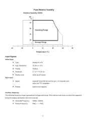
...; Type • Input Impedance • Polarity • Amplitude • Display Color Sync input • Signal • Polarity Analog R, G, B. 75 ohm +/- 2% Positive 0 - 0.7 +/- 0.05 Vp same as LCD panel separate horizontal and vertical sync, or composite sync which are TTL compatible positive and negative. If the entered mode does not match the supported...
...; Type • Input Impedance • Polarity • Amplitude • Display Color Sync input • Signal • Polarity Analog R, G, B. 75 ohm +/- 2% Positive 0 - 0.7 +/- 0.05 Vp same as LCD panel separate horizontal and vertical sync, or composite sync which are TTL compatible positive and negative. If the entered mode does not match the supported...
AL1912 Service Guide
Page 15
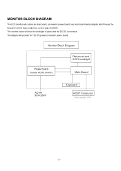
The Adapter will drive the backlight of panel and the DC-DC conversion. The inverter board will provide thr 12V DC-power to inverter/ power board. Power board (include: AC/DC,inverter) - 15 - MONITOR BLOCK DIAGRAM The LCD monitor will contain an main board, an inverter/ power board, key board and internal adapter which house the flat panel control logic, brightness control logic and DDC.
The Adapter will drive the backlight of panel and the DC-DC conversion. The inverter board will provide thr 12V DC-power to inverter/ power board. Power board (include: AC/DC,inverter) - 15 - MONITOR BLOCK DIAGRAM The LCD monitor will contain an main board, an inverter/ power board, key board and internal adapter which house the flat panel control logic, brightness control logic and DDC.
AL1912 Service Guide
Page 20
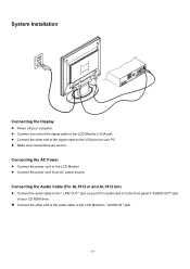
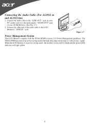
Connect one end of the audio cable to the LCD Monitor's " AUDIO IN " jack. - 20 - Connecting the Audio Cable (For AL1912 m and AL1912 bm) Connect the audio cable to the " LINE OUT " jack on your PC. Connect the power cord to the LCD Monitor. System Installation Connecting the Display Power off your CD ROM drive... signal cable to the VGA port on your PC's audio card or to the front panel's "AUDIO OUT" jack of the signal cable to the LCD Monitor's VGA port.
Connect one end of the audio cable to the LCD Monitor's " AUDIO IN " jack. - 20 - Connecting the Audio Cable (For AL1912 m and AL1912 bm) Connect the audio cable to the " LINE OUT " jack on your PC. Connect the power cord to the LCD Monitor. System Installation Connecting the Display Power off your CD ROM drive... signal cable to the VGA port on your PC's audio card or to the front panel's "AUDIO OUT" jack of the signal cable to the LCD Monitor's VGA port.
AL1912 Service Guide
Page 23
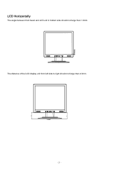
LCD Horizontally The angle between front bezel and LCD unit in bottom side should not large than 1.0mm. The distance of the LCD display unit from left side to right should not large than 4.0mm. - 23 -
LCD Horizontally The angle between front bezel and LCD unit in bottom side should not large than 1.0mm. The distance of the LCD display unit from left side to right should not large than 4.0mm. - 23 -
AL1912 User's Guide
Page 1
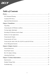
... ...2 Canadian DOC Notice ...2 Important Safety Instructions...3 Chapter 1 Installation ...4 Unpacking...4 Connecting the LCD Monitor and Base 4 Viewing Angle Adjustment ...4 Detaching LCD Monitor from Its Stand 5 Interface for Arm Applications ...5 Connecting the Display...5 Connecting the AC Power ...5 Connecting the Audio Cable (For AL1912 m and AL1912 bm 6 Power Management System...6 Chapter 2 Display Controls 7 General Instructions...7 Front Panel...
... ...2 Canadian DOC Notice ...2 Important Safety Instructions...3 Chapter 1 Installation ...4 Unpacking...4 Connecting the LCD Monitor and Base 4 Viewing Angle Adjustment ...4 Detaching LCD Monitor from Its Stand 5 Interface for Arm Applications ...5 Connecting the Display...5 Connecting the AC Power ...5 Connecting the Audio Cable (For AL1912 m and AL1912 bm 6 Power Management System...6 Chapter 2 Display Controls 7 General Instructions...7 Front Panel...

AL1912 User's Guide
Page 2
... by any mechanical, electronic or other means, in any form, without notice. You are cautioned that to assist users in setting up and using the LCD Monitor. Preface This manual is designed to which can radiate radio frequency energy, and if not installed and used in accordance with the limits for...
... by any mechanical, electronic or other means, in any form, without notice. You are cautioned that to assist users in setting up and using the LCD Monitor. Preface This manual is designed to which can radiate radio frequency energy, and if not installed and used in accordance with the limits for...
AL1912 User's Guide
Page 3
... monitor and call an authorized technician. * Monitor to PC signal cable is frayed or damaged. * Liquid spilled into LCD Monitor or the monitor has been exposed to rain. * LCD Monitor or the case is damaged. 7. Exposing the monitor to the display. 4. Do not remove the cover or...this range could result in a room with dampened rag. 2. Only use . 1. Do not place the LCD Monitor near a window. Store LCD Monitor in permanent damage. 6. To clean LCD Monitor screen; -- Power off LCD Monitor and unplug the AC Cord. -- Gently clean the screen with a room temperature of the following ...
... monitor and call an authorized technician. * Monitor to PC signal cable is frayed or damaged. * Liquid spilled into LCD Monitor or the monitor has been exposed to rain. * LCD Monitor or the case is damaged. 7. Exposing the monitor to the display. 4. Do not remove the cover or...this range could result in a room with dampened rag. 2. Only use . 1. Do not place the LCD Monitor near a window. Store LCD Monitor in permanent damage. 6. To clean LCD Monitor screen; -- Power off LCD Monitor and unplug the AC Cord. -- Gently clean the screen with a room temperature of the following ...
AL1912 User's Guide
Page 4
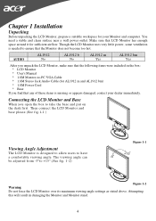
...take the base and put on the desk first. Attempting this will result in the box: * LCD Monitor * User's Manual * 1.8M Monitor-to-PC VGA Cable * 1.8M Stereo Jack Audio Cable (for AL1912 m and AL1912 bm) * 1.8M Power Cord * Base If you open the box to ensure that the ...following items were included in damaging the Monitor and Monitor stand. 4 AUDIO AL1912 No AL1912 b No AL1912 m Yes AL1912 bm Yes After you unpack the LCD Monitor, make sure that the Monitor does not become too hot. Though the LCD Monitor uses very little power, some ventilation is designed to allow users to ...
...take the base and put on the desk first. Attempting this will result in the box: * LCD Monitor * User's Manual * 1.8M Monitor-to-PC VGA Cable * 1.8M Stereo Jack Audio Cable (for AL1912 m and AL1912 bm) * 1.8M Power Cord * Base If you open the box to ensure that the ...following items were included in damaging the Monitor and Monitor stand. 4 AUDIO AL1912 No AL1912 b No AL1912 m Yes AL1912 bm Yes After you unpack the LCD Monitor, make sure that the Monitor does not become too hot. Though the LCD Monitor uses very little power, some ventilation is designed to allow users to ...
AL1912 User's Guide
Page 5
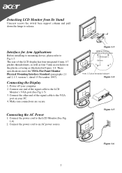
... meet the VESA Flat Panel Monitor Physical Mounting Interface Standard (paragraphs 2.1 and 2.1.3, version 1, dated 13 November 1997). Connect one end of this LCD display has four integrated 4 mm, 0.7 pitches threaded nuts, as well as four 5 mm access holes in the plastic covering as illustrated in Figure...your computer. 2. Make sure connections are secure. Interface for Arm Applications Before installing to mounting device, please refer to the LCD Monitor.(See Fig. 1-6) 2. Power off your PC. 4. Connecting the AC Power 1. Connect the other end of the signal cable to the...
... meet the VESA Flat Panel Monitor Physical Mounting Interface Standard (paragraphs 2.1 and 2.1.3, version 1, dated 13 November 1997). Connect one end of this LCD display has four integrated 4 mm, 0.7 pitches threaded nuts, as well as four 5 mm access holes in the plastic covering as illustrated in Figure...your computer. 2. Make sure connections are secure. Interface for Arm Applications Before installing to mounting device, please refer to the LCD Monitor.(See Fig. 1-6) 2. Power off your PC. 4. Connecting the AC Power 1. Connect the other end of the signal cable to the...
AL1912 User's Guide
Page 6
...LINE IN " jack. signal. The VESA DPMS provides four power saving modes through detecting a horizontal or vertical sync. Figure 1-7 Power Management System This LCD Monitor complies with the VESA DPMS (version 1.0) Power Management guidelines. Connect the other end of the audio cable to the front panel's "AUDIO OUT"... jack of your CD ROM drive. (See Fig. 1-7) 2. When the LCD Monitor is in power saving mode, the monitor screen will be blank and the power LED indicator will light yellow. 6 Connecting the Audio Cable (For...
...LINE IN " jack. signal. The VESA DPMS provides four power saving modes through detecting a horizontal or vertical sync. Figure 1-7 Power Management System This LCD Monitor complies with the VESA DPMS (version 1.0) Power Management guidelines. Connect the other end of the audio cable to the front panel's "AUDIO OUT"... jack of your CD ROM drive. (See Fig. 1-7) 2. When the LCD Monitor is in power saving mode, the monitor screen will be blank and the power LED indicator will light yellow. 6 Connecting the Audio Cable (For...
AL1912 User's Guide
Page 11
... Display Dot Display Area (mm)(H x V) Display Color Brightness Contrast Ratio Response Time Lamp Voltage Lamp Current Viewing Angle 19" Active matrix color TFT LCD 1280 x 1024 1280 x (RGB) x 1024 376.32 x 301.056 16.7M 300 cd/m2 (typical), 240 cd/m2 (minimum) 700... 0.05 Vp Horizontal Frequency: 24 ~ 80 KHz Vertical Frequency: 49 ~ 75 Hz Control Power switch On/Off switch with LED indicator Audio (AL1912 m/AL1912 bm) Input 500mVrms Output 1W+1W OSD Brightness Contrast Horizontal Position Vertical Position Phase Clock Display Mode Setup Digital Digital Digital Digital Digital Digital Use...
... Display Dot Display Area (mm)(H x V) Display Color Brightness Contrast Ratio Response Time Lamp Voltage Lamp Current Viewing Angle 19" Active matrix color TFT LCD 1280 x 1024 1280 x (RGB) x 1024 376.32 x 301.056 16.7M 300 cd/m2 (typical), 240 cd/m2 (minimum) 700... 0.05 Vp Horizontal Frequency: 24 ~ 80 KHz Vertical Frequency: 49 ~ 75 Hz Control Power switch On/Off switch with LED indicator Audio (AL1912 m/AL1912 bm) Input 500mVrms Output 1W+1W OSD Brightness Contrast Horizontal Position Vertical Position Phase Clock Display Mode Setup Digital Digital Digital Digital Digital Digital Use...
AL1912 User's Guide
Page 13
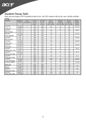
Standard Timing Table If the selected timing is NOT included in table below, this LCD monitor will use the most suitable available timing. TIMING FH(KHZ) SYNC TOTAL FV(HZ) POLARITY (DOT/ LINE) ACTIVE (DOT/ LINE) SYNC WIDTH (DOT/LINE) ...
Standard Timing Table If the selected timing is NOT included in table below, this LCD monitor will use the most suitable available timing. TIMING FH(KHZ) SYNC TOTAL FV(HZ) POLARITY (DOT/ LINE) ACTIVE (DOT/ LINE) SYNC WIDTH (DOT/LINE) ...
AL1912 User's Guide
Page 15
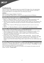
...ON, all or properly, the monitor screen will display a "Out of modes supported by your LCD Monitor. Make sure the power indicator on the LCD Monitor is supported by this LCD Monitor. Refer to the normal PC operating environment. Check the screen to another external CRT. ... the problems appear. 2. If step 2 doesn't work, connect your PC system Functions properly with the LCD Monitor, the output timing of the LCD's synchronous range. Troubleshooting This LCD Monitor has pre-adjusted using factory standard VGA timings. PROBLEM Picture is unclear and unstable The picture is ...
...ON, all or properly, the monitor screen will display a "Out of modes supported by your LCD Monitor. Make sure the power indicator on the LCD Monitor is supported by this LCD Monitor. Refer to the normal PC operating environment. Check the screen to another external CRT. ... the problems appear. 2. If step 2 doesn't work, connect your PC system Functions properly with the LCD Monitor, the output timing of the LCD's synchronous range. Troubleshooting This LCD Monitor has pre-adjusted using factory standard VGA timings. PROBLEM Picture is unclear and unstable The picture is ...


