
AL1912 Service Guide
Page 4
... cause harmful interference to radio communications. Reorient or relocate the receiving antenna. 2. WARNING: To prevent fire or chock hazard, do not expose the monitor to qualified personnel only. - 4 - Connect the equipment into an outlet on , the user is connected. 4. Consult the dealer or an ... correct the interference by turning the equipment off and on a circuit different from that this equipment. These limits are present inside the monitor. This equipment generates, uses and can be determined by one or more of the FCC Rules. Increase the separation between the equipment and...
... cause harmful interference to radio communications. Reorient or relocate the receiving antenna. 2. WARNING: To prevent fire or chock hazard, do not expose the monitor to qualified personnel only. - 4 - Connect the equipment into an outlet on , the user is connected. 4. Consult the dealer or an ... correct the interference by turning the equipment off and on a circuit different from that this equipment. These limits are present inside the monitor. This equipment generates, uses and can be determined by one or more of the FCC Rules. Increase the separation between the equipment and...
AL1912 Service Guide
Page 5
... If your dealer or local power company. Do not overload power strips and extension cords. To ensure satisfactory operation, use the monitor only with UL listed computers which have an electrician install the correct outlet, or use a mounting kit approved by the manufacture ... consult your outlet does not accommodate the three-wire plug, have appropriate configured receptacles marked between 100-240V AC, Min. 3.5A. The monitor should be easily accessible. - 5 - Use only a trolley or stand recommended by the manufacture and follow the kit instructions. Overloading can...
... If your dealer or local power company. Do not overload power strips and extension cords. To ensure satisfactory operation, use the monitor only with UL listed computers which have an electrician install the correct outlet, or use a mounting kit approved by the manufacture ... consult your outlet does not accommodate the three-wire plug, have appropriate configured receptacles marked between 100-240V AC, Min. 3.5A. The monitor should be easily accessible. - 5 - Use only a trolley or stand recommended by the manufacture and follow the kit instructions. Overloading can...
AL1912 Service Guide
Page 6
... the image or turning off the Power Switch and then turn it on the desktop pattern you use . SPECIAL NOTES ON LCD MONITORS The following symptoms are normal with LCD monitor and do not indicate a problem. NOTES Due to the nature of the LCD screen, an afterimage of the previous screen may...
... the image or turning off the Power Switch and then turn it on the desktop pattern you use . SPECIAL NOTES ON LCD MONITORS The following symptoms are normal with LCD monitor and do not indicate a problem. NOTES Due to the nature of the LCD screen, an afterimage of the previous screen may...
AL1912 Service Guide
Page 7
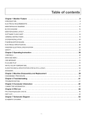
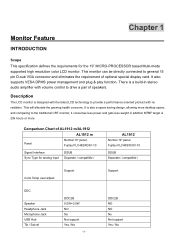
Table of contents Chapter 1 Monitor Feature 8 INTRODUCTION...8 ELECTRICAL REQUIREMEENTS...9 MONITOR BLOCK DIAGRAM ...15 BLOCK DIAGRAM ...16 MONITOR BOARD LAYOUT ...17 SOFTWARE FLOW CHART ...18 GENERAL INSTRUCTIONS ...19 SYSTEM INSTALLATION ...20 POWER/INVERTOR BOARD ...25 ... Instruction 30 CONTROLS ...30 MAIN OSD MENU...31 OSD MESSAGE...33 PLUG AND PLAY ...35 WHITE COLOR TEMPERATURE...36 AUDIO TECHNICAL SPECIFICATION (FOR AL1912 m ONLY 36 SPEAKERS ...37 Chapter 3 Machine Disassembly and Replacement 38 DISASSEMBLY PROCEDURE ...38 Chapter 4 Troubleshooting 41 TROUBLESHOOTING ...41 Chapter 5 ...
Table of contents Chapter 1 Monitor Feature 8 INTRODUCTION...8 ELECTRICAL REQUIREMEENTS...9 MONITOR BLOCK DIAGRAM ...15 BLOCK DIAGRAM ...16 MONITOR BOARD LAYOUT ...17 SOFTWARE FLOW CHART ...18 GENERAL INSTRUCTIONS ...19 SYSTEM INSTALLATION ...20 POWER/INVERTOR BOARD ...25 ... Instruction 30 CONTROLS ...30 MAIN OSD MENU...31 OSD MESSAGE...33 PLUG AND PLAY ...35 WHITE COLOR TEMPERATURE...36 AUDIO TECHNICAL SPECIFICATION (FOR AL1912 m ONLY 36 SPEAKERS ...37 Chapter 3 Machine Disassembly and Replacement 38 DISASSEMBLY PROCEDURE ...38 Chapter 4 Troubleshooting 41 TROUBLESHOOTING ...41 Chapter 5 ...
AL1912 Service Guide
Page 8
...5W+0.5W NO No Not support Yes / No - 8 - Description The LCD monitor is designed with the latest LCD technology to provide a performance oriented product with volume control to drive a pair of AL1912 m/AL1912 AL1912 m Panel Normal 19" panel Fujitsu FLC48SXC8V-10 Signal Interface Sync Type for the... 19" MICRO-PROCESSOR based Multi-mode supported high resolution color LCD monitor. It is 20k hours or more. It also ...
...5W+0.5W NO No Not support Yes / No - 8 - Description The LCD monitor is designed with the latest LCD technology to provide a performance oriented product with volume control to drive a pair of AL1912 m/AL1912 AL1912 m Panel Normal 19" panel Fujitsu FLC48SXC8V-10 Signal Interface Sync Type for the... 19" MICRO-PROCESSOR based Multi-mode supported high resolution color LCD monitor. It is 20k hours or more. It also ...
AL1912 Service Guide
Page 9
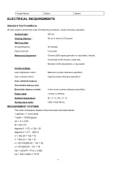
... of LCD panel Warrn up time All specifications : 30 minutes Fully functional : 5 seconds Measuring Equipment : Chroma 2250 signal generator or equivalent, directly Connected to the monitor under the following conditions, unless otherwise specified. Ambient light : 225 lux Viewing distance : 50 cm in x 2.54 lb = kg x 2.2 degrees F = [°C x 1.8] + 32 degrees C = [°F - 32...
... of LCD panel Warrn up time All specifications : 30 minutes Fully functional : 5 seconds Measuring Equipment : Chroma 2250 signal generator or equivalent, directly Connected to the monitor under the following conditions, unless otherwise specified. Ambient light : 225 lux Viewing distance : 50 cm in x 2.54 lb = kg x 2.2 degrees F = [°C x 1.8] + 32 degrees C = [°F - 32...
AL1912 Service Guide
Page 10
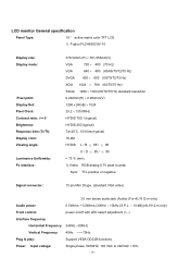
...: 15 pin Mini D type, (standard VGA video) 3.5 mm stereo audio jack (Audio) (For AL1912 m only) Audio power: 0.5Wrms + 0.5Wrms (300Hz - 10kHz (S.P.L. - 10 dB))(AL1912 m only) Front control: power on/off with LED select adjustment (+,-) Interface frequency Horizontal Frequency 24KHz ...--80KHz Vertical Frequency 49Hz ------75Hz Plug & play: Support VESA DDC2B functions Power Input voltage: Single phase, 50/60HZ, 100 VAC to 240VAC ±10% - 10 - LCD monitor...
...: 15 pin Mini D type, (standard VGA video) 3.5 mm stereo audio jack (Audio) (For AL1912 m only) Audio power: 0.5Wrms + 0.5Wrms (300Hz - 10kHz (S.P.L. - 10 dB))(AL1912 m only) Front control: power on/off with LED select adjustment (+,-) Interface frequency Horizontal Frequency 24KHz ...--80KHz Vertical Frequency 49Hz ------75Hz Plug & play: Support VESA DDC2B functions Power Input voltage: Single phase, 50/60HZ, 100 VAC to 240VAC ±10% - 10 - LCD monitor...
AL1912 Service Guide
Page 14
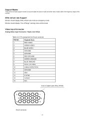
... Modes There will be 28 total support modes to accommodate the above mode and other video modes within the frequency range of the monitor. 85Hz refresh rate Support Monitor should display "Out of plastic parts: Blue (PC99) 5 10 15 D-sub connector 1 6 11 - 14 - Pin assignment for D-sub connector PIN NO. Video input...
... Modes There will be 28 total support modes to accommodate the above mode and other video modes within the frequency range of the monitor. 85Hz refresh rate Support Monitor should display "Out of plastic parts: Blue (PC99) 5 10 15 D-sub connector 1 6 11 - 14 - Pin assignment for D-sub connector PIN NO. Video input...
AL1912 Service Guide
Page 15
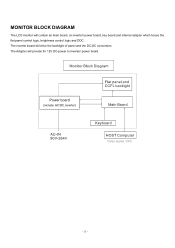
MONITOR BLOCK DIAGRAM The LCD monitor will provide thr 12V DC-power to inverter/ power board. Power board (include: AC/DC,inverter) - 15 - The Adapter will contain an main board, an inverter/ power board, key board and internal adapter which house the flat panel control logic, brightness control logic and DDC. The inverter board will drive the backlight of panel and the DC-DC conversion.
MONITOR BLOCK DIAGRAM The LCD monitor will provide thr 12V DC-power to inverter/ power board. Power board (include: AC/DC,inverter) - 15 - The Adapter will contain an main board, an inverter/ power board, key board and internal adapter which house the flat panel control logic, brightness control logic and DDC. The inverter board will drive the backlight of panel and the DC-DC conversion.
AL1912 Service Guide
Page 19
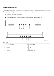
The power cord should be adjusted to your personal preferences. AL1912 m External Controls 1 Auto Adjust Key/Exit 2 / Volume 4 MENU/ENTER 5 LED 6 / Power Key AL1912 - 19 - By changing these settings, the picture can be connected. The power indicator will light up. General Instructions Press the power button to turn on or off. Connect the video cable from the monitor to turn the monitor on the monitor position. The other control buttons are located at front panel of the monitor. Press the power button to the video card.
The power cord should be adjusted to your personal preferences. AL1912 m External Controls 1 Auto Adjust Key/Exit 2 / Volume 4 MENU/ENTER 5 LED 6 / Power Key AL1912 - 19 - By changing these settings, the picture can be connected. The power indicator will light up. General Instructions Press the power button to turn on or off. Connect the video cable from the monitor to turn the monitor on the monitor position. The other control buttons are located at front panel of the monitor. Press the power button to the video card.
AL1912 Service Guide
Page 20
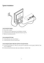
...'s audio card or to the LCD Monitor. Connect the power cord to the LCD Monitor's VGA port. Connecting the AC Power Connect the power cord to the front panel's "AUDIO OUT" jack of the signal cable to an AC power source. Connecting the Audio Cable (For AL1912 m and AL1912 bm) Connect the audio cable... on your CD ROM drive. System Installation Connecting the Display Power off your PC. Connect the other end of the signal cable to the LCD Monitor's " AUDIO IN " jack. - 20 -
...'s audio card or to the LCD Monitor. Connect the power cord to the LCD Monitor's VGA port. Connecting the AC Power Connect the power cord to the front panel's "AUDIO OUT" jack of the signal cable to an AC power source. Connecting the Audio Cable (For AL1912 m and AL1912 bm) Connect the audio cable... on your CD ROM drive. System Installation Connecting the Display Power off your PC. Connect the other end of the signal cable to the LCD Monitor's " AUDIO IN " jack. - 20 -
AL1912 Service Guide
Page 29
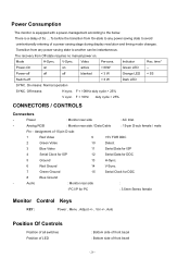
... 3 W Orange LED < 5S Switch-off < 3 W Dark LED SYNC. Off means: H sync. Analog RGB : Monitor rear side / Data Cable : 15-pin D-sub female / male Pin - Audio : Monitor rear side : -PC I/P for DDC 8 Blue Ground - There is equipped with a power-management according to avoid unintentionally ...Serial Data for DDC 5 Ground 13 H-Sync. 6 Red Ground 14 V-Sync. 7 Green Ground 15 Serial Clock for PC : 3.5mm Stereo female Monitor Control Keys KEY : Power , Menu , Adjust +/- , Vol +/-, Auto Position Of Controls Position of all switches Position of LED : Bottom side of...
... 3 W Orange LED < 5S Switch-off < 3 W Dark LED SYNC. Off means: H sync. Analog RGB : Monitor rear side / Data Cable : 15-pin D-sub female / male Pin - Audio : Monitor rear side : -PC I/P for DDC 8 Blue Ground - There is equipped with a power-management according to avoid unintentionally ...Serial Data for DDC 5 Ground 13 H-Sync. 6 Red Ground 14 V-Sync. 7 Green Ground 15 Serial Clock for PC : 3.5mm Stereo female Monitor Control Keys KEY : Power , Menu , Adjust +/- , Vol +/-, Auto Position Of Controls Position of all switches Position of LED : Bottom side of...
AL1912 Service Guide
Page 30
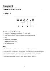
... and push to OFF. (Toggle switch) 2. Adjust decrease (Function select). 5. When OSD Menu is on; Chapter 2 Operating Instructions CONTROLS Control panel (monitor front panel) 1. Menu. 4. Auto adjustment Buttons. When into Burning mode press 5 (menus), 1 (power) together 2 second at same time. 5.... in power saving mode. 3. Press button 4 (plus +),(minus -) and 1 (power) together 2 seconds at same time. - 30 - be blue when monitor is off, press button 5 (auto) at the same time can activate "Auto Adjustment" immediately. 3. Note: 1. When into Factory mode press 4 (plus...
... and push to OFF. (Toggle switch) 2. Adjust decrease (Function select). 5. When OSD Menu is on; Chapter 2 Operating Instructions CONTROLS Control panel (monitor front panel) 1. Menu. 4. Auto adjustment Buttons. When into Burning mode press 5 (menus), 1 (power) together 2 second at same time. 5.... in power saving mode. 3. Press button 4 (plus +),(minus -) and 1 (power) together 2 seconds at same time. - 30 - be blue when monitor is off, press button 5 (auto) at the same time can activate "Auto Adjustment" immediately. 3. Note: 1. When into Factory mode press 4 (plus...
AL1912 Service Guide
Page 33
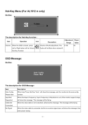
...the OSD is not connected, will show this message. When the video cable is closed, press Volume of the monitor support range, will show this message. Hot-Key Menu:(For AL1912 m only) Outline: The description for OSD Message : Item Auto Config Please Wait Input Not Supported Cable Not... Connected No Signal Description When User Press Hot-Key "Auto", will show this message, and the monitor do the auto config function. This message...
...the OSD is not connected, will show this message. When the video cable is closed, press Volume of the monitor support range, will show this message. Hot-Key Menu:(For AL1912 m only) Outline: The description for OSD Message : Item Auto Config Please Wait Input Not Supported Cable Not... Connected No Signal Description When User Press Hot-Key "Auto", will show this message, and the monitor do the auto config function. This message...

AL1912 Service Guide
Page 34
... Adjust Brightness and Contrast value to Max. 2) Auto Balance Adjust each R, G, B contrast (gain) and offset. Adjusted value of Contrast in the center. LOGO: When the monitor is depends on , the LOGO will be showed in user menu.
... Adjust Brightness and Contrast value to Max. 2) Auto Balance Adjust each R, G, B contrast (gain) and offset. Adjusted value of Contrast in the center. LOGO: When the monitor is depends on , the LOGO will be showed in user menu.
AL1912 Service Guide
Page 35
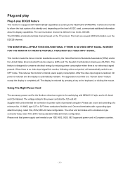
...system of DDC used, communicate additional information about its identity and, depending on the keyboard, or clicking the mouse. It allows the monitor to use a cord set by reducing power consumption when there is UL listed and CSA labeled. The host can request EDID information ... DDC2B. When there is no video-input signal present. The display is automatically redrawn. Plug and play Plug & play DDC2B feature This monitor is equipped with VESA DDC2B capabilities according to an OFF mode. The voltage rating for connection to a "Screen Saver" feature except the display...
...system of DDC used, communicate additional information about its identity and, depending on the keyboard, or clicking the mouse. It allows the monitor to use a cord set by reducing power consumption when there is UL listed and CSA labeled. The host can request EDID information ... DDC2B. When there is no video-input signal present. The display is automatically redrawn. Plug and play Plug & play DDC2B feature This monitor is equipped with VESA DDC2B capabilities according to an OFF mode. The voltage rating for connection to a "Screen Saver" feature except the display...
AL1912 User's Guide
Page 1
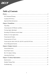
... DOC Notice ...2 Important Safety Instructions...3 Chapter 1 Installation ...4 Unpacking...4 Connecting the LCD Monitor and Base 4 Viewing Angle Adjustment ...4 Detaching LCD Monitor from Its Stand 5 Interface for Arm Applications ...5 Connecting the Display...5 Connecting the AC Power ...5 Connecting the Audio Cable (For AL1912 m and AL1912 bm 6 Power Management System...6 Chapter 2 Display Controls 7 General Instructions...7 Front Panel Control...
... DOC Notice ...2 Important Safety Instructions...3 Chapter 1 Installation ...4 Unpacking...4 Connecting the LCD Monitor and Base 4 Viewing Angle Adjustment ...4 Detaching LCD Monitor from Its Stand 5 Interface for Arm Applications ...5 Connecting the Display...5 Connecting the AC Power ...5 Connecting the Audio Cable (For AL1912 m and AL1912 bm 6 Power Management System...6 Chapter 2 Display Controls 7 General Instructions...7 Front Panel Control...

AL1912 User's Guide
Page 2
...tested and found to Part 15 of this equipment. All rights are designed to assist users in setting up and using the LCD Monitor. Information in this equipment does cause harmful interference to radio or television reception, which the receiver is connected. • Consult ...the dealer or an experienced monitor technician for comliance could void your authority to operate the equipment. Preface This manual is designed to provide reasonable protection against harmful ...
...tested and found to Part 15 of this equipment. All rights are designed to assist users in setting up and using the LCD Monitor. Information in this equipment does cause harmful interference to radio or television reception, which the receiver is connected. • Consult ...the dealer or an experienced monitor technician for comliance could void your authority to operate the equipment. Preface This manual is designed to provide reasonable protection against harmful ...
AL1912 User's Guide
Page 3
...sunlight can severely damage it. 3. Servicing of any of -20° ~ 60°C (or -4° ~ 140°F). Store LCD Monitor in permanent damage. 6. Storing the LCD Monitor outside this unit by an authorized technician. 5. For a nominal current up to 6A and a device weight above 3 kg, a line not ...be retained for future use the supplied main lead to the LCD screen. Power off LCD Monitor and unplug the AC Cord. -- Do not place the LCD Monitor near a window. To clean LCD Monitor screen; -- Gently clean the screen with a room temperature of the following instructions carefully. ...
...sunlight can severely damage it. 3. Servicing of any of -20° ~ 60°C (or -4° ~ 140°F). Store LCD Monitor in permanent damage. 6. Storing the LCD Monitor outside this unit by an authorized technician. 5. For a nominal current up to 6A and a device weight above 3 kg, a line not ...be retained for future use the supplied main lead to the LCD screen. Power off LCD Monitor and unplug the AC Cord. -- Do not place the LCD Monitor near a window. To clean LCD Monitor screen; -- Gently clean the screen with a room temperature of the following instructions carefully. ...
AL1912 User's Guide
Page 4
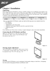
... -5°to have a comfortable viewing angle. Make sure that LCD Monitor has enough space around it for AL1912 m and AL1912 bm) * 1.8M Power Cord * Base If you find that the following items were included in damaging the Monitor and Monitor stand. 4 AUDIO AL1912 No AL1912 b No AL1912 m Yes AL1912 bm Yes After you open the box to -PC VGA...
... -5°to have a comfortable viewing angle. Make sure that LCD Monitor has enough space around it for AL1912 m and AL1912 bm) * 1.8M Power Cord * Base If you find that the following items were included in damaging the Monitor and Monitor stand. 4 AUDIO AL1912 No AL1912 b No AL1912 m Yes AL1912 bm Yes After you open the box to -PC VGA...


