
AL1912 Service Guide
Page 5
... removing covers can result in the back and bottom of the grounded plug. Do not overload power strips and extension cords. Never push any object into a grounded power outlet as a safety feature. To ensure satisfactory operation, use the monitor near the equipment and shall be used for ventilation. Use only a trolley or stand recommended by the manufacture and follow the kit instructions...
... removing covers can result in the back and bottom of the grounded plug. Do not overload power strips and extension cords. Never push any object into a grounded power outlet as a safety feature. To ensure satisfactory operation, use the monitor near the equipment and shall be used for ventilation. Use only a trolley or stand recommended by the manufacture and follow the kit instructions...
AL1912 Service Guide
Page 7
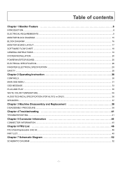
......9 MONITOR BLOCK DIAGRAM ...15 BLOCK DIAGRAM ...16 MONITOR BOARD LAYOUT ...17 SOFTWARE FLOW CHART ...18 GENERAL INSTRUCTIONS ...19 SYSTEM INSTALLATION ...20 POWER/INVERTOR BOARD ...25 ELECTRICAL SPECIFICATION...26 INVERTER ELECTRICAL SPECIFICATION ...28 SAFETY ...28 Chapter 2 Operating Instruction 30 CONTROLS ...30 MAIN OSD MENU...31 OSD MESSAGE...33 PLUG AND PLAY ...35 WHITE COLOR TEMPERATURE...36 AUDIO TECHNICAL SPECIFICATION (FOR AL1912 m ONLY 36 SPEAKERS ...37 Chapter 3 Machine Disassembly and Replacement 38 DISASSEMBLY PROCEDURE ...38 Chapter 4 Troubleshooting 41 TROUBLESHOOTING...
......9 MONITOR BLOCK DIAGRAM ...15 BLOCK DIAGRAM ...16 MONITOR BOARD LAYOUT ...17 SOFTWARE FLOW CHART ...18 GENERAL INSTRUCTIONS ...19 SYSTEM INSTALLATION ...20 POWER/INVERTOR BOARD ...25 ELECTRICAL SPECIFICATION...26 INVERTER ELECTRICAL SPECIFICATION ...28 SAFETY ...28 Chapter 2 Operating Instruction 30 CONTROLS ...30 MAIN OSD MENU...31 OSD MESSAGE...33 PLUG AND PLAY ...35 WHITE COLOR TEMPERATURE...36 AUDIO TECHNICAL SPECIFICATION (FOR AL1912 m ONLY 36 SPEAKERS ...37 Chapter 3 Machine Disassembly and Replacement 38 DISASSEMBLY PROCEDURE ...38 Chapter 4 Troubleshooting 41 TROUBLESHOOTING...
AL1912 Service Guide
Page 8
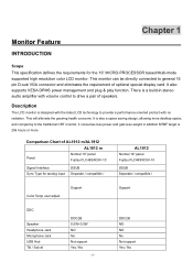
... product with volume control to general 15 pin D-sub VGA connector and eliminates the requirement of optional special display card. Comparison Chart of speakers. There is also a space saving design, allowing more . Monitor Feature INTRODUCTION Chapter 1 Scope This specification defines the requirements for analog input DSUB Separate / compatible / AL1912 Normal 19" panel Fujitsu FLC48SXC8V-10 DSUB Separate / compatible / Color Temp user adjust Support Support DDC Speaker Headphone Jack Microphone Jack USB Hub Tilt / Swivel...
... product with volume control to general 15 pin D-sub VGA connector and eliminates the requirement of optional special display card. Comparison Chart of speakers. There is also a space saving design, allowing more . Monitor Feature INTRODUCTION Chapter 1 Scope This specification defines the requirements for analog input DSUB Separate / compatible / AL1912 Normal 19" panel Fujitsu FLC48SXC8V-10 DSUB Separate / compatible / Color Temp user adjust Support Support DDC Speaker Headphone Jack Microphone Jack USB Hub Tilt / Swivel...
AL1912 Service Guide
Page 9
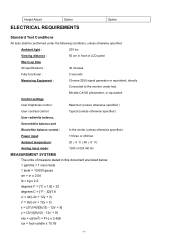
Minolta CA100 photometer, or equivalent Control settings User brightness control : Maximum (unless otherwise specified ) User contrast control: Typical (unless otherwise specified ) User red/white balance, Green/white balance and Blue/white balance control : In the center (unless otherwise specified ) Power input: 110Vac or 230Vac Ambient temperature: 20 ± 5 ˚C ( 68 ± 9 ˚ F) Analog input mode: 1280 x1024 /60 Hz MEASUREMENT SYSTEMS The units of measure stated in this document are listed below...
Minolta CA100 photometer, or equivalent Control settings User brightness control : Maximum (unless otherwise specified ) User contrast control: Typical (unless otherwise specified ) User red/white balance, Green/white balance and Blue/white balance control : In the center (unless otherwise specified ) Power input: 110Vac or 230Vac Ambient temperature: 20 ± 5 ˚C ( 68 ± 9 ˚ F) Analog input mode: 1280 x1024 /60 Hz MEASUREMENT SYSTEMS The units of measure stated in this document are listed below...
AL1912 Service Guide
Page 10
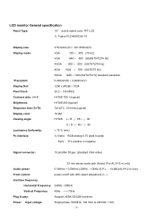
... Sync: TTL positive or negative Signal connector: 15 pin Mini D type, (standard VGA video) 3.5 mm stereo audio jack (Audio) (For AL1912 m only) Audio power: 0.5Wrms + 0.5Wrms (300Hz - 10kHz (S.P.L. - 10 dB))(AL1912 m only) Front control: power on/off with LED select adjustment (+,-) Interface frequency Horizontal Frequency 24KHz --80KHz Vertical Frequency 49Hz ------75Hz Plug & play: Support VESA DDC2B functions Power Input voltage: Single phase, 50/60HZ, 100 VAC to 240VAC ±10% - 10 - LCD monitor General specification Panel Type: 19 " active matrix color TFT LCD...
... Sync: TTL positive or negative Signal connector: 15 pin Mini D type, (standard VGA video) 3.5 mm stereo audio jack (Audio) (For AL1912 m only) Audio power: 0.5Wrms + 0.5Wrms (300Hz - 10kHz (S.P.L. - 10 dB))(AL1912 m only) Front control: power on/off with LED select adjustment (+,-) Interface frequency Horizontal Frequency 24KHz --80KHz Vertical Frequency 49Hz ------75Hz Plug & play: Support VESA DDC2B functions Power Input voltage: Single phase, 50/60HZ, 100 VAC to 240VAC ±10% - 10 - LCD monitor General specification Panel Type: 19 " active matrix color TFT LCD...
AL1912 Service Guide
Page 12
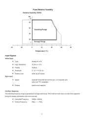
...timing the display optimization will not be assured. • Horizontal Frequency • Vertical Frequency 24KHz --80KHz 49Hz -------75Hz - 12 - Interface frequency The following frequency range is generalized by supported timing. Panel Relative Humidity Input Signals Video input • Type • Input Impedance • Polarity • Amplitude • Display Color Sync input • Signal • Polarity Analog R, G, B. 75 ohm +/- 2% Positive 0 - 0.7 +/- 0.05 Vp same as LCD panel separate horizontal and vertical sync, or composite sync which are TTL compatible positive and...
...timing the display optimization will not be assured. • Horizontal Frequency • Vertical Frequency 24KHz --80KHz 49Hz -------75Hz - 12 - Interface frequency The following frequency range is generalized by supported timing. Panel Relative Humidity Input Signals Video input • Type • Input Impedance • Polarity • Amplitude • Display Color Sync input • Signal • Polarity Analog R, G, B. 75 ohm +/- 2% Positive 0 - 0.7 +/- 0.05 Vp same as LCD panel separate horizontal and vertical sync, or composite sync which are TTL compatible positive and...
AL1912 Service Guide
Page 19
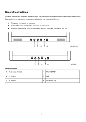
General Instructions Press the power button to the video card. Connect the video cable from the monitor to turn on or off. The other control buttons are located at front panel of the monitor. By changing these settings, the picture can be connected. The power cord should be adjusted to turn the monitor on the monitor position. The power indicator will light up. Press the power button to your personal preferences. AL1912 m External Controls 1 Auto Adjust Key/Exit 2 / Volume 4 MENU/ENTER 5 LED 6 / Power Key AL1912 - 19 -
General Instructions Press the power button to the video card. Connect the video cable from the monitor to turn on or off. The other control buttons are located at front panel of the monitor. By changing these settings, the picture can be connected. The power cord should be adjusted to turn the monitor on the monitor position. The power indicator will light up. Press the power button to your personal preferences. AL1912 m External Controls 1 Auto Adjust Key/Exit 2 / Volume 4 MENU/ENTER 5 LED 6 / Power Key AL1912 - 19 -
AL1912 Service Guide
Page 28
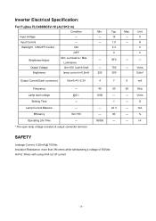
... Life Time --- *.The open lamp voltage is testes at output connector terminal 40 50 60 KHz 1600 --- --- Backlight ON/OFF Control ON OFF Brightness Adjust Min. Brightness lamp current in 6.5mA 250 Typ. 15 1.5 3.3 0 30% 750 300 Max. Lamp start voltage @0℃ Striking Time --- mA --- 80 --- % 50000 --- --- Input Current --- --- Inverter Electrical Specification: For Fujitsu FLC488SC8V-10 (AL1912 m) Condition Min. Input Voltage --- --- V --- Hr...
... Life Time --- *.The open lamp voltage is testes at output connector terminal 40 50 60 KHz 1600 --- --- Backlight ON/OFF Control ON OFF Brightness Adjust Min. Brightness lamp current in 6.5mA 250 Typ. 15 1.5 3.3 0 30% 750 300 Max. Lamp start voltage @0℃ Striking Time --- mA --- 80 --- % 50000 --- --- Input Current --- --- Inverter Electrical Specification: For Fujitsu FLC488SC8V-10 (AL1912 m) Condition Min. Input Voltage --- --- V --- Hr...
AL1912 Service Guide
Page 29
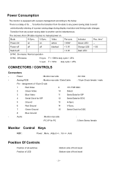
... 3 Blue Video 11 Serial Data for ISP 4 Serial Clock for ISP 12 Serial Data for DDC 5 Ground 13 H-Sync. 6 Red Ground 14 V-Sync. 7 Green Ground 15 Serial Clock for PC : 3.5mm Stereo female Monitor Control Keys KEY : Power , Menu , Adjust +/- , Vol +/-, Auto Position Of Controls Position of all switches Position of LED : Bottom side of front bezel : Bottom side of a power saving stage during display resolution and timing mode changes. On means: Normal operation SYNC. Analog RGB : Monitor rear side / Data Cable : 15...
... 3 Blue Video 11 Serial Data for ISP 4 Serial Clock for ISP 12 Serial Data for DDC 5 Ground 13 H-Sync. 6 Red Ground 14 V-Sync. 7 Green Ground 15 Serial Clock for PC : 3.5mm Stereo female Monitor Control Keys KEY : Power , Menu , Adjust +/- , Vol +/-, Auto Position Of Controls Position of all switches Position of LED : Bottom side of front bezel : Bottom side of a power saving stage during display resolution and timing mode changes. On means: Normal operation SYNC. Analog RGB : Monitor rear side / Data Cable : 15...
AL1912 Service Guide
Page 32
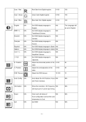
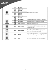
...;体中文 N/A 日本語 N/A H. Position OSD Timeout Auto Config N/A Information N/A Reset N/A Exit N/A Red Gain from Digital-register. 0-100 Green Gain Digital-register. 0-100 Blue Gain from Digital-register. 0-100 Set OSD display language to N/A Tranditional Chinese. Set OSD display language to N/A English. Set OSD display language to Italian. N/A Set OSD display language to Spain. Show the resolution, H/V frequency N/A and input port of the 0-100 OSD. Clear each old status of N/A Auto-configuration and set to Cool.
...;体中文 N/A 日本語 N/A H. Position OSD Timeout Auto Config N/A Information N/A Reset N/A Exit N/A Red Gain from Digital-register. 0-100 Green Gain Digital-register. 0-100 Blue Gain from Digital-register. 0-100 Set OSD display language to N/A Tranditional Chinese. Set OSD display language to N/A English. Set OSD display language to Italian. N/A Set OSD display language to Spain. Show the resolution, H/V frequency N/A and input port of the 0-100 OSD. Clear each old status of N/A Auto-configuration and set to Cool.
AL1912 Service Guide
Page 33
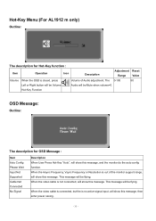
... Audio adjustment. This message will be Mute when volume=0. The 0-100 50 Left or Right button will be Volume Audio will be flying. This message will show this message, and the monitor do the auto config function. Hot-Key Menu:(For AL1912 m only) Outline: The description for OSD Message : Item Auto Config Please Wait Input Not Supported Cable Not Connected No Signal Description When User Press Hot-Key "Auto...
... Audio adjustment. This message will be Mute when volume=0. The 0-100 50 Left or Right button will be Volume Audio will be flying. This message will show this message, and the monitor do the auto config function. Hot-Key Menu:(For AL1912 m only) Outline: The description for OSD Message : Item Auto Config Please Wait Input Not Supported Cable Not Connected No Signal Description When User Press Hot-Key "Auto...
AL1912 Service Guide
Page 35
... display capabilities. Please note that power supply card needs to inform the host system of DDC used, communicate additional information about its identity and, depending on type connector body, rated 10A, 250V, having standard CEE-22 female configuration. It allows the monitor to use a cord set by reducing power consumption when there is no video input signal this monitor, following a time-out period, will automatically switch to the VESA...
... display capabilities. Please note that power supply card needs to inform the host system of DDC used, communicate additional information about its identity and, depending on type connector body, rated 10A, 250V, having standard CEE-22 female configuration. It allows the monitor to use a cord set by reducing power consumption when there is no video input signal this monitor, following a time-out period, will automatically switch to the VESA...
AL1912 User's Guide
Page 1
... Safety Instructions...3 Chapter 1 Installation ...4 Unpacking...4 Connecting the LCD Monitor and Base 4 Viewing Angle Adjustment ...4 Detaching LCD Monitor from Its Stand 5 Interface for Arm Applications ...5 Connecting the Display...5 Connecting the AC Power ...5 Connecting the Audio Cable (For AL1912 m and AL1912 bm 6 Power Management System...6 Chapter 2 Display Controls 7 General Instructions...7 Front Panel Control ...8 How To Adjust A Setting ...9 Adjusting The Picture ...9 Chapter 3 Technical Information 11 Specifications...11 Standard Timing Table ...13 Troubleshooting...15...
... Safety Instructions...3 Chapter 1 Installation ...4 Unpacking...4 Connecting the LCD Monitor and Base 4 Viewing Angle Adjustment ...4 Detaching LCD Monitor from Its Stand 5 Interface for Arm Applications ...5 Connecting the Display...5 Connecting the AC Power ...5 Connecting the Audio Cable (For AL1912 m and AL1912 bm 6 Power Management System...6 Chapter 2 Display Controls 7 General Instructions...7 Front Panel Control ...8 How To Adjust A Setting ...9 Adjusting The Picture ...9 Chapter 3 Technical Information 11 Specifications...11 Standard Timing Table ...13 Troubleshooting...15...
AL1912 User's Guide
Page 7
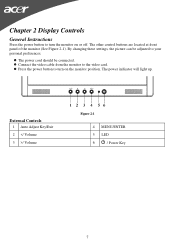
The other control buttons are located at front panel of the monitor (See Figure 2-1). Press the power button to turn the monitor on the monitor position. External Controls 1 Auto Adjust Key/Exit 2 / Volume Figure 2-1 4 MENU/ENTER 5 LED 6 / Power Key 7 Connect the video cable from the monitor to your personal preferences. The power cord should be adjusted to the video card. By changing these settings, the picture can be connected. The power indicator will light up. Chapter 2 Display Controls General Instructions Press the power button to turn on or off.
The other control buttons are located at front panel of the monitor (See Figure 2-1). Press the power button to turn the monitor on the monitor position. External Controls 1 Auto Adjust Key/Exit 2 / Volume Figure 2-1 4 MENU/ENTER 5 LED 6 / Power Key 7 Connect the video cable from the monitor to your personal preferences. The power cord should be adjusted to the video card. By changing these settings, the picture can be connected. The power indicator will light up. Chapter 2 Display Controls General Instructions Press the power button to turn on or off.
AL1912 User's Guide
Page 8
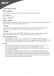
... sources such as it . 8 Power Indicator: Green - Stubborn stains may be removed with a cloth lightly dampened with a soft cloth. As a safety precaution, always unplug the monitor before cleaning it was originally packed at the factory. The Auto Adjustment function is in off mode MENU / ENTER : Activate OSD menu when OSD is OFF or activate/de-activate adjustment function when OSD is ON or Exit OSD menu when in Volume Adjust OSD status. /Volume...
... sources such as it . 8 Power Indicator: Green - Stubborn stains may be removed with a cloth lightly dampened with a soft cloth. As a safety precaution, always unplug the monitor before cleaning it was originally packed at the factory. The Auto Adjustment function is in off mode MENU / ENTER : Activate OSD menu when OSD is OFF or activate/de-activate adjustment function when OSD is ON or Exit OSD menu when in Volume Adjust OSD status. /Volume...
AL1912 User's Guide
Page 9
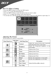
... want to adjust. 4. Adjusting The Picture The descriptions for function control LEDS Main Menu Icon Sub Menu Icon Sub Menu Item Contrast Brightness Description Adjusts the contrast between the foreground and background of the screen image. If you want to change the settings of the current function. 5. Press < or > to warm white. Position Adjust picture Focus V. User / Green Adjusts Red/Green/Blue intensity. Press the MENU-button to cool white. How To Adjust A Setting 1. Set the color temperature to activate the OSD window. 2. Press < or...
... want to adjust. 4. Adjusting The Picture The descriptions for function control LEDS Main Menu Icon Sub Menu Icon Sub Menu Item Contrast Brightness Description Adjusts the contrast between the foreground and background of the screen image. If you want to change the settings of the current function. 5. Press < or > to warm white. Position Adjust picture Focus V. User / Green Adjusts Red/Green/Blue intensity. Press the MENU-button to cool white. How To Adjust A Setting 1. Set the color temperature to activate the OSD window. 2. Press < or...
AL1912 User's Guide
Page 10
... Timeout Adjust the OSD timeout. N/A Information Show the resolution, H/V frequency and input port of the OSD. Position Adjust the vertical position of current iput timing. N/A Reset Clear each old status of picture. N/A Auto Config Auto Adjust the H/V Position, Focus and Clock of Auto-configuration and set the color temperature to Cool. V. N/A Exit Save user adjustment and OSD disappear. 10 N/A English N/A N/A Deutsch N/A Français N/A Español N/A Italiano N/A 简 N/A H. Position Multi-language selection. Adjust the horizontal position of the OSD...
... Timeout Adjust the OSD timeout. N/A Information Show the resolution, H/V frequency and input port of the OSD. Position Adjust the vertical position of current iput timing. N/A Reset Clear each old status of picture. N/A Auto Config Auto Adjust the H/V Position, Focus and Clock of Auto-configuration and set the color temperature to Cool. V. N/A Exit Save user adjustment and OSD disappear. 10 N/A English N/A N/A Deutsch N/A Français N/A Español N/A Italiano N/A 简 N/A H. Position Multi-language selection. Adjust the horizontal position of the OSD...
AL1912 User's Guide
Page 11
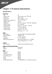
...(typical) Vertical: -85° ~ +85° Horizontal: -85° ~ +85° Video Input Signal Input Impedance Polarity Amplitude Multi-mode Supported Analogue RGB 0.7Vp-p/Digital TMDS 75 Ohm ± 2% Positive, Negative 0 - 0.7 ± 0.05 Vp Horizontal Frequency: 24 ~ 80 KHz Vertical Frequency: 49 ~ 75 Hz Control Power switch On/Off switch with LED indicator Audio (AL1912 m/AL1912 bm) Input 500mVrms Output 1W+1W OSD Brightness Contrast Horizontal Position Vertical Position Phase Clock Display Mode Setup Digital Digital Digital Digital Digital Digital Use EEPROM to save settings in...
...(typical) Vertical: -85° ~ +85° Horizontal: -85° ~ +85° Video Input Signal Input Impedance Polarity Amplitude Multi-mode Supported Analogue RGB 0.7Vp-p/Digital TMDS 75 Ohm ± 2% Positive, Negative 0 - 0.7 ± 0.05 Vp Horizontal Frequency: 24 ~ 80 KHz Vertical Frequency: 49 ~ 75 Hz Control Power switch On/Off switch with LED indicator Audio (AL1912 m/AL1912 bm) Input 500mVrms Output 1W+1W OSD Brightness Contrast Horizontal Position Vertical Position Phase Clock Display Mode Setup Digital Digital Digital Digital Digital Digital Use EEPROM to save settings in...
AL1912 User's Guide
Page 12
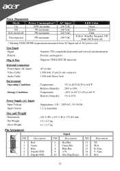
... VAC 240 VAC 240 VAC 240 VAC LED Color Green Yellow Dark Yellow: Standby, Suspend, Off Dark: DC Power off * Meeting VESA DPMS requirements measured from AC Input end of AC power cord. Sync Input Signal Polarity Plug & Play Separate TTL compatible horizontal and vertical synchronization Positive and negative Supports VESA DDC2B functions External Connection Power Input (AC input) Video Cable Audio Cable AC socket 1.8M with 15-pin D-sub connector 1.8M with Stereo Jack Environment Operating...
... VAC 240 VAC 240 VAC 240 VAC LED Color Green Yellow Dark Yellow: Standby, Suspend, Off Dark: DC Power off * Meeting VESA DPMS requirements measured from AC Input end of AC power cord. Sync Input Signal Polarity Plug & Play Separate TTL compatible horizontal and vertical synchronization Positive and negative Supports VESA DDC2B functions External Connection Power Input (AC input) Video Cable Audio Cable AC socket 1.8M with 15-pin D-sub connector 1.8M with Stereo Jack Environment Operating...
AL1912 User's Guide
Page 15
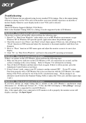
... OSD will display a message "No Input Signal". 15 PROBLEM There is outside of Range" message. Make sure the power indicator on timing. 2. If step 2 doesn't work, connect your PC system Functions properly with a CRT Monitor but it back on LCD Monitor If there's no picture, press the Adjustment Control button several times. 3. Choose a mode that is no picture on again. Also, if the signal cable is supported by this LCD Monitor. In Windows XP open the specific application...
... OSD will display a message "No Input Signal". 15 PROBLEM There is outside of Range" message. Make sure the power indicator on timing. 2. If step 2 doesn't work, connect your PC system Functions properly with a CRT Monitor but it back on LCD Monitor If there's no picture, press the Adjustment Control button several times. 3. Choose a mode that is no picture on again. Also, if the signal cable is supported by this LCD Monitor. In Windows XP open the specific application...


