
English Manual
Page 2
Remove the PART IDENTIFICATION CHART and the PART LIST/EXPLODED DRAWING before beginning assembly. WEIDER is not responsible or liable for commercial or rental purposes, or products used for indirect, special or consequential damages arising out of or in ...the date of purchase. ICON HEALTH & FITNESS, INC., 1500 S. 1000 W., LOGAN, UT 84321-9813 2 TABLE OF CONTENTS LIMITED WARRANTY IMPORTANT PRECAUTIONS BEFORE YOU BEGIN ASSEMBLY HOW TO USE THE HOME GYM SYSTEM WEIGHT RESISTANCE CHART TROUBLE-SHOOTING AND MAINTENANCE CABLE DIAGRAMS ORDERING REPLACEMENT PARTS 2 3 4 5 24 26 27 29 Back Cover...
Remove the PART IDENTIFICATION CHART and the PART LIST/EXPLODED DRAWING before beginning assembly. WEIDER is not responsible or liable for commercial or rental purposes, or products used for indirect, special or consequential damages arising out of or in ...the date of purchase. ICON HEALTH & FITNESS, INC., 1500 S. 1000 W., LOGAN, UT 84321-9813 2 TABLE OF CONTENTS LIMITED WARRANTY IMPORTANT PRECAUTIONS BEFORE YOU BEGIN ASSEMBLY HOW TO USE THE HOME GYM SYSTEM WEIGHT RESISTANCE CHART TROUBLE-SHOOTING AND MAINTENANCE CABLE DIAGRAMS ORDERING REPLACEMENT PARTS 2 3 4 5 24 26 27 29 Back Cover...
English Manual
Page 4
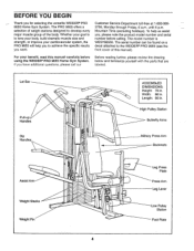
... WEIDER® PRO 9655 Home Gym System. Mountain Time (excluding holidays). The PRO 9655 offers a selection of weight stations designed to the WEIDER® PRO 9655 (see the front cover of the body. The serial number can be found on a decal attached to develop every major muscle group of this manual carefully before calling. it* E-rift a • • O ASSEMBLED...
... WEIDER® PRO 9655 Home Gym System. Mountain Time (excluding holidays). The PRO 9655 offers a selection of weight stations designed to the WEIDER® PRO 9655 (see the front cover of the body. The serial number can be found on a decal attached to develop every major muscle group of this manual carefully before calling. it* E-rift a • • O ASSEMBLED...
English Manual
Page 5
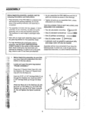
...for each stage is packaged separately. • Wait until assembly is completed. • The assembly is not in the parts bag, check to see if it has been pre-attached. • As you assemble the PRO 9655 be more convenient if you have the following information and instructions... parts as shown in the drawings. • Tighten all parts of the PRO 9655 in a cleared area and remove the packing materials; ASSEMBLY Before beginning assembly, carefully read and understand the infor- 1 mation in assembly, use the PART IDENTIFICATION CHART located In the center of this manual.
...for each stage is packaged separately. • Wait until assembly is completed. • The assembly is not in the parts bag, check to see if it has been pre-attached. • As you assemble the PRO 9655 be more convenient if you have the following information and instructions... parts as shown in the drawings. • Tighten all parts of the PRO 9655 in a cleared area and remove the packing materials; ASSEMBLY Before beginning assembly, carefully read and understand the infor- 1 mation in assembly, use the PART IDENTIFICATION CHART located In the center of this manual.
English Manual
Page 8
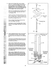
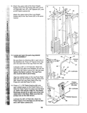
... bracket on the Base (4) as shown. Insert both Short Weight Guides (73) through the Weight Bumpers (19) and the bracket on the Base (4) as shown. Assemble the other Top Weight (65), Weight Cover (71) and Weight Tube (63) in the Weight Tube must be aligned. Slide fourteen Weights (25) onto the...
... bracket on the Base (4) as shown. Insert both Short Weight Guides (73) through the Weight Bumpers (19) and the bracket on the Base (4) as shown. Assemble the other Top Weight (65), Weight Cover (71) and Weight Tube (63) in the Weight Tube must be aligned. Slide fourteen Weights (25) onto the...
English Manual
Page 10
...). Attach the Leg Press Arm (96) to the Base (4) with the Bolt and a 3/8" Nylon Locknut (21). 12. Locate and open the parts bag labeled "ARM ASSEMBLY." 13 Be sure there is a Bushing (98) in the Base. Lubricate a 3/8" x 3 1/4" Bolt (67). cated tube in each end of the indi- Make sure that the...
...). Attach the Leg Press Arm (96) to the Base (4) with the Bolt and a 3/8" Nylon Locknut (21). 12. Locate and open the parts bag labeled "ARM ASSEMBLY." 13 Be sure there is a Bushing (98) in the Base. Lubricate a 3/8" x 3 1/4" Bolt (67). cated tube in each end of the indi- Make sure that the...
English Manual
Page 11
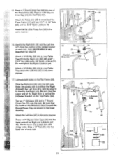
... Arm (48) and the Left Arm (47). Lubricate both axles on the Top Frame (55). Attach the Left Arm (47) in the same manner. 16. Assemble the other Press Arm (46) in the same manner. Note: Be careful not to confuse the Right Arm with a 3/8" x 2 1/2" Bolt (86) and a 3/8" Nylon Locknut (21...
... Arm (48) and the Left Arm (47). Lubricate both axles on the Top Frame (55). Attach the Left Arm (47) in the same manner. 16. Assemble the other Press Arm (46) in the same manner. Note: Be careful not to confuse the Right Arm with a 3/8" x 2 1/2" Bolt (86) and a 3/8" Nylon Locknut (21...
English Manual
Page 13
...Cable around a 3 1/2" Pulley (15). Before beginning this manual to the Top Frame (55) with two 5/16" x 2 3/4" Bolts (11) and two 5/16" Nylon Locknuts (3). IMPORTANT: While assembling the cables, do not overtighten the bolts and nuts attaching the pulleys. Locate and open the parts bags labeled "CABLE... ASSEMBLY" and "PULLEYS." During steps 19 through 39, refer to the Assist Upright (74) with a 3/8" x 3 3/4" Bolt (88) and a 3/8" Nylon Locknut (21). Be sure that the ...
...Cable around a 3 1/2" Pulley (15). Before beginning this manual to the Top Frame (55) with two 5/16" x 2 3/4" Bolts (11) and two 5/16" Nylon Locknuts (3). IMPORTANT: While assembling the cables, do not overtighten the bolts and nuts attaching the pulleys. Locate and open the parts bags labeled "CABLE... ASSEMBLY" and "PULLEYS." During steps 19 through 39, refer to the Assist Upright (74) with a 3/8" x 3 3/4" Bolt (88) and a 3/8" Nylon Locknut (21). Be sure that the ...

English Manual
Page 15
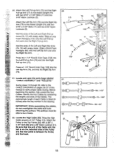
... Bolt. Be sure that the Cable and Pulley move smoothly. 27 66 21 57 28. Wrap the High Cable (58) around a 3 1/2" Pulley (15). Note: This assembly step shows how to the bracket on the outside of several pre- 29 attached parts. Reattach the 3 1/2" Low Pulley (102), with a 3/8" x 2" Bolt (12) and ... Frame (17). Remove the 3/8" Nylon Locknut (21), the Spacer, and the Pulley from the 3/8" x 3 3/4" Bolt (88). 27. Note: This may come pre-assembled. Be sure that the Cable and Pulley move smoothly. 28 55 0 58 15 12 57 Bracket 58 15 58 12 15 21 29. Attach a 3 1/2" Pulley...
... Bolt. Be sure that the Cable and Pulley move smoothly. 27 66 21 57 28. Wrap the High Cable (58) around a 3 1/2" Pulley (15). Note: This assembly step shows how to the bracket on the outside of several pre- 29 attached parts. Reattach the 3 1/2" Low Pulley (102), with a 3/8" x 2" Bolt (12) and ... Frame (17). Remove the 3/8" Nylon Locknut (21), the Spacer, and the Pulley from the 3/8" x 3 3/4" Bolt (88). 27. Note: This may come pre-assembled. Be sure that the Cable and Pulley move smoothly. 28 55 0 58 15 12 57 Bracket 58 15 58 12 15 21 29. Attach a 3 1/2" Pulley...

English Manual
Page 21
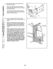
... Arm (105) with a 1/4" x 2 1/2" Screw (43) and a 1/4" Flat Washer (10). 85 56 A 37 92 18 43 10 2 44. Locate and open the parts bag labeled "SEAT ASSEMBLY." 43 0 Insert a 1/4" x 2 1/2" Carriage Bolt (92) through the indicated hole in a Seat Plate (37). 43.
... Arm (105) with a 1/4" x 2 1/2" Screw (43) and a 1/4" Flat Washer (10). 85 56 A 37 92 18 43 10 2 44. Locate and open the parts bag labeled "SEAT ASSEMBLY." 43 0 Insert a 1/4" x 2 1/2" Carriage Bolt (92) through the indicated hole in a Seat Plate (37). 43.
English Manual
Page 23
... Pad (30) onto each cable a few times to the home gym system as 51 shown. Make sure that the cables move smoothly, find and cor- ASSEMBLY 50. Before using the home gym system, pull each end of the cables does not move smoothly over the pulleys. If one of the Pad... the CABLE DIAGRAMS on pages 27 and 28. 36 30 34 28 34 30 0 29 0 PRO 9655 0 0 23 NANCE on pages 29 and 30 of this manual for proper cable routing. Remove the backing from the PRO 9655 decal and apply it by tightening the cables. If there is any slack in HOW TO...
... Pad (30) onto each cable a few times to the home gym system as 51 shown. Make sure that the cables move smoothly, find and cor- ASSEMBLY 50. Before using the home gym system, pull each end of the cables does not move smoothly over the pulleys. If one of the Pad... the CABLE DIAGRAMS on pages 27 and 28. 36 30 34 28 34 30 0 29 0 PRO 9655 0 0 23 NANCE on pages 29 and 30 of this manual for proper cable routing. Remove the backing from the PRO 9655 decal and apply it by tightening the cables. If there is any slack in HOW TO...
English Manual
Page 29
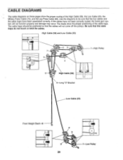
If the cables have been assembled correctly. CABLE DIAGRAMS The cable diagrams on these pages show the proper positioning of the High Cable (58), the Low Cable (23), the Military Press ...
If the cables have been assembled correctly. CABLE DIAGRAMS The cable diagrams on these pages show the proper positioning of the High Cable (58), the Low Cable (23), the Military Press ...
English Manual
Page 33
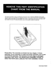
...quantity needed for shipping purposes. WESY96550 R0996A If you identify the small parts used in assembly. The number in the parts bags, check to see if it has been pre-assembled. Please Note: The assembly is packaged separately. The hardware for each part refers to the key number of ... This chart is provided to help'you cannot find a part in parenthesis below each stage is divided into four stages: 1) frame assembly, 2) arm assembly, 3) cable and pulley assembly, and 4) seat and backrest assembly. WAIT UNTIL YOU BEGIN EACH ASSEMBLY STAGE TO OPEN THE PARTS BAG LABELED FOR THAT...
...quantity needed for shipping purposes. WESY96550 R0996A If you identify the small parts used in assembly. The number in the parts bags, check to see if it has been pre-assembled. Please Note: The assembly is packaged separately. The hardware for each part refers to the key number of ... This chart is provided to help'you cannot find a part in parenthesis below each stage is divided into four stages: 1) frame assembly, 2) arm assembly, 3) cable and pulley assembly, and 4) seat and backrest assembly. WAIT UNTIL YOU BEGIN EACH ASSEMBLY STAGE TO OPEN THE PARTS BAG LABELED FOR THAT...


