
English Manual
Page 1
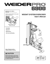
WEIGHT SYSTEM EXERCISER User’'s Manual Serial Number Decal (under the seat) •• Assembly •• Operation •• Maintenance •• Part List and Drawing Sears, Roebuck and Co. Hoffman Estates, IL 60179 CAUTION Read all precautions and instructions in the space above for future reference. Keep this equipment. Write the serial number in this manual before using this manual for reference. Model No. 831.14922.2 Serial No.
WEIGHT SYSTEM EXERCISER User’'s Manual Serial Number Decal (under the seat) •• Assembly •• Operation •• Maintenance •• Part List and Drawing Sears, Roebuck and Co. Hoffman Estates, IL 60179 CAUTION Read all precautions and instructions in the space above for future reference. Keep this equipment. Write the serial number in this manual before using this manual for reference. Model No. 831.14922.2 Serial No.

English Manual
Page 2
TABLE OF CONTENTS WARNING DECAL PLACEMENT 2 IMPORTANT PRECAUTIONS 3 BEFORE YOU BEGIN 4 PART IDENTIFICATION CHART 5 ASSEMBLY 6 ADJUSTMENT 21 WEIGHT RESISTANCE CHART 23 CABLE DIAGRAM 24 MAINTENANCE 25 EXERCISE GUIDELINES 26 PART LIST 29 EXPLODED DRAWING 30 ORDERING REPLACEMENT PARTS Back Cover 90 DAY FULL ...
TABLE OF CONTENTS WARNING DECAL PLACEMENT 2 IMPORTANT PRECAUTIONS 3 BEFORE YOU BEGIN 4 PART IDENTIFICATION CHART 5 ASSEMBLY 6 ADJUSTMENT 21 WEIGHT RESISTANCE CHART 23 CABLE DIAGRAM 24 MAINTENANCE 25 EXERCISE GUIDELINES 26 PART LIST 29 EXPLODED DRAWING 30 ORDERING REPLACEMENT PARTS Back Cover 90 DAY FULL ...
English Manual
Page 3
... PRECAUTIONS WARNING: To reduce the risk of serious injury, read all important precautions and instructions in this manual. 4. system. Always secure the weight stack with the lock pin and the lock after exercising to ensure that the cables are raised. Always stand on the foot plate when performing...personal injury or property damage sustained by persons weighing more than 300 lbs. (136 kg). 9. Do not use of this product. 1. The weight system should not be used by or through the use only. ICON assumes no responsibility for persons over age 35 or persons with great force...
... PRECAUTIONS WARNING: To reduce the risk of serious injury, read all important precautions and instructions in this manual. 4. system. Always secure the weight stack with the lock pin and the lock after exercising to ensure that the cables are raised. Always stand on the foot plate when performing...personal injury or property damage sustained by persons weighing more than 300 lbs. (136 kg). 9. Do not use of this product. 1. The weight system should not be used by or through the use only. ICON assumes no responsibility for persons over age 35 or persons with great force...

English Manual
Page 4
... designed to achieve the specic results you , note the product model number and serial number before using the weight system. For your cardiovascular system, the weight system will help us . The weight system offers a selection of the body. Height: 6 ft. 11 in. (211 cm) Width: 3 ft. 7 in. ... Weight Weight Pin Seat Note: The terms “"right side”" and “"left side”" are labeled. BEFORE YOU BEGIN Thank you have questions after reading this manual, please see the front cover of this manual. If you for selecting the versatile WEIDER PRO® 6900 weight ...
... designed to achieve the specic results you , note the product model number and serial number before using the weight system. For your cardiovascular system, the weight system will help us . The weight system offers a selection of the body. Height: 6 ft. 11 in. (211 cm) Width: 3 ft. 7 in. ... Weight Weight Pin Seat Note: The terms “"right side”" and “"left side”" are labeled. BEFORE YOU BEGIN Thank you have questions after reading this manual, please see the front cover of this manual. If you for selecting the versatile WEIDER PRO® 6900 weight ...
English Manual
Page 6
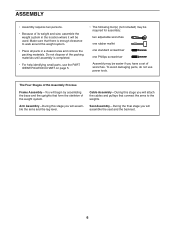
...151;-During this stage you will begin by assembling the base and the uprights that form the skeleton of the weight system. Make sure that connect the arms to walk around the weight system. •• Place all parts in the location where it will assemble the seat and the backrest.... 6 ASSEMBLY •• Assembly requires two persons. •• Because of its weight and size, assemble the weight system in a cleared area and remove the packing materials. Seat Assembly—-During the final stage you will be easier if you will...
...151;-During this stage you will begin by assembling the base and the uprights that form the skeleton of the weight system. Make sure that connect the arms to walk around the weight system. •• Place all parts in the location where it will assemble the seat and the backrest.... 6 ASSEMBLY •• Assembly requires two persons. •• Because of its weight and size, assemble the weight system in a cleared area and remove the packing materials. Seat Assembly—-During the final stage you will be easier if you will...

English Manual
Page 7
Do not overtighten the Locknut; Attach the Weight Guides (21) and the Base 2 (1) to the Base (1) with two M10 x 67mm Bolts (71), two M10 Washers (57), and two M10 Locknuts (56). the Foot Plate must pivot easily. 56 1 72 38 2. Do not tighten the Locknuts yet. 21 2 71 1 71 57 56 57 7 Attach the Foot Plate (38) to the Stabilizer (2) with an M10 x 130mm Bolt (72) and an M10 Locknut (56). Frame Assembly 1 1.
Do not overtighten the Locknut; Attach the Weight Guides (21) and the Base 2 (1) to the Base (1) with two M10 x 67mm Bolts (71), two M10 Washers (57), and two M10 Locknuts (56). the Foot Plate must pivot easily. 56 1 72 38 2. Do not tighten the Locknuts yet. 21 2 71 1 71 57 56 57 7 Attach the Foot Plate (38) to the Stabilizer (2) with an M10 x 130mm Bolt (72) and an M10 Locknut (56). Frame Assembly 1 1.

English Manual
Page 9
...) so that the pin on the bottom as shown. Slide the Weights onto the Weight Guides (21). Then, slide the Weight onto the Weight Guides (21). 21 22 Grease 22 Pin Hole Pin 24 27 9 Insert the Weight Selector (24) into the nine Weights (22). Do not tighten the Locknuts yet. Attach the Seat Tube (6) to... 5 two M8 x 65mm Bolts (68), two M8 Washers (59), and two M8 Locknuts (58). Attach the Seat Tube (6) to the Front Leg (7) in the remaining Weight (22). Apply some of the included grease inside the indicated holes in the same way. 6 7 59 58 3 68 68 68 68 58 59 6.
...) so that the pin on the bottom as shown. Slide the Weights onto the Weight Guides (21). Then, slide the Weight onto the Weight Guides (21). 21 22 Grease 22 Pin Hole Pin 24 27 9 Insert the Weight Selector (24) into the nine Weights (22). Do not tighten the Locknuts yet. Attach the Seat Tube (6) to... 5 two M8 x 65mm Bolts (68), two M8 Washers (59), and two M8 Locknuts (58). Attach the Seat Tube (6) to the Front Leg (7) in the remaining Weight (22). Apply some of the included grease inside the indicated holes in the same way. 6 7 59 58 3 68 68 68 68 58 59 6.

English Manual
Page 10
... bracket on the Front Leg. 76 Grease 7 8 76 10 Do not tighten the Screws yet. Do not tighten the Locknuts yet. See steps 2 to the Weight Guides (21) with an M4 x 20mm Self-tapping Screw (69) and an M4 Washer (33). Attach the Top Frame (4) to 7. Attach the Leg Bumper (60...
... bracket on the Front Leg. 76 Grease 7 8 76 10 Do not tighten the Screws yet. Do not tighten the Locknuts yet. See steps 2 to the Weight Guides (21) with an M4 x 20mm Self-tapping Screw (69) and an M4 Washer (33). Attach the Top Frame (4) to 7. Attach the Leg Bumper (60...

English Manual
Page 18
... the Seat Tube and one of the holes in the Seat Frame. 30. Tighten the High Cable (55) into the Upright and one of the Weight Selector (24). Attach the Backrest (16) to the Seat Frame (73) with two M6 x 16mm Screws (62), an M6 x 32mm Screw (64), and an M6... Washer (82). 16 Insert the Backrest Frame (61) into the Upright (3) and tighten a Long Knob (91) into the Weight Selector (24) until all the way onto the 30 High Cable (55). Wide End 73 9852 91 95 62 6 18
... the Seat Tube and one of the holes in the Seat Frame. 30. Tighten the High Cable (55) into the Upright and one of the Weight Selector (24). Attach the Backrest (16) to the Seat Frame (73) with two M6 x 16mm Screws (62), an M6 x 32mm Screw (64), and an M6... Washer (82). 16 Insert the Backrest Frame (61) into the Upright (3) and tighten a Long Knob (91) into the Weight Selector (24) until all the way onto the 30 High Cable (55). Wide End 73 9852 91 95 62 6 18

English Manual
Page 20
See steps 34 and 35. The use of the remaining parts will be damaged when heavy weight is any slack in ADJUSTMENT, beginning on page 21. See the CABLE DIAGRAM on page 25. 20 Attach a Shroud Support (19) and the bottom of ... are not properly installed, they may be explained in the cables, you will need to remove the slack by tightening the cables. Before using the weight system, pull each cable a few times to attach the Right Shroud (not shown). Do not tighten the Screws yet. Repeat steps 34 and 35 to...
See steps 34 and 35. The use of the remaining parts will be damaged when heavy weight is any slack in ADJUSTMENT, beginning on page 21. See the CABLE DIAGRAM on page 25. 20 Attach a Shroud Support (19) and the bottom of ... are not properly installed, they may be explained in the cables, you will need to remove the slack by tightening the cables. Before using the weight system, pull each cable a few times to attach the Right Shroud (not shown). Do not tighten the Screws yet. Repeat steps 34 and 35 to...

English Manual
Page 21
... exercises. For some exercises, attach the Chain (83) between the Lat Bar and the High Cable so that the bent end touches the weight stack. Replace any worn parts immediately. See the EXERCISE GUIDELINES on page 23 to find the approximate amount of the Chain between the Lat ...guide to see the correct form for important information about how to the cables and pulleys, the amount of the weight stack, insert a Weight Pin (26) under the desired Weight (22). CHANGING THE WEIGHT SETTING To change the setting of resistance at the high pulley station with two Cable Clips (37). Note: ...
... exercises. For some exercises, attach the Chain (83) between the Lat Bar and the High Cable so that the bent end touches the weight stack. Replace any worn parts immediately. See the EXERCISE GUIDELINES on page 23 to find the approximate amount of the Chain between the Lat ...guide to see the correct form for important information about how to the cables and pulleys, the amount of the weight stack, insert a Weight Pin (26) under the desired Weight (22). CHANGING THE WEIGHT SETTING To change the setting of resistance at the high pulley station with two Cable Clips (37). Note: ...

English Manual
Page 22
... the Arms. 9 40 3 Holes 5 10 CONVERTING THE FOOT PLATE To use the Curl Pad (14), first remove the 50mm Round Inner Cap (30) from the weight system. 38 14 13 30 25 7 22
... the Arms. 9 40 3 Holes 5 10 CONVERTING THE FOOT PLATE To use the Curl Pad (14), first remove the 50mm Round Inner Cap (30) from the weight system. 38 14 13 30 25 7 22
English Manual
Page 23
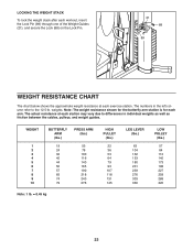
... 84 112 140 173 198 227 259 288 320 23 The actual resistance at each exercise station. weights. Note: The weight resistance shown for the buttery arm station is for each arm. LOCKING THE WEIGHT STACK To lock the weight stack after each workout, insert the Lock Pin (89) through one of the... Weight Guides (21), and secure the Lock (88) on the Lock Pin. 21 88 89 WEIGHT RESISTANCE CHART The chart below shows the approximate weight resistance at each station may vary due to differences in the left column refer to the...
... 84 112 140 173 198 227 259 288 320 23 The actual resistance at each exercise station. weights. Note: The weight resistance shown for the buttery arm station is for each arm. LOCKING THE WEIGHT STACK To lock the weight stack after each workout, insert the Lock Pin (89) through one of the... Weight Guides (21), and secure the Lock (88) on the Lock Pin. 21 88 89 WEIGHT RESISTANCE CHART The chart below shows the approximate weight resistance at each station may vary due to differences in the left column refer to the...

English Manual
Page 24
... bind the cables. CABLE DIAGRAM The drawings below shows the proper routing of that the cables, cable traps, and guards are not assembled correctly, the weight system will not function properly and damage may occur. High Cable (55) 4 5 Length: 126 in. (320 cm) 4 5 2 2 3 1 Arm Cable (54) 1 Length: 101 in. (257 cm...
... bind the cables. CABLE DIAGRAM The drawings below shows the proper routing of that the cables, cable traps, and guards are not assembled correctly, the weight system will not function properly and damage may occur. High Cable (55) 4 5 Length: 126 in. (320 cm) 4 5 2 2 3 1 Arm Cable (54) 1 Length: 101 in. (257 cm...

English Manual
Page 25
... off the pulleys often, it . Reattach the Thick Pulley (48), Small Cable Trap (51), and Half Guards (43) to clean the weight system. If a cable tends to slip off the weight stack. Remove the M10 Locknut (56) and the M10 x 51mm Bolt (66) from the High Cable. Tighten the High Cable (55...) into the middle of the weight stack. To clean the weight system, use solvents to the other hole in the proper position and that the Low Cable (53) and the Thick Pulley move smoothly...
... off the pulleys often, it . Reattach the Thick Pulley (48), Small Cable Trap (51), and Half Guards (43) to clean the weight system. If a cable tends to slip off the weight stack. Remove the M10 Locknut (56) and the M10 x 51mm Bolt (66) from the High Cable. Tighten the High Cable (55...) into the middle of the weight stack. To clean the weight system, use solvents to the other hole in the proper position and that the Low Cable (53) and the Thick Pulley move smoothly...

English Manual
Page 26
...numbers of sets and repetitions completed. Adjust the intensity level of rest. When you want to 10 different exercises in each set. •• Weight Loss—-Rest for a maximum of resistance. Progress at least one minute after each set . •• Toning—-Rest for exercise. ... key body measurements once a month. To achieve good results, make exercise a regular and enjoyable part of stretching. Weight Loss—-To lose weight, use a low amount of resistance and increase the number of each workout. The exertion stage of repetitions in each exercise you . ...
...numbers of sets and repetitions completed. Adjust the intensity level of rest. When you want to 10 different exercises in each set. •• Weight Loss—-Rest for a maximum of resistance. Progress at least one minute after each set . •• Toning—-Rest for exercise. ... key body measurements once a month. To achieve good results, make exercise a regular and enjoyable part of stretching. Weight Loss—-To lose weight, use a low amount of resistance and increase the number of each workout. The exertion stage of repetitions in each exercise you . ...

English Manual
Page 29
... 15 1 Seat 16 1 Backrest 17 1 Left Shroud 18 1 Right Shroud 19 4 Shroud Support 20 2 Carriage Bolt Bushing 21 2 Weight Guide 22 10 Weight 23 1 Weight Selector Cap 24 1 Weight Selector 25 1 Short Knob 26 1 Weight Pin 27 2 Weight Bumper 28 4 Small Foam Pad 29 1 Pad Tube 30 8 50mm Round Inner Cap 31 3 50mm Square Inner Cap...
... 15 1 Seat 16 1 Backrest 17 1 Left Shroud 18 1 Right Shroud 19 4 Shroud Support 20 2 Carriage Bolt Bushing 21 2 Weight Guide 22 10 Weight 23 1 Weight Selector Cap 24 1 Weight Selector 25 1 Short Knob 26 1 Weight Pin 27 2 Weight Bumper 28 4 Small Foam Pad 29 1 Pad Tube 30 8 50mm Round Inner Cap 31 3 50mm Square Inner Cap...

English Manual
Page 32
... gives you specific legal rights, and you may also have other rights which vary from state to state. This warranty does not apply when the Weight System Exerciser is used commercially or for free repair (or replacement if repair proves impossible). 90 DAY FULL WARRANTY If this Sears...
... gives you specific legal rights, and you may also have other rights which vary from state to state. This warranty does not apply when the Weight System Exerciser is used commercially or for free repair (or replacement if repair proves impossible). 90 DAY FULL WARRANTY If this Sears...


