
English Manual
Page 1
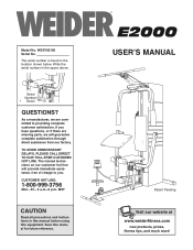
... to providing complete customer satisfaction. Model No. Write the serial number in the location shown below. If you have questions, or if there are missing parts, we are committed to you.
... to providing complete customer satisfaction. Model No. Write the serial number in the location shown below. If you have questions, or if there are missing parts, we are committed to you.

English Manual
Page 2
Table of Contents Important Precautions 3 Before You Begin 4 Assembly 5 Cable Diagram 19 How to Use the Weight System 20 Trouble-shooting and Maintenance 21 Ordering Replacement Parts Back Cover Limited Warranty Back Cover Note: A PART LIST/EXPLODED DRAWING and a PART IDENTIFICATION CHART are attached to the center of this manual. Remove the PART LIST/EXPLODED DRAWING and the PART IDENTIFICATION CHART before beginning assembly. 2
Table of Contents Important Precautions 3 Before You Begin 4 Assembly 5 Cable Diagram 19 How to Use the Weight System 20 Trouble-shooting and Maintenance 21 Ordering Replacement Parts Back Cover Limited Warranty Back Cover Note: A PART LIST/EXPLODED DRAWING and a PART IDENTIFICATION CHART are attached to the center of this manual. Remove the PART LIST/EXPLODED DRAWING and the PART IDENTIFICATION CHART before beginning assembly. 2
English Manual
Page 3
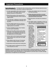
... all instructions before using. Replace any exercise program, consult your physician. If you are adequately informed of 12 and pets away from moving parts. 10. Keep children under the age of all instructions in this product. 3 Keep hands and feet away from the weight system at ...been placed on a level surface. Important Precautions WARNING: To reduce the risk of 35 or persons with pre-existing health problems. Read all parts often. Cover the floor or carpet beneath the weight system for foot protection when exercising. 12. Keep the power cord away from the ...
... all instructions before using. Replace any exercise program, consult your physician. If you are adequately informed of 12 and pets away from moving parts. 10. Keep children under the age of all instructions in this product. 3 Keep hands and feet away from the weight system at ...been placed on a level surface. Important Precautions WARNING: To reduce the risk of 35 or persons with pre-existing health problems. Read all parts often. Cover the floor or carpet beneath the weight system for foot protection when exercising. 12. Keep the power cord away from the ...
English Manual
Page 4
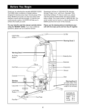
... muscle size and strength, or improve your cardiovascular system, the E2000 will help us assist you, please note the product model number and serial number before using the WEIDER¨ E2000. Length: 61 in . The E2000 offers a selection of this manual carefully before calling. Whether your... benefit, read this manual). If you to the E2000 (see the front cover of weight stations designed to familiarize yourself with the major parts and how they...
... muscle size and strength, or improve your cardiovascular system, the E2000 will help us assist you, please note the product model number and serial number before using the WEIDER¨ E2000. Length: 61 in . The E2000 offers a selection of this manual carefully before calling. Whether your... benefit, read this manual). If you to the E2000 (see the front cover of weight stations designed to familiarize yourself with the major parts and how they...
English Manual
Page 5
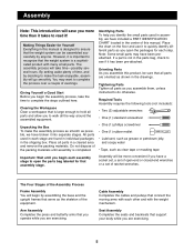
... you begin each stage are oriented as you assemble them, unless instructed to ensure that connect the moving arms with each step. If a part is completed. The Four Stages of the Assembly Process Frame Assembly You will begin the assembly process, take timeÑpossibly several hours. All... parts used in assembly, we have broken it into separate stages. Place all parts as shown in a cleared area and remove the packing materials. Place the chart on the floor and use...
... you begin each stage are oriented as you assemble them, unless instructed to ensure that connect the moving arms with each step. If a part is completed. The Four Stages of the Assembly Process Frame Assembly You will begin the assembly process, take timeÑpossibly several hours. All... parts used in assembly, we have broken it into separate stages. Place all parts as shown in a cleared area and remove the packing materials. Place the chart on the floor and use...
English Manual
Page 6
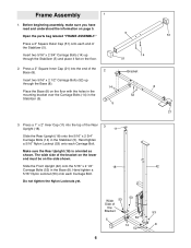
Open the parts bag labeled ÒFRAME ASSEMBLY.Ó Press a 2Ó Square Outer Cap (51) onto each Carriage Bolt. Press a 1Ó x 2Ó Inner Cap (11) into the end ...
Open the parts bag labeled ÒFRAME ASSEMBLY.Ó Press a 2Ó Square Outer Cap (51) onto each Carriage Bolt. Press a 1Ó x 2Ó Inner Cap (11) into the end ...
English Manual
Page 8
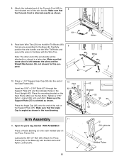
... the Base (8). Make sure that the Angle Cap is left between the wires and the Weight Mechanism (26, not shown) for this purpose. Open the parts bag labeled ÒARM ASSEMBLY.Ó Press a Plastic Bushing (7) onto each Bolt. Insert two 5/16Ó x 2 3/4Ó Bolts (67) through the Support Plate (27) and...
... the Base (8). Make sure that the Angle Cap is left between the wires and the Weight Mechanism (26, not shown) for this purpose. Open the parts bag labeled ÒARM ASSEMBLY.Ó Press a Plastic Bushing (7) onto each Bolt. Insert two 5/16Ó x 2 3/4Ó Bolts (67) through the Support Plate (27) and...
English Manual
Page 9
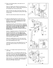
... a 3/8Ó Nylon Locknut (57). 36 91 44 33 22 Lubricate 29 57 55 9 Lubricate a 5/16Ó x 2 1/2Ó Bolt (22). Note: In the following steps, some parts are not shown for this step. Note the position of each Arm. Press a 1 1/2Ó Square Inner Cap (33) into the indicated hole in the Press...
... a 3/8Ó Nylon Locknut (57). 36 91 44 33 22 Lubricate 29 57 55 9 Lubricate a 5/16Ó x 2 1/2Ó Bolt (22). Note: In the following steps, some parts are not shown for this step. Note the position of each Arm. Press a 1 1/2Ó Square Inner Cap (33) into the indicated hole in the Press...
English Manual
Page 10
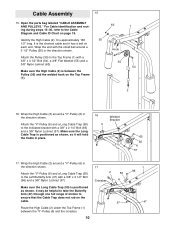
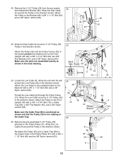
... the ÒVÓ-Pulley (6) and a Long Cable Trap (50) to the indicated bracket with a 3/8Ó x 2 1/2Ó Bolt (96) and a 3/8Ó Nylon Locknut (57). Open the parts bag labeled ÒCABLE ASSEMBLY AND PULLEYS.Ó For Cable identification and routing during steps 15Ð30, refer to the Top Frame (1) with the...
... the ÒVÓ-Pulley (6) and a Long Cable Trap (50) to the indicated bracket with a 3/8Ó x 2 1/2Ó Bolt (96) and a 3/8Ó Nylon Locknut (57). Open the parts bag labeled ÒCABLE ASSEMBLY AND PULLEYS.Ó For Cable identification and routing during steps 15Ð30, refer to the Top Frame (1) with the...
English Manual
Page 12
... 3 1/2Ó Pulley (35) attached to the lowest holes in the inset drawing. 23 Small Tabs 63 55 32 35 2 32 42 24. Make sure the parts are assembled exactly as shown and that the Pulley (35) is positioned as shown in the Pulley Plates (31) with a 3/8Ó x 4 1/2Ó Bolt (93), two...
... 3 1/2Ó Pulley (35) attached to the lowest holes in the inset drawing. 23 Small Tabs 63 55 32 35 2 32 42 24. Make sure the parts are assembled exactly as shown and that the Pulley (35) is positioned as shown in the Pulley Plates (31) with a 3/8Ó x 4 1/2Ó Bolt (93), two...
English Manual
Page 14
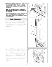
.... Tighten a 1/4Ó Nylon Locknut (89) with two 1/4Ó x 2 1/2Ó Screws (43) and two 1/4Ó Flat 42 Washers (90). 43 90 41 43 32. Open the parts bag labeled ÒSEAT ASSEMBLY.Ó Attach the Backrest (41) to the Seat Frame (36) with a Cable Clip (73). Insert the 1/4Ó x 2Ó Carriage Bolt... the Low Cable (9) around a 3 1/2Ó Pulley (35) in the Seat Plate (37). Insert the 1/4Ó x 2Ó Carriage Bolt (38) into the indicated hole in the parts bag labeled ÒSEAT ASSEMBLY.Ó 12 Seat Assembly 31 9 73 44 31. 30.
.... Tighten a 1/4Ó Nylon Locknut (89) with two 1/4Ó x 2 1/2Ó Screws (43) and two 1/4Ó Flat 42 Washers (90). 43 90 41 43 32. Open the parts bag labeled ÒSEAT ASSEMBLY.Ó Attach the Backrest (41) to the Seat Frame (36) with a Cable Clip (73). Insert the 1/4Ó x 2Ó Carriage Bolt... the Low Cable (9) around a 3 1/2Ó Pulley (35) in the Seat Plate (37). Insert the 1/4Ó x 2Ó Carriage Bolt (38) into the indicated hole in the parts bag labeled ÒSEAT ASSEMBLY.Ó 12 Seat Assembly 31 9 73 44 31. 30.
English Manual
Page 16
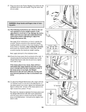
..., stop running the console and loosen the locknut shown in the inset drawing. If the brass piece is too loose, there will have difficulty moving parts. 38a.The following instructions are critical to the indicated screw. 38b.Check the brass piece that no movement can damage the motor. rect operation of...
..., stop running the console and loosen the locknut shown in the inset drawing. If the brass piece is too loose, there will have difficulty moving parts. 38a.The following instructions are critical to the indicated screw. 38b.Check the brass piece that no movement can damage the motor. rect operation of...
English Manual
Page 18
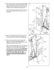
... bottom screws on the Shroud. The use of this manual. If there is used. See TROUBLE-SHOOTING AND MAINTENANCE on page 20 of the remaining parts will need to remove the slack by tightening the cables. Make sure that the cables move smoothly, find and correct the problem. IMPORTANT: If the... cables are not properly installed, they may be sure that all parts have been properly tightened. Attach the power cord jack to be damaged when heavy weight is any slack in the Top 40 Frame (1), the Base...
... bottom screws on the Shroud. The use of this manual. If there is used. See TROUBLE-SHOOTING AND MAINTENANCE on page 20 of the remaining parts will need to remove the slack by tightening the cables. Make sure that the cables move smoothly, find and correct the problem. IMPORTANT: If the... cables are not properly installed, they may be sure that all parts have been properly tightened. Attach the power cord jack to be damaged when heavy weight is any slack in the Top 40 Frame (1), the Base...
English Manual
Page 20
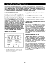
... any tension on pages 16 and 17 if the motor binds or hesitates while resetting the console. If at minimum or maximum weight for each part of the bar with one hand while adjusting the weight. Power ButtonÑTurns the power on the arm press and butterfly stations. To increase...
... any tension on pages 16 and 17 if the motor binds or hesitates while resetting the console. If at minimum or maximum weight for each part of the bar with one hand while adjusting the weight. Power ButtonÑTurns the power on the arm press and butterfly stations. To increase...
English Manual
Page 22
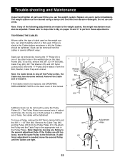
...), Cable Trap (66), 3/8Ó Flat Washer (55) and 3/8Ó Nylon Locknut (63). By moving one or both pulleys to be replaced, see ORDERING REPLACEMENT PARTS on pages 16 and 17 to the weight system, the weight mechanism must also be removed by using a damp cloth and mild non-abrasive detergent... Cables are still too loose, move the same Pulley to one Pulley to the second adjustment hole. Trouble-shooting and Maintenance Inspect and tighten all parts each time you use solvents. Slack can be tightened. Remove the Cable Trap (66) and the Pulley (35) from the cables in the ...
...), Cable Trap (66), 3/8Ó Flat Washer (55) and 3/8Ó Nylon Locknut (63). By moving one or both pulleys to be replaced, see ORDERING REPLACEMENT PARTS on pages 16 and 17 to the weight system, the weight mechanism must also be removed by using a damp cloth and mild non-abrasive detergent... Cables are still too loose, move the same Pulley to one Pulley to the second adjustment hole. Trouble-shooting and Maintenance Inspect and tighten all parts each time you use solvents. Slack can be tightened. Remove the Cable Trap (66) and the Pulley (35) from the cables in the ...

English Manual
Page 24
Part Identification ChartÑWESY92190 R1299A 5/16" Nylon Locknut (53) 5/16" Nylon Jamnut (91) 3/8" Plain Nut (85) 3/8" Nylon Jamnut (63) 3/8" Nylon Locknut (57) 1/4" x 3/4" Screw (17) 5/16" x 1 3/4" Bolt (58) 1/4" x 2" Carriage Bolt (38) 1/4" x 2" Bolt (71) 1/4" x 2 1/2" Screw (43) 1/2" Nylon Locknut (68) 5/16" x 2 1/2" Bolt (22) 5/16" Flat Washer (56) 5/16" x 2 1/2" Carriage Bolt (52) 3/8" Flat Washer (55) 5/16" x 2 3/4" Bolt (67) 5/16" x 2 3/4" Carriage Bolt (14)
Part Identification ChartÑWESY92190 R1299A 5/16" Nylon Locknut (53) 5/16" Nylon Jamnut (91) 3/8" Plain Nut (85) 3/8" Nylon Jamnut (63) 3/8" Nylon Locknut (57) 1/4" x 3/4" Screw (17) 5/16" x 1 3/4" Bolt (58) 1/4" x 2" Carriage Bolt (38) 1/4" x 2" Bolt (71) 1/4" x 2 1/2" Screw (43) 1/2" Nylon Locknut (68) 5/16" x 2 1/2" Bolt (22) 5/16" Flat Washer (56) 5/16" x 2 1/2" Carriage Bolt (52) 3/8" Flat Washer (55) 5/16" x 2 3/4" Bolt (67) 5/16" x 2 3/4" Carriage Bolt (14)
English Manual
Page 26
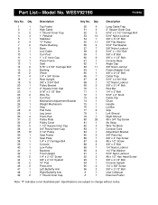
...; Hex Head Screw 3/8Ó x 4 1/2Ó Bolt Console Upright 1/4Ó x 5/8Ó Screw 3/8Ó x 2 1/2Ó Bolt UserÕs Manual Exercise Poster Note: Ò#Ó indicates a non-illustrated part. Part ListÑModel No. Specifications are subject to change without notice.
...; Hex Head Screw 3/8Ó x 4 1/2Ó Bolt Console Upright 1/4Ó x 5/8Ó Screw 3/8Ó x 2 1/2Ó Bolt UserÕs Manual Exercise Poster Note: Ò#Ó indicates a non-illustrated part. Part ListÑModel No. Specifications are subject to change without notice.
English Manual
Page 28
... other consequential damages of the product (WESY92190) 2. The SERIAL NUMBER of the product (see the PART LIST and EXPLODED DRAWING attached at one of the product (WEIDER¨ E2000) 3. No other warranty beyond that specifically set forth herein. Part No. 160370 R1299A Printed in connection with the use or performance of the product or...
... other consequential damages of the product (WESY92190) 2. The SERIAL NUMBER of the product (see the PART LIST and EXPLODED DRAWING attached at one of the product (WEIDER¨ E2000) 3. No other warranty beyond that specifically set forth herein. Part No. 160370 R1299A Printed in connection with the use or performance of the product or...


