

English Manual
Page 1
Write the serial number in the space above for future reference. The trained technicians on our customer hot line will guarantee you complete satisfaction through direct assistance from our factory. MST CAUTION Read all precautions and instructions in the center of charge to providing complete customer satisfaction. Save this equipment. WESY49202 Serial No. TABLE OF CONTENTS IMPORTANT PRECAUTIONS 2 BEFORE YOU BEGIN 3 ASSEMBLY 4 ADJUSTMENTS 22 WEIGHT RESISTANCE CHART 24 TROUBLESHOOTING AND MAINTENANCE 25 CABLE DIAGRAMS 26 ORDERING REPLACEMENT PARTS Back Cover LIMITED ...
Write the serial number in the space above for future reference. The trained technicians on our customer hot line will guarantee you complete satisfaction through direct assistance from our factory. MST CAUTION Read all precautions and instructions in the center of charge to providing complete customer satisfaction. Save this equipment. WESY49202 Serial No. TABLE OF CONTENTS IMPORTANT PRECAUTIONS 2 BEFORE YOU BEGIN 3 ASSEMBLY 4 ADJUSTMENTS 22 WEIGHT RESISTANCE CHART 24 TROUBLESHOOTING AND MAINTENANCE 25 CABLE DIAGRAMS 26 ORDERING REPLACEMENT PARTS Back Cover LIMITED ...

English Manual
Page 2
... system at 1-800-999-3756 and order a free replacement decal. Your hand could become pinched between the leg press upright and the military press arm. 16. Always disconnect the lat bar from moving parts. 8. The weight system is missing or illegible, call our toll-free Customer Hot Line at all instructions...
... system at 1-800-999-3756 and order a free replacement decal. Your hand could become pinched between the leg press upright and the military press arm. 16. Always disconnect the lat bar from moving parts. 8. The weight system is missing or illegible, call our toll-free Customer Hot Line at all instructions...

English Manual
Page 3
Mountain Time (excluding holidays). If you for selecting the versatile CLUB WEIDER® 16.6ST weight system. Length: 92 in . The 16.6ST weight system offers a selection of weight stations designed to develop every major muscle group of this manual carefully before calling. Width: 110 in . BEFORE...: Height: 78 in. The model number is to tone your body, build dramatic muscle size and strength, or improve your cardiovascular system, the 16.6ST weight system will help us assist you want. To help you to the weight system (see the front cover of the body. The serial number...
Mountain Time (excluding holidays). If you for selecting the versatile CLUB WEIDER® 16.6ST weight system. Length: 92 in . The 16.6ST weight system offers a selection of weight stations designed to develop every major muscle group of this manual carefully before calling. Width: 110 in . BEFORE...: Height: 78 in. The model number is to tone your body, build dramatic muscle size and strength, or improve your cardiovascular system, the 16.6ST weight system will help us assist you want. To help you to the weight system (see the front cover of the body. The serial number...

English Manual
Page 4
FRAME ASSEMBLY 1. Press two 50mm Square Outer Caps (51) onto the Stabilizer (5). Attach the Base (4) to see if it has been pre-attached. • As you assemble the weight system be needed. Before beginning assembly, be more convenient if you have read the following tools: A socket set, a set of open-end or closed-end wrenches, or a set of this manual. Insert six M8 x 65mm Carriage Bolts (1) up through the Stabilizer (5). Do not tighten the Nylon Locknuts yet. 1 51 11 8 8 5 1 51 1 3 4 1 27 4 ASSEMBLY Before beginning assembly, carefully read and understand the ...
FRAME ASSEMBLY 1. Press two 50mm Square Outer Caps (51) onto the Stabilizer (5). Attach the Base (4) to see if it has been pre-attached. • As you assemble the weight system be needed. Before beginning assembly, be more convenient if you have read the following tools: A socket set, a set of open-end or closed-end wrenches, or a set of this manual. Insert six M8 x 65mm Carriage Bolts (1) up through the Stabilizer (5). Do not tighten the Nylon Locknuts yet. 1 51 11 8 8 5 1 51 1 3 4 1 27 4 ASSEMBLY Before beginning assembly, carefully read and understand the ...

English Manual
Page 5
Do not tighten the Nylon Locknuts yet. The high side of Brackets 56 3 5 1 FRAME ASSEMBLY 4 1 42 6 3 5 Attach the Rubber Bumper (91) to the Leg Press Upright (56) with the M4 x 16mm Selftapping Screw (87). 2 27 74 87 91 27 3 3 3 1 3. Hand tighten four M8 Nylon Locknuts (3) onto the Carriage Bolts. Press a 25mm Square Inner Cap (6) into the Assist Upright (74). Do not tighten the Nylon Locknuts yet. 2. Press a 50mm Square Inner Cap into the Front Upright (42). 27 High Sides of the brackets on the Assist Upright and Leg Press Upright should be on the side shown. ...
Do not tighten the Nylon Locknuts yet. The high side of Brackets 56 3 5 1 FRAME ASSEMBLY 4 1 42 6 3 5 Attach the Rubber Bumper (91) to the Leg Press Upright (56) with the M4 x 16mm Selftapping Screw (87). 2 27 74 87 91 27 3 3 3 1 3. Hand tighten four M8 Nylon Locknuts (3) onto the Carriage Bolts. Press a 25mm Square Inner Cap (6) into the Assist Upright (74). Do not tighten the Nylon Locknuts yet. 2. Press a 50mm Square Inner Cap into the Front Upright (42). 27 High Sides of the brackets on the Assist Upright and Leg Press Upright should be on the side shown. ...
English Manual
Page 6
Press a 45mm Square Inner Cap (44) into each stack of the Rear Seat Frame (100) to the Front 11 Upright (42) with two M8 x 70mm Bolts (11), two M8 Washers (8), and two M8 Nylon Locknuts (3). Do not tighten the M8 Nylon Locknuts (3) yet. 55 11 113 8 44 3 44 Crossbar 3 56 42 74 FRAME ASSEMBLY 5. Hand tighten two M8 Nylon Locknuts (3) onto the Carriage Bolts. Set two Weight Bumpers (19) on the bracket on the Top Frame. 4. Press two 25mm Inner Caps (113) into the 4 end of the crossbar on the Stabilizer (5). Slide the Rear Seat Frame (100) onto the indicated M8 x ...
Press a 45mm Square Inner Cap (44) into each stack of the Rear Seat Frame (100) to the Front 11 Upright (42) with two M8 x 70mm Bolts (11), two M8 Washers (8), and two M8 Nylon Locknuts (3). Do not tighten the M8 Nylon Locknuts (3) yet. 55 11 113 8 44 3 44 Crossbar 3 56 42 74 FRAME ASSEMBLY 5. Hand tighten two M8 Nylon Locknuts (3) onto the Carriage Bolts. Set two Weight Bumpers (19) on the bracket on the Top Frame. 4. Press two 25mm Inner Caps (113) into the 4 end of the crossbar on the Stabilizer (5). Slide the Rear Seat Frame (100) onto the indicated M8 x ...

English Manual
Page 7
Lubricate the inside of Weights. Set the Top Weight onto the rear stack of Weights (25). Set the Top Weight onto the front stack of Weights (25). Be sure that the pin on the Weight Tube is sitting in the pin groove in the other Top Weight (65). Be sure that the pin on the Weight Tube is sitting in the pin groove in the Weight Guides are at the top, as shown. 25 8 Holes 73 Lubricate 65 Pin 63 64 Pin Groove 25 7 Press a Weight Tube Bumper (64) into the stack of the holes in the top Weight. Insert both Long Weight Guides (62) into the rear stack of the ...
Lubricate the inside of Weights. Set the Top Weight onto the rear stack of Weights (25). Set the Top Weight onto the front stack of Weights (25). Be sure that the pin on the Weight Tube is sitting in the pin groove in the other Top Weight (65). Be sure that the pin on the Weight Tube is sitting in the pin groove in the Weight Guides are at the top, as shown. 25 8 Holes 73 Lubricate 65 Pin 63 64 Pin Groove 25 7 Press a Weight Tube Bumper (64) into the stack of the holes in the top Weight. Insert both Long Weight Guides (62) into the rear stack of the ...

English Manual
Page 8
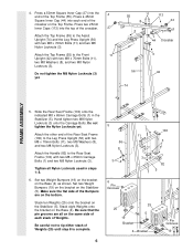
Locate and open the parts bag labeled "ARM ASSEMBLY." Make sure there is a Bushing (98) in each 11 welded spacer on the side shown. the Leg Press Arm must be on the Leg Press Plate (95) with the Bolt and an M10 Nylon Locknut (21). Attach the Press Frame (17) to pivot freely. Do not overtighten the Nylon Locknut; Attach the Leg Press Plate to the Top Frame (55) with an M8 x 150mm Bolt (60), two 19.5mm Spacers (61), and an M8 Nylon Locknut (3). the Plastic Bushings should fit snugly over the ends of the Stabilizer (5). Do not overtighten the Locknut; Attach the upper ...
Locate and open the parts bag labeled "ARM ASSEMBLY." Make sure there is a Bushing (98) in each 11 welded spacer on the side shown. the Leg Press Arm must be on the Leg Press Plate (95) with the Bolt and an M10 Nylon Locknut (21). Attach the Press Frame (17) to pivot freely. Do not overtighten the Nylon Locknut; Attach the Leg Press Plate to the Top Frame (55) with an M8 x 150mm Bolt (60), two 19.5mm Spacers (61), and an M8 Nylon Locknut (3). the Plastic Bushings should fit snugly over the ends of the Stabilizer (5). Do not overtighten the Locknut; Attach the upper ...

English Manual
Page 9
Identify the Right Arm (48) and the Left Arm (47). Attach a "V"-Pulley (50) and a Long Cable Trap (31) to one of the Press Arms (46). Slide the Right Arm (48) onto the right axle. Do not tighten the Locknut yet. Be sure that the teeth on the Top Frame (55). Press 45mm Square Inner Caps (44) into the Press Arm. Slide a Large Foam Pad (45) onto the lower end of the Right and Left Arms (47, 48). Press a 45mm Square Inner Cap (44) into the lower ends of each Arm. Assemble the Left Arm (47) in the same manner. 13. Assemble the other Press Arm (46) in the same manner. ...
Identify the Right Arm (48) and the Left Arm (47). Attach a "V"-Pulley (50) and a Long Cable Trap (31) to one of the Press Arms (46). Slide the Right Arm (48) onto the right axle. Do not tighten the Locknut yet. Be sure that the teeth on the Top Frame (55). Press 45mm Square Inner Caps (44) into the Press Arm. Slide a Large Foam Pad (45) onto the lower end of the Right and Left Arms (47, 48). Press a 45mm Square Inner Cap (44) into the lower ends of each Arm. Assemble the Left Arm (47) in the same manner. 13. Assemble the other Press Arm (46) in the same manner. ...

English Manual
Page 10
... the Assist Arm (105) to pivot easily. 32 49 49 32 84 101 67 56 33 101 16. The Assist Arm must 74 be able to the lowest hole in the Leg Press Upright (56). Press two 38mm Square Inner Caps (32) into ...
... the Assist Arm (105) to pivot easily. 32 49 49 32 84 101 67 56 33 101 16. The Assist Arm must 74 be able to the lowest hole in the Leg Press Upright (56). Press two 38mm Square Inner Caps (32) into ...
English Manual
Page 11
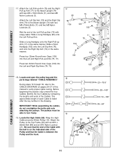
Slide a Short Handgrip (102) onto the Left Dip Arm (78), and onto the Right Dip Arm (79) in the same manner. Before beginning this manual to the CABLE DIAGRAMS on pages 26-27 of the Pulley and that the Cable is listed after the key number in the drawing. Attach the Left Dip Arm (78) and the Right Dip Arm (79) to turn freely. 19 19. Locate and open the pulley bag and the parts bags labeled "CABLE ASSEMBLY." 18 During steps 19 through 39, refer to verify proper cable routing. Be sure that the end of the Cable with the ball is on the indicated side of this section, fully ...
Slide a Short Handgrip (102) onto the Left Dip Arm (78), and onto the Right Dip Arm (79) in the same manner. Before beginning this manual to the CABLE DIAGRAMS on pages 26-27 of the Pulley and that the Cable is listed after the key number in the drawing. Attach the Left Dip Arm (78) and the Right Dip Arm (79) to turn freely. 19 19. Locate and open the pulley bag and the parts bags labeled "CABLE ASSEMBLY." 18 During steps 19 through 39, refer to verify proper cable routing. Be sure that the end of the Cable with the ball is on the indicated side of this section, fully ...

English Manual
Page 12
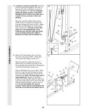
Be sure that the Cable 3 15 58 Trap (66) is positioned to the Top 23 Frame (55) with an M10 x 55mm Bolt (86) and an M10 Nylon Locknut (21). the Pulley Bracket must be able to the Pulley Bracket (20). Attach the Pulley and a Long Cable Trap (31) to hold the Cable in the groove of the Pulley and that the Long Cable Trap is turned to the indicated bracket on the Front Upright (42) with the M8 x 120mm Bolt (68) 68 and an M8 Nylon Locknut (3). Tighten the M10 x 55mm Bolt (86) and the M10 Nylon Locknut (not shown). 31 86 50 58 48 CABLE ASSEMBLY 23. Be ...
Be sure that the Cable 3 15 58 Trap (66) is positioned to the Top 23 Frame (55) with an M10 x 55mm Bolt (86) and an M10 Nylon Locknut (21). the Pulley Bracket must be able to the Pulley Bracket (20). Attach the Pulley and a Long Cable Trap (31) to hold the Cable in the groove of the Pulley and that the Long Cable Trap is turned to the indicated bracket on the Front Upright (42) with the M8 x 120mm Bolt (68) 68 and an M8 Nylon Locknut (3). Tighten the M10 x 55mm Bolt (86) and the M10 Nylon Locknut (not shown). 31 86 50 58 48 CABLE ASSEMBLY 23. Be ...

English Manual
Page 13
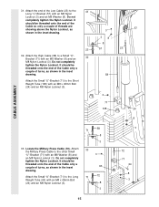
Be sure that the Cable and Pulley move smoothly. 25 55 58 15 12 57 58 Bracket 15 58 12 15 21 26. Attach the Pulley to the bracket on the Top Frame (55) with an M10 x 50mm Bolt (12) and an M10 Nylon Locknut (21). the Bolt has been shown removed for shipping purposes. Remove the M10 Nylon Locknut (21), the Spacer, and the 90mm Pulley (15) from the M10 x 95mm Bolt (88). Slide the 15mm Spacer (7) back onto the M10 x 95mm Bolt (88). 9 88 7 17 15 21 13 Note: This may come preassembled. Wrap the High Cable (58) around the 90mm Pulley (15) shown in the inset drawing....
Be sure that the Cable and Pulley move smoothly. 25 55 58 15 12 57 58 Bracket 15 58 12 15 21 26. Attach the Pulley to the bracket on the Top Frame (55) with an M10 x 50mm Bolt (12) and an M10 Nylon Locknut (21). the Bolt has been shown removed for shipping purposes. Remove the M10 Nylon Locknut (21), the Spacer, and the 90mm Pulley (15) from the M10 x 95mm Bolt (88). Slide the 15mm Spacer (7) back onto the M10 x 95mm Bolt (88). 9 88 7 17 15 21 13 Note: This may come preassembled. Wrap the High Cable (58) around the 90mm Pulley (15) shown in the inset drawing....
English Manual
Page 14
Attach the Pulley to the upper hole in the 29 Press Frame (17). Be sure that the Cable Trap (66) is turned to hold the Cable in the Front Upright (42). Remove the indicated 90mm Pulley (15) from the lower hole in place and that the Cable is routed around the Pulley and reattach the Pulley and Cable Trap (66) to the Front Upright (42) with an M10 Nylon Locknut (21). See the 42 15 inset drawing. Route the Low Cable (23) around the Pulley and reattach the Pulley to the upper hole in the Press Frame (17) with an M10 x 95mm Bolt (88) and an M10 Nylon Locknut (21). ...
Attach the Pulley to the upper hole in the 29 Press Frame (17). Be sure that the Cable Trap (66) is turned to hold the Cable in the Front Upright (42). Remove the indicated 90mm Pulley (15) from the lower hole in place and that the Cable is routed around the Pulley and reattach the Pulley and Cable Trap (66) to the Front Upright (42) with an M10 Nylon Locknut (21). See the 42 15 inset drawing. Route the Low Cable (23) around the Pulley and reattach the Pulley to the upper hole in the Press Frame (17) with an M10 x 95mm Bolt (88) and an M10 Nylon Locknut (21). ...
English Manual
Page 15
Attach the High Cable (58) to a Small "U"Bracket (71) with an M8 x 45mm Bolt (24) and an M8 Nylon Locknut (3). 3 38 8 57 58 3 71 108 58 71 8 3 33. Do not completely tighten the Nylon Locknut. Attach the Small "U"-Bracket (71) to the other Small "U"-Bracket (71) with an M8 Nylon Locknut (3) and an M8 Washer (8). Locate the Military Press Cable (72). Attach 33 the Military Press Cable to the Short Weight Tube (108) with an M8 Washer (8) and an 32 M8 Nylon Locknut (3). Attach the end of turns, as shown in the inset drawing. 23 32. Attach the Small "U"-...
Attach the High Cable (58) to a Small "U"Bracket (71) with an M8 x 45mm Bolt (24) and an M8 Nylon Locknut (3). 3 38 8 57 58 3 71 108 58 71 8 3 33. Do not completely tighten the Nylon Locknut. Attach the Small "U"-Bracket (71) to the other Small "U"-Bracket (71) with an M8 Nylon Locknut (3) and an M8 Washer (8). Locate the Military Press Cable (72). Attach 33 the Military Press Cable to the Short Weight Tube (108) with an M8 Washer (8) and an 32 M8 Nylon Locknut (3). Attach the end of turns, as shown in the inset drawing. 23 32. Attach the Small "U"-...

English Manual
Page 16
... around a 34 "V"-Pulley (50). Be sure that the Cable and Pulley move smoothly. 105 35 74 50 9 112 105 Bracket 31 21 72 76 15 16 Wrap the Military Press Cable (72) around a 90mm Pulley (15). Wrap the Military Press Cable (72) around the Pulley as shown. Be sure that the...
... around a 34 "V"-Pulley (50). Be sure that the Cable and Pulley move smoothly. 105 35 74 50 9 112 105 Bracket 31 21 72 76 15 16 Wrap the Military Press Cable (72) around a 90mm Pulley (15). Wrap the Military Press Cable (72) around the Pulley as shown. Be sure that the...

English Manual
Page 17
Fully tighten an M8 Nylon Locknut (3) onto the Bolt. Be sure that the Pulley is on the side shown and that the Cable Trap is positioned to pivot. 37 15 57 72 21 57 3 72 93 15 A 66 12 B 17 Thread another M8 Nylon Locknut (3) onto the Bolt. There must be room between the two Locknuts for the end of the Cable to hold the Cable in the Pivot Arm (101). The Bolt must be inserted from the side shown. Attach a 90mm Pulley (15) and a Cable Trap (66) to the Pivot Arm (101) with an M10 x 50mm Bolt (12) and an M10 Nylon Locknut (21). Be sure that the Cable and Pulley move...
Fully tighten an M8 Nylon Locknut (3) onto the Bolt. Be sure that the Pulley is on the side shown and that the Cable Trap is positioned to pivot. 37 15 57 72 21 57 3 72 93 15 A 66 12 B 17 Thread another M8 Nylon Locknut (3) onto the Bolt. There must be room between the two Locknuts for the end of the Cable to hold the Cable in the Pivot Arm (101). The Bolt must be inserted from the side shown. Attach a 90mm Pulley (15) and a Cable Trap (66) to the Pivot Arm (101) with an M10 x 50mm Bolt (12) and an M10 Nylon Locknut (21). Be sure that the Cable and Pulley move...
English Manual
Page 18
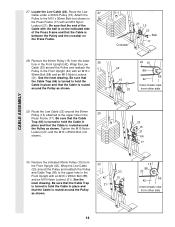
Wrap the Leg Press Cable (99) around a 90mm Pulley (15). Note: The three holes are for the end of the Cable to pivot. Be sure that the Cable and Pulley move smoothly and that the Cable is between the two bolts for cable adjustment. Tighten an M8 Nylon Locknut (3) onto the Bolt. Do not fully tighten the second Locknut. Attach the Pulley to the Leg Press Arm (96) with the M10 x 95mm Bolt (88), an M10 Washer (9), and an M10 Nylon Locknut (21). Insert the Bolt through the lowest hole in the inset drawing. Slide an M8 Washer (8) onto an M8 x 75mm Bolt (93). Welded...
Wrap the Leg Press Cable (99) around a 90mm Pulley (15). Note: The three holes are for the end of the Cable to pivot. Be sure that the Cable and Pulley move smoothly and that the Cable is between the two bolts for cable adjustment. Tighten an M8 Nylon Locknut (3) onto the Bolt. Do not fully tighten the second Locknut. Attach the Pulley to the Leg Press Arm (96) with the M10 x 95mm Bolt (88), an M10 Washer (9), and an M10 Nylon Locknut (21). Insert the Bolt through the lowest hole in the inset drawing. Slide an M8 Washer (8) onto an M8 x 75mm Bolt (93). Welded...
English Manual
Page 19
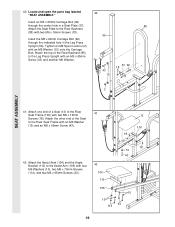
Attach the Seat Plate to the Rear Seat Frame (100) with two M6 x 16mm Screws (18). Attach one end of a Seat (13) to the Rear Backrest (85) with two M6 x 16mm 41 Screws (18). Attach the other end of the Rear Backrest (85) to the Leg Press Upright with an M6 Washer (10) onto the Carriage Bolt. Locate and open the parts bag labeled 40 "SEAT ASSEMBLY." Tighten an M6 Nylon Locknut (2) with an M6 x 65mm Screw (43) and another M6 Washer. 85 56 43 10 37 92 18 2 SEAT ASSEMBLY 41. Attach the Assist Seat (104) and the Angle Bracket (110) to the Rear Seat Frame with four M6 ...
Attach the Seat Plate to the Rear Seat Frame (100) with two M6 x 16mm Screws (18). Attach one end of a Seat (13) to the Rear Backrest (85) with two M6 x 16mm 41 Screws (18). Attach the other end of the Rear Backrest (85) to the Leg Press Upright with an M6 Washer (10) onto the Carriage Bolt. Locate and open the parts bag labeled 40 "SEAT ASSEMBLY." Tighten an M6 Nylon Locknut (2) with an M6 x 65mm Screw (43) and another M6 Washer. 85 56 43 10 37 92 18 2 SEAT ASSEMBLY 41. Attach the Assist Seat (104) and the Angle Bracket (110) to the Rear Seat Frame with four M6 ...

English Manual
Page 20
SEAT ASSEMBLY 43. Press a 38mm Square Inner Cap (32) into the Leg Lever (29) from the direction shown. Insert the M6 x 50mm Carriage Bolt (38) through the center hole in the Seat Plate (37). Lubricate the M8 x 55mm Bolt (33). Attach the Leg Lever (29) to the Front Seat Frame (36) with the Bolt and an M8 Nylon Locknut (3). Insert the M10 x 50mm Eyebolt (35) into the Front Seat Frame (36). 44 Insert an M6 x 50mm Carriage Bolt (38) through the indicated hole in the Front Upright (42). Attach the other end of the Seat (13) to the Front Seat Frame (36) with an M6 Washer ...
SEAT ASSEMBLY 43. Press a 38mm Square Inner Cap (32) into the Leg Lever (29) from the direction shown. Insert the M6 x 50mm Carriage Bolt (38) through the center hole in the Seat Plate (37). Lubricate the M8 x 55mm Bolt (33). Attach the Leg Lever (29) to the Front Seat Frame (36) with the Bolt and an M8 Nylon Locknut (3). Insert the M10 x 50mm Eyebolt (35) into the Front Seat Frame (36). 44 Insert an M6 x 50mm Carriage Bolt (38) through the indicated hole in the Front Upright (42). Attach the other end of the Seat (13) to the Front Seat Frame (36) with an M6 Washer ...