

English Manual
Page 2
...not use the lat bar. Make sure all instructions in this manual and in the locations shown on it. 17. Your hand could become pinched between the leg press upright and the military press arm. 16. Apply the decal in any exercise program, consult your body weight is missing or illegible... at any worn parts immediately. 6. Replace any time while exercising, stop immediately and make sure that does not use the weight system in the location shown. 10. Keep children under 12 and pets away from moving parts. 8. Always wear athletic shoes for persons over the age of 300 pounds...
...not use the lat bar. Make sure all instructions in this manual and in the locations shown on it. 17. Your hand could become pinched between the leg press upright and the military press arm. 16. Apply the decal in any exercise program, consult your body weight is missing or illegible... at any worn parts immediately. 6. Replace any time while exercising, stop immediately and make sure that does not use the weight system in the location shown. 10. Keep children under 12 and pets away from moving parts. 8. Always wear athletic shoes for persons over the age of 300 pounds...

English Manual
Page 4
... separately. • Wait until assembly is completed. • The assembly is not in the parts bag, check to open the parts bag labeled "FRAME ASSEMBLY." Locate and open the parts bag labeled for shipping. Insert two M8 x 65mm Carriage Bolts up through the Base (4). Assembly will also be needed. Note: Some... sure that you have been preattached for that assembly stage. • For help identifying the small parts used in assembly, use the PART IDENTIFICATION CHART located in the center of ratchet wrenches.
... separately. • Wait until assembly is completed. • The assembly is not in the parts bag, check to open the parts bag labeled "FRAME ASSEMBLY." Locate and open the parts bag labeled for shipping. Insert two M8 x 65mm Carriage Bolts up through the Base (4). Assembly will also be needed. Note: Some... sure that you have been preattached for that assembly stage. • For help identifying the small parts used in assembly, use the PART IDENTIFICATION CHART located in the center of ratchet wrenches.

English Manual
Page 8
...) with an M8 x 150mm Bolt (60), two 19.5mm Spacers (61), and an M8 Nylon Locknut (3). Make sure there is a Bushing (98) in the Base. Locate and open the parts bag labeled "ARM ASSEMBLY." Attach the upper ends of the Leg Press 10 Arm (96).
...) with an M8 x 150mm Bolt (60), two 19.5mm Spacers (61), and an M8 Nylon Locknut (3). Make sure there is a Bushing (98) in the Base. Locate and open the parts bag labeled "ARM ASSEMBLY." Attach the upper ends of the Leg Press 10 Arm (96).
English Manual
Page 11
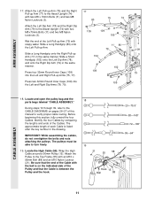
... is between the Pulley and the hook. 21 55 58 Hook 15 Ball 88 23-75.5" 58-148" 72-190" 99-64" CABLE ASSEMBLY 11 Locate the High Cable (58). Wrap the High Cable around a 90mm Pulley (15). Slide a Long Handgrip (80) onto the Left Pull-up Arm (75) with the... number in the drawing. Slide a Long Handgrip onto the Right Pull-up Arm (77) to turn freely. 19 19. The approximate length of the Cables. Locate and open the pulley bag and the parts bags labeled "CABLE ASSEMBLY." 18 During steps 19 through 39, refer to the CABLE DIAGRAMS on the...
... is between the Pulley and the hook. 21 55 58 Hook 15 Ball 88 23-75.5" 58-148" 72-190" 99-64" CABLE ASSEMBLY 11 Locate the High Cable (58). Wrap the High Cable around a 90mm Pulley (15). Slide a Long Handgrip (80) onto the Left Pull-up Arm (75) with the... number in the drawing. Slide a Long Handgrip onto the Right Pull-up Arm (77) to turn freely. 19 19. The approximate length of the Cables. Locate and open the pulley bag and the parts bags labeled "CABLE ASSEMBLY." 18 During steps 19 through 39, refer to the CABLE DIAGRAMS on the...
English Manual
Page 14
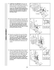
... the M10 x 85mm Bolt (not shown). 23 15 21 66 17 30. See the 42 15 inset drawing. Crossbar 21 15 23 Ball 17 28. Locate the Low Cable (23). See the inset drawing. Remove the indicated 90mm Pulley (15) from other side 14 Route the Low 27 Cable under a 90mm...
... the M10 x 85mm Bolt (not shown). 23 15 21 66 17 30. See the 42 15 inset drawing. Crossbar 21 15 23 Ball 17 28. Locate the Low Cable (23). See the inset drawing. Remove the indicated 90mm Pulley (15) from other side 14 Route the Low 27 Cable under a 90mm...
English Manual
Page 15
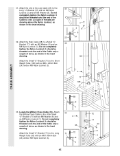
Do not completely tighten the Nylon Locknut. Locate the Military Press Cable (72). It should be threaded onto the end of the Cable only a couple of turns, as shown in the inset 63 ...
Do not completely tighten the Nylon Locknut. Locate the Military Press Cable (72). It should be threaded onto the end of the Cable only a couple of turns, as shown in the inset 63 ...
English Manual
Page 18
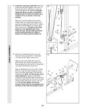
... must be threaded onto the end of the Cable only a couple of turns, as shown in the Rear Seat Frame (100) from the indicated side. Locate the Leg Press Cable (99). Slide an M8 Washer (8) onto an M8 x 75mm Bolt (93). Attach the Pulley to the Long "U"-
... must be threaded onto the end of the Cable only a couple of turns, as shown in the Rear Seat Frame (100) from the indicated side. Locate the Leg Press Cable (99). Slide an M8 Washer (8) onto an M8 x 75mm Bolt (93). Attach the Pulley to the Long "U"-
English Manual
Page 19
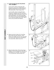
... 10 43 105 10 10 114 43 19 Insert the M6 x 60mm Carriage Bolt (92) through the center hole in the Leg Press Upright (56). Locate and open the parts bag labeled 40 "SEAT ASSEMBLY." 40.
... 10 43 105 10 10 114 43 19 Insert the M6 x 60mm Carriage Bolt (92) through the center hole in the Leg Press Upright (56). Locate and open the parts bag labeled 40 "SEAT ASSEMBLY." 40.
