
English Manual
Page 1
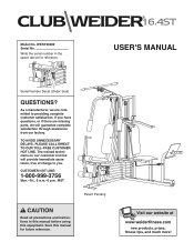
USER'S MANUAL Serial Number Decal (Under Seat) QUESTIONS? TO AVOID UNNECESSARY DELAYS, PLEASE CALL DIRECT TO OUR TOLL-FREE CUSTOMER HOT LINE. MST Patent Pending CAUTION Read all precautions and instructions in the space above for future reference. Write the serial number in this manual before using this manual for reference. As a manufacturer, we will provide immediate assistance, free of charge to providing complete customer satisfaction. WESY39200 Serial No. If you have questions, or if there are missing parts, we are committed to you. CUSTOMER HOT LINE: 1-800-999-3756 ...
USER'S MANUAL Serial Number Decal (Under Seat) QUESTIONS? TO AVOID UNNECESSARY DELAYS, PLEASE CALL DIRECT TO OUR TOLL-FREE CUSTOMER HOT LINE. MST Patent Pending CAUTION Read all precautions and instructions in the space above for future reference. Write the serial number in this manual before using this manual for reference. As a manufacturer, we will provide immediate assistance, free of charge to providing complete customer satisfaction. WESY39200 Serial No. If you have questions, or if there are missing parts, we are committed to you. CUSTOMER HOT LINE: 1-800-999-3756 ...
English Manual
Page 2
Remove the PART IDENTIFICATION CHART and the PART LIST/EXPLODED DRAWING before beginning assembly. WEIDER is a registered trademark of its authorized service centers with all other warranties and any implied warranties of merchantability or fitness for a particular purpose is limited ...
Remove the PART IDENTIFICATION CHART and the PART LIST/EXPLODED DRAWING before beginning assembly. WEIDER is a registered trademark of its authorized service centers with all other warranties and any implied warranties of merchantability or fitness for a particular purpose is limited ...
English Manual
Page 3
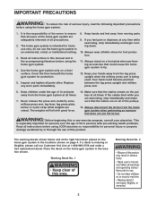
Read all instructions in this or any worn parts immediately. 8. If you are exercising, stop immediately and begin cooling down. 10. Always stand on a foot plate when performing an exercise that the cables remain on the pulleys at any time while exercising, stop immediately and make sure that the cables are on all instructions before using the home gym system. 4. Never release the press arm, butterfly arms, military press arm, leg lever, leg press plate, lat bar or nylon strap while weights are adequately informed of this area. 3 Make sure that could become pinched between ...
Read all instructions in this or any worn parts immediately. 8. If you are exercising, stop immediately and begin cooling down. 10. Always stand on a foot plate when performing an exercise that the cables remain on the pulleys at any time while exercising, stop immediately and make sure that the cables are on all instructions before using the home gym system. 4. Never release the press arm, butterfly arms, military press arm, leg lever, leg press plate, lat bar or nylon strap while weights are adequately informed of this area. 3 Make sure that could become pinched between ...
English Manual
Page 4
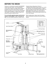
...Military Press Arm Backrests Leg Lever Leg Press Plate Low Pulley Station Foot Plate Weight Stacks Warning Decal No. 1 4 until 6 p.m. The CLUB WEIDER¨ 16.4ST offers a selection of weight stations designed to tone your body, build dramatic muscle size and strength, or improve your benefit, read this ...on a decal attached to achieve the specific results you , please note the product model number and serial number before using the CLUB WEIDER¨ 16.4ST home gym system. Lat Bar High Pulley Station Warning Decal No. 2 Butterfly Arms Press Arm Warning Decal No. 1 ASSEMBLED DIMENSIONS:...
...Military Press Arm Backrests Leg Lever Leg Press Plate Low Pulley Station Foot Plate Weight Stacks Warning Decal No. 1 4 until 6 p.m. The CLUB WEIDER¨ 16.4ST offers a selection of weight stations designed to tone your body, build dramatic muscle size and strength, or improve your benefit, read this ...on a decal attached to achieve the specific results you , please note the product model number and serial number before using the CLUB WEIDER¨ 16.4ST home gym system. Lat Bar High Pulley Station Warning Decal No. 2 Butterfly Arms Press Arm Warning Decal No. 1 ASSEMBLED DIMENSIONS:...
English Manual
Page 5
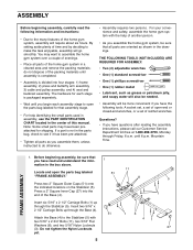
...shipping. For your convenience and safety, assemble the home gym system with two 5/16Ó x 2 3/4Ó Bolts (11), two 5/16Ó Flat Washers (8), and two 5/16Ó Nylon Locknuts (3). Insert six 5/16Ó x 2 1/2Ó Carriage Bolts (1) up through the Base (4). Attach...standard screwdriver ¥ One (1) phillips screwdriver ¥ One (1) rubber mallet ¥ Lubricant, such as shown in the drawings. FRAME ASSEMBLY 1. Insert two 5/16Ó x 2 1/2Ó Carriage Bolts up through Friday, 6 a.m. Press a 2Ó Square Inner Cap (27) into four stages: 1) frame assembly, ...
...shipping. For your convenience and safety, assemble the home gym system with two 5/16Ó x 2 3/4Ó Bolts (11), two 5/16Ó Flat Washers (8), and two 5/16Ó Nylon Locknuts (3). Insert six 5/16Ó x 2 1/2Ó Carriage Bolts (1) up through the Base (4). Attach...standard screwdriver ¥ One (1) phillips screwdriver ¥ One (1) rubber mallet ¥ Lubricant, such as shown in the drawings. FRAME ASSEMBLY 1. Insert two 5/16Ó x 2 1/2Ó Carriage Bolts up through Friday, 6 a.m. Press a 2Ó Square Inner Cap (27) into four stages: 1) frame assembly, ...

English Manual
Page 6
...Press a 2Ó Square Inner Cap into the Leg Press Upright (56). Do not tighten the Nylon Locknuts yet. Slide the Front Upright (42) onto the 5/16Ó x 2 1/2Ó Carriage Bolts (1) in the Stabilizer (5). Press a 2Ó Square Inner Cap (27) into the Rear Upright (74). Do not ...tighten the Nylon Locknuts yet. Hand tighten four 5/16Ó Nylon Locknuts (3) onto the Carriage Bolts. Press a 1Ó Square Inner Cap (6) into the Front Upright (42). Attach the Rubber Bumper (91)...
...Press a 2Ó Square Inner Cap into the Leg Press Upright (56). Do not tighten the Nylon Locknuts yet. Slide the Front Upright (42) onto the 5/16Ó x 2 1/2Ó Carriage Bolts (1) in the Stabilizer (5). Press a 2Ó Square Inner Cap (27) into the Rear Upright (74). Do not ...tighten the Nylon Locknuts yet. Hand tighten four 5/16Ó Nylon Locknuts (3) onto the Carriage Bolts. Press a 1Ó Square Inner Cap (6) into the Front Upright (42). Attach the Rubber Bumper (91)...
English Manual
Page 7
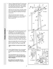
...Weight Bumpers (19) on the bracket on the Base (4) as shown. Be careful not to the Front Upright (42) with two 5/16Ó x 2 1/2Ó Carriage Bolts (1) and two 5/16Ó Nylon Locknuts (3). Attach the Top Frame (55) to tip either stack of Weights. Slide the Leg Press Seat Frame (79...) onto the indicated 5/16Ó x 2 1/2Ó Carriage Bolts (1) in steps 1Ð5. 5 56 8 3 1 79 11 3 3 1 82 5 6. Tighten all on the Top Frame. Set two Weight Bumpers (19)...
...Weight Bumpers (19) on the bracket on the Base (4) as shown. Be careful not to the Front Upright (42) with two 5/16Ó x 2 1/2Ó Carriage Bolts (1) and two 5/16Ó Nylon Locknuts (3). Attach the Top Frame (55) to tip either stack of Weights. Slide the Leg Press Seat Frame (79...) onto the indicated 5/16Ó x 2 1/2Ó Carriage Bolts (1) in steps 1Ð5. 5 56 8 3 1 79 11 3 3 1 82 5 6. Tighten all on the Top Frame. Set two Weight Bumpers (19)...
English Manual
Page 8
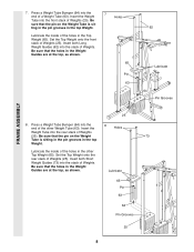
Insert both Short Weight Guides (73) into the end of Weights (25). Be sure that the holes in the Weight Guides are at the top, as shown. Lubricate the inside of the other Top Weight (65). Insert the 8 Holes Weight Tube into the stack of Weights (25). Lubricate 65 Pin 63 64 Pin Grooves 25 8 ting in the pin grooves in the other Weight Tube (63). Be sure that the holes in the Weight Guides are at the top, as shown. 65 Pin 63 62 Lubricate 64 Pin Grooves FRAME ASSEMBLY 25 8. Be sure that the pin on the Weight Tube is sitting in...
Insert both Short Weight Guides (73) into the end of Weights (25). Be sure that the holes in the Weight Guides are at the top, as shown. Lubricate the inside of the other Top Weight (65). Insert the 8 Holes Weight Tube into the stack of Weights (25). Lubricate 65 Pin 63 64 Pin Grooves 25 8 ting in the pin grooves in the other Weight Tube (63). Be sure that the holes in the Weight Guides are at the top, as shown. 65 Pin 63 62 Lubricate 64 Pin Grooves FRAME ASSEMBLY 25 8. Be sure that the pin on the Weight Tube is sitting in...

English Manual
Page 9
... a 3/8Ó x 3 1/4Ó Bolt (67). Attach the Press Frame (17) to the Leg Press Arm with a 5/16Ó x 6Ó Bolt (60), two 1/2Ó x 3/4Ó Spacers (61), and a 5/16Ó Nylon Locknut (3). Align the welded tubes on the Press Frame (17). Attach the Leg Press Plate to the Base...) onto each end of the Leg Press Arm (96). Note: This will be able to the Stabilizer (5) with a 5/16Ó x 6Ó Bolt (60), two 1/2Ó x 3/4Ó Spacers (61), and a 5/16Ó Nylon Locknut (3). Attach the Leg Press Arm (96) to pivot freely. Lubricate the 3/8Ó x 8Ó Bolt...
... a 3/8Ó x 3 1/4Ó Bolt (67). Attach the Press Frame (17) to the Leg Press Arm with a 5/16Ó x 6Ó Bolt (60), two 1/2Ó x 3/4Ó Spacers (61), and a 5/16Ó Nylon Locknut (3). Align the welded tubes on the Press Frame (17). Attach the Leg Press Plate to the Base...) onto each end of the Leg Press Arm (96). Note: This will be able to the Stabilizer (5) with a 5/16Ó x 6Ó Bolt (60), two 1/2Ó x 3/4Ó Spacers (61), and a 5/16Ó Nylon Locknut (3). Attach the Leg Press Arm (96) to pivot freely. Lubricate the 3/8Ó x 8Ó Bolt...

English Manual
Page 10
... (17) with a 3/8Ó x 2 1/2Ó Bolt (86) and a 3/8Ó Nylon Locknut (21). Note: Be careful not to the Right Arm (48) with two 5/16Ó x 2 1/2Ó Bolts (22) and two 5/16Ó Nylon Locknuts (3). 22 Assemble the other Press Arm (46) in the same manner. 46 3 17 13. refer to step 13 to...
... (17) with a 3/8Ó x 2 1/2Ó Bolt (86) and a 3/8Ó Nylon Locknut (21). Note: Be careful not to the Right Arm (48) with two 5/16Ó x 2 1/2Ó Bolts (22) and two 5/16Ó Nylon Locknuts (3). 22 Assemble the other Press Arm (46) in the same manner. 46 3 17 13. refer to step 13 to...
English Manual
Page 11
...The approximate length of the Military Press Arm (84). Attach the Military 15 Press Arm (84) to the Rear Upright (74) with two 5/16Ó x 2 1/4Ó Bolts (33) and two 5/16Ó Nylon Locknuts (3). Attach the Pivot Arm (80) to the Pivot Arm (80) with the Bolt and a 3/8Ó Nylon Locknut (21...). 74 32 49 32 84 80 67 56 ARM ASSEMBLY CABLE ASSEMBLY 33 16. Identify the four Cables by comparing the lengths and ends of the Cable with a 3/8Ó x 3 3/4Ó Bolt (88) and a 3/8Ó Nylon Locknut (21)....
...The approximate length of the Military Press Arm (84). Attach the Military 15 Press Arm (84) to the Rear Upright (74) with two 5/16Ó x 2 1/4Ó Bolts (33) and two 5/16Ó Nylon Locknuts (3). Attach the Pivot Arm (80) to the Pivot Arm (80) with the Bolt and a 3/8Ó Nylon Locknut (21...). 74 32 49 32 84 80 67 56 ARM ASSEMBLY CABLE ASSEMBLY 33 16. Identify the four Cables by comparing the lengths and ends of the Cable with a 3/8Ó x 3 3/4Ó Bolt (88) and a 3/8Ó Nylon Locknut (21)....

English Manual
Page 12
...; Nylon Locknut (not shown). Wrap the High Cable (58) around the ÒVÓPulley (50) on the Front Upright (42) with the 5/16Ó x 5Ó Bolt (68) and a 68 5/16Ó Nylon Locknut (3). Pulley and that the Long Cable Trap is turned to hold the Cable in place. 12 Be sure that...
...; Nylon Locknut (not shown). Wrap the High Cable (58) around the ÒVÓPulley (50) on the Front Upright (42) with the 5/16Ó x 5Ó Bolt (68) and a 68 5/16Ó Nylon Locknut (3). Pulley and that the Long Cable Trap is turned to hold the Cable in place. 12 Be sure that...

English Manual
Page 13
... Cable (58) around a 3 1/2Ó Pulley (15). Attach the Small ÒUÓ-Bracket (71) to the bracket on the Top Frame (55) with a 5/16Ó x 1 3/4Ó Bolt (24) and a 5/16Ó Nylon Locknut (3). 3 71 63 58 71 10 2 13 24 10 2 22. Note: This may come pre-assembled. Attach the High Cable (58...
... Cable (58) around a 3 1/2Ó Pulley (15). Attach the Small ÒUÓ-Bracket (71) to the bracket on the Top Frame (55) with a 5/16Ó x 1 3/4Ó Bolt (24) and a 5/16Ó Nylon Locknut (3). 3 71 63 58 71 10 2 13 24 10 2 22. Note: This may come pre-assembled. Attach the High Cable (58...

English Manual
Page 14
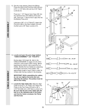
...23) and the bag labeled ÒLOW PULLEY.Ó Route the Low Cable under the 3 1/2Ó Low Pulley (76). Attach the Pulley and the 5/8Ó x 9/16Ó Spacer (7) to hold the Cable in the drawing, and that the Cable is routed around the Pulley as shown. 88 9 42 66 21 15... other side 88 9 14 Attach the Pulley and a Cable Trap (66) to hold the Cable in the Front Upright (42) with a 3/8Ó x 3 1/2Ó Bolt (16), a 3/8Ó Flat Washer (9), and a 3/8Ó Nylon Locknut (21). See the inset drawing. Be sure that the Cable Trap is turned to the upper hole in...
...23) and the bag labeled ÒLOW PULLEY.Ó Route the Low Cable under the 3 1/2Ó Low Pulley (76). Attach the Pulley and the 5/8Ó x 9/16Ó Spacer (7) to hold the Cable in the drawing, and that the Cable is routed around the Pulley as shown. 88 9 42 66 21 15... other side 88 9 14 Attach the Pulley and a Cable Trap (66) to hold the Cable in the Front Upright (42) with a 3/8Ó x 3 1/2Ó Bolt (16), a 3/8Ó Flat Washer (9), and a 3/8Ó Nylon Locknut (21). See the inset drawing. Be sure that the Cable Trap is turned to the upper hole in...

English Manual
Page 15
...; x 2Ó Bolt (12) and a 3/8Ó Nylon Locknut (21). Attach the Small ÒUÓ-Bracket (71) to the Long ÒUÓ-Bracket (57) with a 5/16Ó x 1 3/4Ó Bolt (24) and a 5/16Ó Nylon Locknut (3). 31. Wrap the Military Press Cable (72) around a 3 1/2Ó Pulley (15). Wrap the Military Press Cable (72) around a 3 1/2Ó...
...; x 2Ó Bolt (12) and a 3/8Ó Nylon Locknut (21). Attach the Small ÒUÓ-Bracket (71) to the Long ÒUÓ-Bracket (57) with a 5/16Ó x 1 3/4Ó Bolt (24) and a 5/16Ó Nylon Locknut (3). 31. Wrap the Military Press Cable (72) around a 3 1/2Ó Pulley (15). Wrap the Military Press Cable (72) around a 3 1/2Ó...

English Manual
Page 16
...) with a 3/8Ó Nylon Locknut (21). Be sure the Cable Trap is in place, and that the Cable and Pulley move smoothly. See the inset drawing. 16 99 72 9 Post 15 77 9 88 Large tabs must be in place. 32 15 101 66 72 57 33 21 80 66 21 15 21...
...) with a 3/8Ó Nylon Locknut (21). Be sure the Cable Trap is in place, and that the Cable and Pulley move smoothly. See the inset drawing. 16 99 72 9 Post 15 77 9 88 Large tabs must be in place. 32 15 101 66 72 57 33 21 80 66 21 15 21...

English Manual
Page 17
.... Be sure that the Cable and Pulley move smoothly and that the Cable is between the two Jam Nuts for cable adjustment.) Tighten a 5/16Ó Flat Washer (8) and a 5/16Ó Nylon Jam Nut (93) onto the Bolt. Wrap the Leg Press Cable (78) around a 3 1/2Ó Pulley (15). Attach the Pulley to pivot...;UÓBracket (57) with a 3/8Ó x 3Ó Bolt (100) and 36 a 3/8Ó Nylon Jam Nut (99). Do not fully tighten the second Jam Nut. Thread another 5/16Ó Nylon Jam Nut (93) onto the Bolt. It should be room between the Pulley and the welded rod. Slide the end of the Leg...
.... Be sure that the Cable and Pulley move smoothly and that the Cable is between the two Jam Nuts for cable adjustment.) Tighten a 5/16Ó Flat Washer (8) and a 5/16Ó Nylon Jam Nut (93) onto the Bolt. Wrap the Leg Press Cable (78) around a 3 1/2Ó Pulley (15). Attach the Pulley to pivot...;UÓBracket (57) with a 3/8Ó x 3Ó Bolt (100) and 36 a 3/8Ó Nylon Jam Nut (99). Do not fully tighten the second Jam Nut. Thread another 5/16Ó Nylon Jam Nut (93) onto the Bolt. It should be room between the Pulley and the welded rod. Slide the end of the Leg...

English Manual
Page 18
Locate and open the parts bag labeled ÒSEAT ASSEMBLY.Ó Insert a 1/4Ó x 2 1/2Ó Carriage Bolt (92) through the indicated hole in a Seat Plate (37). Insert the 1/4Ó x 2 1/2Ó Carriage Bolt (92) through the center hole in the Leg Press Upright (56). Attach one end of the Seat to the Leg Press Seat Frame with a 1/4Ó Flat Washer (10) and a 1/4Ó x 2 1/2Ó Screw (43). 37 85 56 10 43 37 18 92 2 38 13 18 SEAT ASSEMBLY 39. Insert the 1/4Ó x 2Ó Carriage Bolt (38) through 40 the center hole in the Front Seat Frame (36). ...
Locate and open the parts bag labeled ÒSEAT ASSEMBLY.Ó Insert a 1/4Ó x 2 1/2Ó Carriage Bolt (92) through the indicated hole in a Seat Plate (37). Insert the 1/4Ó x 2 1/2Ó Carriage Bolt (92) through the center hole in the Leg Press Upright (56). Attach one end of the Seat to the Leg Press Seat Frame with a 1/4Ó Flat Washer (10) and a 1/4Ó x 2 1/2Ó Screw (43). 37 85 56 10 43 37 18 92 2 38 13 18 SEAT ASSEMBLY 39. Insert the 1/4Ó x 2Ó Carriage Bolt (38) through 40 the center hole in the Front Seat Frame (36). ...

English Manual
Page 19
... Pad (30) onto each Pad Tube (28). 43 Insert a Pad Tube (28) into the Leg Lever (29). Tighten a 5/16Ó Nylon Locknut (3) with the Bolt and a 5/16Ó Nylon Locknut (3). Insert the 5/16Ó x 2Ó Eyebolt (35) into the 41 Leg Lever (29). Rest the Front Seat Frame (36) on the indicat...42). Insert the other Pad Tube (28) into the Front Seat Frame (36). Attach the Leg Lever (29) to the Front Upright with a 5/16Ó x 2 3/4Ó Carriage Bolt (14), 3/16Ó Flat Washer (8), and the Seat Knob (40). 33 35 32 36 3 29 8 3 42 40 8 14 36 Pin 43. SEAT ASSEMBLY...
... Pad (30) onto each Pad Tube (28). 43 Insert a Pad Tube (28) into the Leg Lever (29). Tighten a 5/16Ó Nylon Locknut (3) with the Bolt and a 5/16Ó Nylon Locknut (3). Insert the 5/16Ó x 2Ó Eyebolt (35) into the 41 Leg Lever (29). Rest the Front Seat Frame (36) on the indicat...42). Insert the other Pad Tube (28) into the Front Seat Frame (36). Attach the Leg Lever (29) to the Front Upright with a 5/16Ó x 2 3/4Ó Carriage Bolt (14), 3/16Ó Flat Washer (8), and the Seat Knob (40). 33 35 32 36 3 29 8 3 42 40 8 14 36 Pin 43. SEAT ASSEMBLY...
English Manual
Page 20
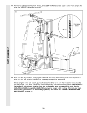
The use of the cables does not move smoothly over the pulleys. If there is used. Remove the adhesive backing from the CLUB WEIDER¨ 16.4ST decal and apply it by tightening the cables. If one of the remaining parts will need to remove it to be sure that all parts ... CABLE DIAGRAMS on page 24. 20 Before using the home gym system, pull each cable a few times to the Front Upright (42) under the ÒWEIDERÓ nameplate as shown. 44 PRO 9400 Decal 42 42 45.
The use of the cables does not move smoothly over the pulleys. If there is used. Remove the adhesive backing from the CLUB WEIDER¨ 16.4ST decal and apply it by tightening the cables. If one of the remaining parts will need to remove it to be sure that all parts ... CABLE DIAGRAMS on page 24. 20 Before using the home gym system, pull each cable a few times to the Front Upright (42) under the ÒWEIDERÓ nameplate as shown. 44 PRO 9400 Decal 42 42 45.