
English Manual
Page 1
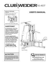
..., free of charge to you have questions, or if there are committed to providing complete customer satisfaction. Save this equipment. Visit our website at www.weiderfitness.com new products, prizes, fitness tips, and much more! MST Patent Pending CAUTION Read all precautions and instructions in the space above for future reference. USER'S MANUAL Serial Number Decal (Under Seat) QUESTIONS...
..., free of charge to you have questions, or if there are committed to providing complete customer satisfaction. Save this equipment. Visit our website at www.weiderfitness.com new products, prizes, fitness tips, and much more! MST Patent Pending CAUTION Read all precautions and instructions in the space above for future reference. USER'S MANUAL Serial Number Decal (Under Seat) QUESTIONS...
English Manual
Page 2
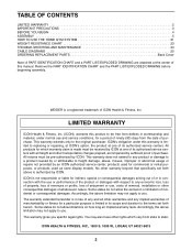
... consequential damages arising out of purchase. TABLE OF CONTENTS LIMITED WARRANTY 2 IMPORTANT PRECAUTIONS 3 BEFORE YOU BEGIN 4 ASSEMBLY 5 HOW TO USE THE HOME GYM SYSTEM 21 WEIGHT RESISTANCE CHART 23 TROUBLE-SHOOTING AND MAINTENANCE 24 CABLE DIAGRAMS 25 ORDERING REPLACEMENT PARTS Back Cover Note: A PART IDENTIFICATION CHART and a PART LIST/EXPLODED DRAWING are attached at the center of this warranty is limited in its authorized service centers. All products for which vary from the date...
... consequential damages arising out of purchase. TABLE OF CONTENTS LIMITED WARRANTY 2 IMPORTANT PRECAUTIONS 3 BEFORE YOU BEGIN 4 ASSEMBLY 5 HOW TO USE THE HOME GYM SYSTEM 21 WEIGHT RESISTANCE CHART 23 TROUBLE-SHOOTING AND MAINTENANCE 24 CABLE DIAGRAMS 25 ORDERING REPLACEMENT PARTS Back Cover Note: A PART IDENTIFICATION CHART and a PART LIST/EXPLODED DRAWING are attached at the center of this warranty is limited in its authorized service centers. All products for which vary from the date...
English Manual
Page 3
... parts immediately. 8. Place the decal on the pulleys at any time while exercising, stop immediately and make sure that all users of the home gym system are raised. Never release the press arm, butterfly arms, military press arm, leg lever, leg press plate, lat bar or nylon strap while weights are adequately informed of all times. ICON assumes no responsibility for home use of 12 and pets away from the leg press upright when the military press arm...
... parts immediately. 8. Place the decal on the pulleys at any time while exercising, stop immediately and make sure that all users of the home gym system are raised. Never release the press arm, butterfly arms, military press arm, leg lever, leg press plate, lat bar or nylon strap while weights are adequately informed of all times. ICON assumes no responsibility for home use of 12 and pets away from the leg press upright when the military press arm...
English Manual
Page 4
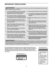
... the versatile CLUB WEIDER¨ 16.4ST home gym system. The model number is to tone your body, build dramatic muscle size and strength, or improve your benefit, read this manual). Lat Bar High Pulley Station Warning Decal No. 2 Butterfly Arms Press Arm Warning Decal No. 1 ASSEMBLED DIMENSIONS: Height: 76 in . Length: 64 in . If you , please note the product model number and serial number before using the CLUB WEIDER¨ 16.4ST home gym system. Customer Service Department toll-free at...
... the versatile CLUB WEIDER¨ 16.4ST home gym system. The model number is to tone your body, build dramatic muscle size and strength, or improve your benefit, read this manual). Lat Bar High Pulley Station Warning Decal No. 2 Butterfly Arms Press Arm Warning Decal No. 1 ASSEMBLED DIMENSIONS: Height: 76 in . Length: 64 in . If you , please note the product model number and serial number before using the CLUB WEIDER¨ 16.4ST home gym system. Customer Service Department toll-free at...
English Manual
Page 5
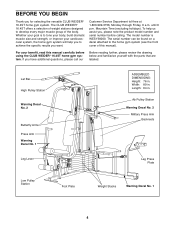
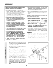
... four stages: 1) frame assembly, 2) press and butterfly arm assembly, 3) cable and pulley assembly, and 4) seat and backrest assembly. The hardware for each assembly stage to the many features of the home gym system in the drawings. Note: Some small parts may want to make the task enjoyable, assembly will require about six hours. Mountain Time. Insert six 5/16Ó x 2 1/2Ó Carriage Bolts (1) up through the Base...
... four stages: 1) frame assembly, 2) press and butterfly arm assembly, 3) cable and pulley assembly, and 4) seat and backrest assembly. The hardware for each assembly stage to the many features of the home gym system in the drawings. Note: Some small parts may want to make the task enjoyable, assembly will require about six hours. Mountain Time. Insert six 5/16Ó x 2 1/2Ó Carriage Bolts (1) up through the Base...

English Manual
Page 6
... the Rear Upright and Leg Press Upright should be on the side shown. Press a 1Ó Square Inner Cap (6) into the Front Upright (42). The high side of Brackets 56 5 1 1 3. Slide the Front Upright (42) onto the 5/16Ó x 2 1/2Ó Carriage Bolts (1) in the Stabilizer (5). Hand tighten four 5/16Ó Nylon Locknuts (3) onto the Carriage Bolts. 2. FRAME ASSEMBLY 4 1 42 6 3 6 Slide the Rear Upright (74) and the Leg Press Upright (56...
... the Rear Upright and Leg Press Upright should be on the side shown. Press a 1Ó Square Inner Cap (6) into the Front Upright (42). The high side of Brackets 56 5 1 1 3. Slide the Front Upright (42) onto the 5/16Ó x 2 1/2Ó Carriage Bolts (1) in the Stabilizer (5). Hand tighten four 5/16Ó Nylon Locknuts (3) onto the Carriage Bolts. 2. FRAME ASSEMBLY 4 1 42 6 3 6 Slide the Rear Upright (74) and the Leg Press Upright (56...
English Manual
Page 7
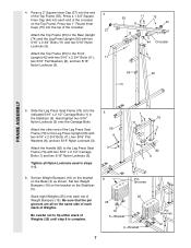
... pin grooves are all Nylon Locknuts used in the Stabilizer (5). Tighten all on the Top Frame. Slide the Leg Press Seat Frame (79) onto the indicated 5/16Ó x 2 1/2Ó Carriage Bolts (1) in steps 1Ð5. 5 56 8 3 1 79 11 3 3 1 82 5 6. Be careful not to the Rear Upright (74) and the Leg Press Upright (56) with two 5/16Ó x 2 3/4Ó Bolts (11), 11 two 5/16Ó Flat Washers (8), and two 5/16...
... pin grooves are all Nylon Locknuts used in the Stabilizer (5). Tighten all on the Top Frame. Slide the Leg Press Seat Frame (79) onto the indicated 5/16Ó x 2 1/2Ó Carriage Bolts (1) in steps 1Ð5. 5 56 8 3 1 79 11 3 3 1 82 5 6. Be careful not to the Rear Upright (74) and the Leg Press Upright (56) with two 5/16Ó x 2 3/4Ó Bolts (11), 11 two 5/16Ó Flat Washers (8), and two 5/16...

English Manual
Page 9
... Nylon Locknut. Locate and open the parts bag labeled ÒARM ASSEMBLY.Ó Be sure there is a Bushing (98) in the Leg Press Arm (96). Press a 2Ó Square Inner Cap (27) into place onto the Base (4). Lubricate a 3/8Ó x 3 1/4Ó Bolt (67). The Leg Press Arm must be on the Leg Press Plate (95) with one set of the Long Weight Guides (62) to the Leg Press Arm with a 5/16Ó x 6Ó Bolt (60), two...
... Nylon Locknut. Locate and open the parts bag labeled ÒARM ASSEMBLY.Ó Be sure there is a Bushing (98) in the Leg Press Arm (96). Press a 2Ó Square Inner Cap (27) into place onto the Base (4). Lubricate a 3/8Ó x 3 1/4Ó Bolt (67). The Leg Press Arm must be on the Leg Press Plate (95) with one set of the Long Weight Guides (62) to the Leg Press Arm with a 5/16Ó x 6Ó Bolt (60), two...
English Manual
Page 11
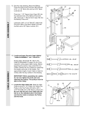
... Cable around a 3 1/2Ó Pulley (15). Lubricate a 3/8Ó x 3 1/4Ó Bolt (67). See the inset drawing. Press two 1 1/2Ó Square Inner Caps (32) into 21 the Military Press Arm. IMPORTANT: While assembling the cables, do not over tighten the bolts and nuts attaching the pulleys. Be sure that the end of the Pulley and that the Cable is listed (in inches) after the key number in the drawing. Attach the Pivot Arm...
... Cable around a 3 1/2Ó Pulley (15). Lubricate a 3/8Ó x 3 1/4Ó Bolt (67). See the inset drawing. Press two 1 1/2Ó Square Inner Caps (32) into 21 the Military Press Arm. IMPORTANT: While assembling the cables, do not over tighten the bolts and nuts attaching the pulleys. Be sure that the end of the Pulley and that the Cable is listed (in inches) after the key number in the drawing. Attach the Pivot Arm...

English Manual
Page 12
...;- Attach the ÒVÓ-Pulley and a Long Cable Trap (31) to hold the Cable in place. 19. Tighten the 3/8Ó x 2 1/2Ó Bolt (86) and the 3/8Ó Nylon Locknut (not shown). 58 31 86 50 48 CABLE ASSEMBLY 21. Route the High Cable 55 66 (58) around the ÒVÓ- 20 Pulley (50) on the Front Upright (42) with the 5/16Ó x 5Ó Bolt (68...
...;- Attach the ÒVÓ-Pulley and a Long Cable Trap (31) to hold the Cable in place. 19. Tighten the 3/8Ó x 2 1/2Ó Bolt (86) and the 3/8Ó Nylon Locknut (not shown). 58 31 86 50 48 CABLE ASSEMBLY 21. Route the High Cable 55 66 (58) around the ÒVÓ- 20 Pulley (50) on the Front Upright (42) with the 5/16Ó x 5Ó Bolt (68...

English Manual
Page 15
... may need to lift the Top Weight (not shown) on the Stabilizer (5) with a 3/8Ó x 2Ó Bolt (12) and a 3/8Ó Nylon Locknut (21). Do not completely tighten the Nylon Locknut. Attach the Pulley to the Top Frame (55) with a 3/8Ó x 2Ó Bolt (12) and a 3/8Ó Nylon Locknut (21). Locate the Military Press Cable (72). Wrap the Military Press Cable (72) around a 3 1/2Ó Pulley (15). CABLE ASSEMBLY...
... may need to lift the Top Weight (not shown) on the Stabilizer (5) with a 3/8Ó x 2Ó Bolt (12) and a 3/8Ó Nylon Locknut (21). Do not completely tighten the Nylon Locknut. Attach the Pulley to the Top Frame (55) with a 3/8Ó x 2Ó Bolt (12) and a 3/8Ó Nylon Locknut (21). Locate the Military Press Cable (72). Wrap the Military Press Cable (72) around a 3 1/2Ó Pulley (15). CABLE ASSEMBLY...

English Manual
Page 17
... (21). Attach the end of the Bolt. Slide a 5/16Ó Flat Washer (8) onto a 5/16Ó x 2 3/4Ó Bolt (11). Thread another 5/16Ó Nylon Jam Nut (93) onto the Bolt. Be sure that the Cable and Pulley move smoothly and that the Cable is between the two Jam Nuts for cable adjustment.) Tighten a 5/16Ó Flat Washer (8) and a 5/16Ó Nylon Jam Nut (93) onto the Bolt. CABLE ASSEMBLY 35.
... (21). Attach the end of the Bolt. Slide a 5/16Ó Flat Washer (8) onto a 5/16Ó x 2 3/4Ó Bolt (11). Thread another 5/16Ó Nylon Jam Nut (93) onto the Bolt. Be sure that the Cable and Pulley move smoothly and that the Cable is between the two Jam Nuts for cable adjustment.) Tighten a 5/16Ó Flat Washer (8) and a 5/16Ó Nylon Jam Nut (93) onto the Bolt. CABLE ASSEMBLY 35.

English Manual
Page 18
... in the Leg Press Upright (56). Locate and open the parts bag labeled ÒSEAT ASSEMBLY.Ó Insert a 1/4Ó x 2 1/2Ó Carriage Bolt (92) through the indicated hole in a Seat Plate (37). Attach the Seat Plate to the Front Upright (42) with a 1/4Ó x 2 1/2Ó Screw (43) and a 1/4Ó Flat Washer (10). 38. Attach the other end of the Seat to the Leg Press Upright with two 1/4Ó x 2 1/2Ó Screws (43) and...
... in the Leg Press Upright (56). Locate and open the parts bag labeled ÒSEAT ASSEMBLY.Ó Insert a 1/4Ó x 2 1/2Ó Carriage Bolt (92) through the indicated hole in a Seat Plate (37). Attach the Seat Plate to the Front Upright (42) with a 1/4Ó x 2 1/2Ó Screw (43) and a 1/4Ó Flat Washer (10). 38. Attach the other end of the Seat to the Leg Press Upright with two 1/4Ó x 2 1/2Ó Screws (43) and...
English Manual
Page 20
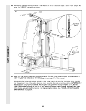
... CLUB WEIDER¨ 16.4ST decal and apply it by tightening the cables. See the CABLE DIAGRAMS on page 25 and 26 of the remaining parts will be explained in the cables, you will need to remove it to be damaged when heavy weight is any slack in HOW TO USE THE HOME GYM SYSTEM, beginning on page 24. 20 If there is used. SEAT ASSEMBLY 44. Before using the home gym...
... CLUB WEIDER¨ 16.4ST decal and apply it by tightening the cables. See the CABLE DIAGRAMS on page 25 and 26 of the remaining parts will be explained in the cables, you will need to remove it to be damaged when heavy weight is any slack in HOW TO USE THE HOME GYM SYSTEM, beginning on page 24. 20 If there is used. SEAT ASSEMBLY 44. Before using the home gym...
English Manual
Page 21
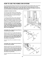
... correct starting position for each weight station. 25 26 ATTACHING THE LAT BAR OR NYLON STRAP TO THE HIGH PULLEY STATION Attach the Lat Bar (54) to find the approximate amount of resistance at each part of the Chain between the Lat Bar and the Low Cable so the Lat Bar is touching the Weights, and turn the bent end downward. Adjust the length of the home gym system can be adjusted. The weight setting...
... correct starting position for each weight station. 25 26 ATTACHING THE LAT BAR OR NYLON STRAP TO THE HIGH PULLEY STATION Attach the Lat Bar (54) to find the approximate amount of resistance at each part of the Chain between the Lat Bar and the Low Cable so the Lat Bar is touching the Weights, and turn the bent end downward. Adjust the length of the home gym system can be adjusted. The weight setting...

English Manual
Page 22
... Seat Knob (40), 3/16Ó Flat Washer (8) and the 5/16Ó x 2 3/4Ó Carriage Bolt (14) from the Leg Press Plate (95) and the Leg Press Arm (96). ADJUSTING THE LEG PRESS PLATE Remove the Press Pin (97) from the Front Seat Frame (36). Re-insert the Press Pin (97) through the welded tubes on the Front Upright (42). Attach one end of the Chain to the Low Cable (23) with the desired set...
... Seat Knob (40), 3/16Ó Flat Washer (8) and the 5/16Ó x 2 3/4Ó Carriage Bolt (14) from the Leg Press Plate (95) and the Leg Press Arm (96). ADJUSTING THE LEG PRESS PLATE Remove the Press Pin (97) from the Front Seat Frame (36). Re-insert the Press Pin (97) through the welded tubes on the Front Upright (42). Attach one end of the Chain to the Low Cable (23) with the desired set...

English Manual
Page 23
... arm resistance listed is the resistance for each weight station may vary due to differences in individual weight plates, as well as friction between the cables, pulleys, and weight guides. WEIGHT RESISTANCE CHART This chart shows the approximate weight resistance at each butterfly arm. The other numbers refer to the 6.5 lb. The actual resistance at each weight station. ÒTopÓ refers to the 12.5 lb. WEIGHT PLATES PRESS BUTTERFLY ARM ARM (lbs.) (lbs.) LEG...
... arm resistance listed is the resistance for each weight station may vary due to differences in individual weight plates, as well as friction between the cables, pulleys, and weight guides. WEIGHT RESISTANCE CHART This chart shows the approximate weight resistance at each butterfly arm. The other numbers refer to the 6.5 lb. The actual resistance at each weight station. ÒTopÓ refers to the 12.5 lb. WEIGHT PLATES PRESS BUTTERFLY ARM ARM (lbs.) (lbs.) LEG...
English Manual
Page 24
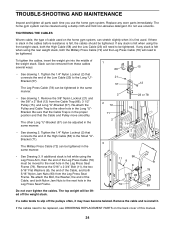
... tighten the cables. Remove the cable and re-install it. TROUBLE-SHOOTING AND MAINTENANCE Inspect and tighten all parts each time you use solvents. Replace any slack is in the Leg Press Seat Frame. If there is slack in the Long ÒUÓBracket. Tighten the 1/4Ó Nylon Locknut (2) that the Cable and Pulley move smoothly. Remove the 3/8Ó Nylon Locknut (21) and the 3/8Ó x 2Ó Bolt (12) from the Leg Press Seat...
... tighten the cables. Remove the cable and re-install it. TROUBLE-SHOOTING AND MAINTENANCE Inspect and tighten all parts each time you use solvents. Replace any slack is in the Leg Press Seat Frame. If there is slack in the Long ÒUÓBracket. Tighten the 1/4Ó Nylon Locknut (2) that the Cable and Pulley move smoothly. Remove the 3/8Ó Nylon Locknut (21) and the 3/8Ó x 2Ó Bolt (12) from the Leg Press Seat...
English Manual
Page 31
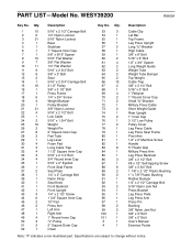
... Cable Clip Lat Bar Top Frame Leg Press Upright Long ÒUÓ-Bracket High Cable 3/8Ó x 8Ó Bolt 5/16Ó x 6Ó Bolt 1/2Ó x 3/4Ó Spacer Long Weight Guide Weight Tube Weight Tube Bumper Top Weight Cable Trap 3/8Ó x 3 1/4Ó Bolt 5/16Ó x 5Ó Bolt 1Ó Retainer 1Ó Round Cover Cap Small ÒUÓ-Bracket Military Press Cable Short Weight Guide Rear Upright 1Ó Inner Cap 3 1/2Ó Low Pulley Pulley Cover Leg Press Cable Leg Press Seat Frame Pivot Arm 1/4Ó x 2Ó Machine Screw Handle 5Ó Plastic Grip Military Press Arm Leg...
... Cable Clip Lat Bar Top Frame Leg Press Upright Long ÒUÓ-Bracket High Cable 3/8Ó x 8Ó Bolt 5/16Ó x 6Ó Bolt 1/2Ó x 3/4Ó Spacer Long Weight Guide Weight Tube Weight Tube Bumper Top Weight Cable Trap 3/8Ó x 3 1/4Ó Bolt 5/16Ó x 5Ó Bolt 1Ó Retainer 1Ó Round Cover Cap Small ÒUÓ-Bracket Military Press Cable Short Weight Guide Rear Upright 1Ó Inner Cap 3 1/2Ó Low Pulley Pulley Cover Leg Press Cable Leg Press Seat Frame Pivot Arm 1/4Ó x 2Ó Machine Screw Handle 5Ó Plastic Grip Military Press Arm Leg...
English Manual
Page 33
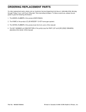
... Printed in Canada © 2000 ICON Health & Fitness, Inc. ORDERING REPLACEMENT PARTS To order replacement parts, simply call our Customer Service Department toll-free at the center of this manual) 4. The MODEL NUMBER of the part(s) (see the front cover of the product (CLUB WEIDER¨ 16.4ST home gym system) 3. To help us assist you, please be prepared to give the following information: 1. The KEY NUMBER and DESCRIPTION of the product (WESY39200...
... Printed in Canada © 2000 ICON Health & Fitness, Inc. ORDERING REPLACEMENT PARTS To order replacement parts, simply call our Customer Service Department toll-free at the center of this manual) 4. The MODEL NUMBER of the part(s) (see the front cover of the product (CLUB WEIDER¨ 16.4ST home gym system) 3. To help us assist you, please be prepared to give the following information: 1. The KEY NUMBER and DESCRIPTION of the product (WESY39200...


