
English Manual
Page 3
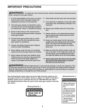
...rental, or institutional setting. 3. Your hand could cause the home gym system to ensure that does not use the home gym system in the location shown. Inspect and tighten all users of the home gym system are raised. Replace any time while exercising, stop immediately and make sure that ...exercising, stop immediately and begin cooling down. 10. Warning Decal No. 1 Warning Decal No. 2 ¥ Keep clear of this manual and in the locations shown on a level surface. do not use the lat bar. Make sure that the cables are on the pulleys at the right have been placed...
...rental, or institutional setting. 3. Your hand could cause the home gym system to ensure that does not use the home gym system in the location shown. Inspect and tighten all users of the home gym system are raised. Replace any time while exercising, stop immediately and make sure that ...exercising, stop immediately and begin cooling down. 10. Warning Decal No. 1 Warning Decal No. 2 ¥ Keep clear of this manual and in the locations shown on a level surface. do not use the lat bar. Make sure that the cables are on the pulleys at the right have been placed...
English Manual
Page 5
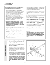
...of this manual. For your convenience and safety, assemble the home gym system with two 5/16Ó x 2 3/4Ó Bolts (11), two 5/16Ó Flat Washers (8), and two 5/16Ó Nylon Locknuts (3). Locate and open -end or closed-end wrenches, or a set of evenings. ¥ ... instructions: ¥ Due to the Stabilizer (5) with the help identifying the small parts used in assembly, use the PART IDENTIFICATION CHART located in the center of the Base (4). Insert six 5/16Ó x 2 1/2Ó Carriage Bolts (1) up through Friday, 6 a.m. Do not tighten the Nylon Locknuts yet. 5 1 51 51 ...
...of this manual. For your convenience and safety, assemble the home gym system with two 5/16Ó x 2 3/4Ó Bolts (11), two 5/16Ó Flat Washers (8), and two 5/16Ó Nylon Locknuts (3). Locate and open -end or closed-end wrenches, or a set of evenings. ¥ ... instructions: ¥ Due to the Stabilizer (5) with the help identifying the small parts used in assembly, use the PART IDENTIFICATION CHART located in the center of the Base (4). Insert six 5/16Ó x 2 1/2Ó Carriage Bolts (1) up through Friday, 6 a.m. Do not tighten the Nylon Locknuts yet. 5 1 51 51 ...

English Manual
Page 9
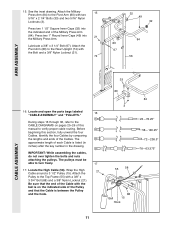
... 27 98 17 Holes must be a tight fit. Note: This will be able to the Base (4) with a 5/16Ó x 6Ó Bolt (60), two 1/2Ó x 3/4Ó Spacers (61), and a 5/16Ó Nylon Locknut (3). 9. Attach the upper ends of the Long Weight Guides (62) to the Stabilizer (5) with.... Slide the Press Frame into each welded spacer on the Leg Press Plate (95) with a 5/16Ó x 6Ó Bolt (60), two 1/2Ó x 3/4Ó Spacers (61), and a 5/16Ó Nylon Locknut (3). Locate and open the parts bag labeled ÒARM ASSEMBLY.Ó Be sure there is a Bushing (98...
... 27 98 17 Holes must be a tight fit. Note: This will be able to the Base (4) with a 5/16Ó x 6Ó Bolt (60), two 1/2Ó x 3/4Ó Spacers (61), and a 5/16Ó Nylon Locknut (3). 9. Attach the upper ends of the Long Weight Guides (62) to the Stabilizer (5) with.... Slide the Press Frame into each welded spacer on the Leg Press Plate (95) with a 5/16Ó x 6Ó Bolt (60), two 1/2Ó x 3/4Ó Spacers (61), and a 5/16Ó Nylon Locknut (3). Locate and open the parts bag labeled ÒARM ASSEMBLY.Ó Be sure there is a Bushing (98...
English Manual
Page 11
... inches) after the key number in the drawing. Locate the High Cable (58). See the inset drawing. Lubricate a 3/8Ó x 3 1/4Ó Bolt (67). Locate and open the parts bags labeled 16 ÒCABLE ASSEMBLYÓ and ÒPULLEYS.Ó During steps 16 through 36, refer to verify proper cable routing. The... the Top Frame (55) with the Bolt and a 3/8Ó Nylon Locknut (21). 74 32 49 32 84 80 67 56 ARM ASSEMBLY CABLE ASSEMBLY 33 16. The pulleys must be able to the Rear Upright (74) with a 3/8Ó x 3 3/4Ó Bolt (88) and a 3/8Ó Nylon Locknut (21). Press ...
... inches) after the key number in the drawing. Locate the High Cable (58). See the inset drawing. Lubricate a 3/8Ó x 3 1/4Ó Bolt (67). Locate and open the parts bags labeled 16 ÒCABLE ASSEMBLYÓ and ÒPULLEYS.Ó During steps 16 through 36, refer to verify proper cable routing. The... the Top Frame (55) with the Bolt and a 3/8Ó Nylon Locknut (21). 74 32 49 32 84 80 67 56 ARM ASSEMBLY CABLE ASSEMBLY 33 16. The pulleys must be able to the Rear Upright (74) with a 3/8Ó x 3 3/4Ó Bolt (88) and a 3/8Ó Nylon Locknut (21). Press ...

English Manual
Page 14
...; Spacer (7) to the Press Frame (17) with a 3/8Ó x 3 1/2Ó Bolt (16), a 3/8Ó Flat Washer (9), and a 3/8Ó Nylon Locknut (21). See the inset drawing. Route the Low Cable (23) around a 3 1/2Ó 26 Pulley (15). Attach the Pulley ... is turned to hold the Cable in place and that the Cable is routed around the Pulley as shown. 21 66 23 9 16 15 17 28. CABLE ASSEMBLY 25. Locate the Low Cable (23) and the bag labeled ÒLOW PULLEY.Ó Route the Low Cable under the 3 1/2Ó Low Pulley (76...
...; Spacer (7) to the Press Frame (17) with a 3/8Ó x 3 1/2Ó Bolt (16), a 3/8Ó Flat Washer (9), and a 3/8Ó Nylon Locknut (21). See the inset drawing. Route the Low Cable (23) around a 3 1/2Ó 26 Pulley (15). Attach the Pulley ... is turned to hold the Cable in place and that the Cable is routed around the Pulley as shown. 21 66 23 9 16 15 17 28. CABLE ASSEMBLY 25. Locate the Low Cable (23) and the bag labeled ÒLOW PULLEY.Ó Route the Low Cable under the 3 1/2Ó Low Pulley (76...

English Manual
Page 15
... a 1/4Ó Nylon Locknut (2) and a 1/4Ó Flat Washer (10). Attach the Military Press Cable to the Top Frame (55) with a 5/16Ó x 1 3/4Ó Bolt (24) and a 5/16Ó Nylon Locknut (3). 31. Attach the Pulley to the other Small ÒUÓ-Bracket (71) with a 1/4Ó Nylon Locknut (2) and a ... Cable (23) to hold the Cable in the inset drawing. Attach the Small ÒUÓ-Bracket (71) to the Long ÒUÓ-Bracket. Locate the Military Press Cable (72). Wrap the Military Press Cable (72) around a 3 1/2Ó Pulley (15). See the inset drawing. Attach the...
... a 1/4Ó Nylon Locknut (2) and a 1/4Ó Flat Washer (10). Attach the Military Press Cable to the Top Frame (55) with a 5/16Ó x 1 3/4Ó Bolt (24) and a 5/16Ó Nylon Locknut (3). 31. Attach the Pulley to the other Small ÒUÓ-Bracket (71) with a 1/4Ó Nylon Locknut (2) and a ... Cable (23) to hold the Cable in the inset drawing. Attach the Small ÒUÓ-Bracket (71) to the Long ÒUÓ-Bracket. Locate the Military Press Cable (72). Wrap the Military Press Cable (72) around a 3 1/2Ó Pulley (15). See the inset drawing. Attach the...

English Manual
Page 16
... that the Cable Trap is routed as shown. 33. Lay the Military Press Cable (72) over a 3 1/2Ó 34 Pulley (15). See the inset drawing. 16 99 72 9 Post 15 77 9 88 Large tabs must be in the Long ÒUÓ-Bracket (57) with the 3/8Ó x 5Ó Bolt (101). Wrap...(80) with a 3/8Ó x 2Ó Bolt (12) and a 3/8Ó Nylon Locknut (21). Attach the Pulley and a Cable Trap (66) to the upper hole in this location 56 The Pulley Covers (77) must be turned so that the Cable and Pulley move smoothly. Wrap the Military Press Cable (72) around a 3 1/2Ó Pulley...
... that the Cable Trap is routed as shown. 33. Lay the Military Press Cable (72) over a 3 1/2Ó 34 Pulley (15). See the inset drawing. 16 99 72 9 Post 15 77 9 88 Large tabs must be in the Long ÒUÓ-Bracket (57) with the 3/8Ó x 5Ó Bolt (101). Wrap...(80) with a 3/8Ó x 2Ó Bolt (12) and a 3/8Ó Nylon Locknut (21). Attach the Pulley and a Cable Trap (66) to the upper hole in this location 56 The Pulley Covers (77) must be turned so that the Cable and Pulley move smoothly. Wrap the Military Press Cable (72) around a 3 1/2Ó Pulley...

English Manual
Page 17
Be sure that the Cable and Pulley move smoothly and that the Cable is between the two Jam Nuts for cable adjustment.) Tighten a 5/16Ó Flat Washer (8) and a 5/16Ó Nylon Jam Nut (93) onto the Bolt. The ball on the indicated side of the Leg Press Cable to the Leg Press ...; Nylon Locknut (21). Attach the Press Bracket (94) to the Press Bracket (94) with a 3/8Ó x 3Ó Bolt (100) and 36 a 3/8Ó Nylon Jam Nut (99). Locate the Leg Press Cable (78). Wrap the Leg Press Cable (78) around a 3 1/2Ó Pulley (15). There must be threaded onto the end of the Cable...
Be sure that the Cable and Pulley move smoothly and that the Cable is between the two Jam Nuts for cable adjustment.) Tighten a 5/16Ó Flat Washer (8) and a 5/16Ó Nylon Jam Nut (93) onto the Bolt. The ball on the indicated side of the Leg Press Cable to the Leg Press ...; Nylon Locknut (21). Attach the Press Bracket (94) to the Press Bracket (94) with a 3/8Ó x 3Ó Bolt (100) and 36 a 3/8Ó Nylon Jam Nut (99). Locate the Leg Press Cable (78). Wrap the Leg Press Cable (78) around a 3 1/2Ó Pulley (15). There must be threaded onto the end of the Cable...

English Manual
Page 18
... Frame with a 1/4Ó Flat Washer (10) and a 1/4Ó x 2 1/2Ó Screw (43). 37 85 56 10 43 37 18 92 2 38 13 18 SEAT ASSEMBLY 39. Locate and open the parts bag labeled ÒSEAT ASSEMBLY.Ó Insert a 1/4Ó x 2 1/2Ó Carriage Bolt (92) through the indicated hole in a Seat Plate (37). Attach...
... Frame with a 1/4Ó Flat Washer (10) and a 1/4Ó x 2 1/2Ó Screw (43). 37 85 56 10 43 37 18 92 2 38 13 18 SEAT ASSEMBLY 39. Locate and open the parts bag labeled ÒSEAT ASSEMBLY.Ó Insert a 1/4Ó x 2 1/2Ó Carriage Bolt (92) through the indicated hole in a Seat Plate (37). Attach...
