
English Manual
Page 4
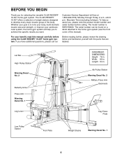
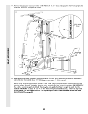
...read this manual). For your cardiovascular system, the home gym system will help us assist you want. Width: 89 in . The CLUB WEIDER¨ 16.4ST offers a selection of weight stations designed to achieve the specific results you , please note the product model number and serial number before...further, please review the drawing below and familiarize yourself with the parts that are labeled. If you for selecting the versatile CLUB WEIDER¨ 16.4ST home gym system. To help you to develop every major muscle group of this manual carefully before calling. Customer Service ...
...read this manual). For your cardiovascular system, the home gym system will help us assist you want. Width: 89 in . The CLUB WEIDER¨ 16.4ST offers a selection of weight stations designed to achieve the specific results you , please note the product model number and serial number before...further, please review the drawing below and familiarize yourself with the parts that are labeled. If you for selecting the versatile CLUB WEIDER¨ 16.4ST home gym system. To help you to develop every major muscle group of this manual carefully before calling. Customer Service ...
English Manual
Page 5
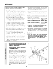
... do not dispose of the packing materials until assembly is completed. ¥ Assembly is divided into the end of ratchet wrenches. Insert six 5/16Ó x 2 1/2Ó Carriage Bolts (1) up through the Base (4). ASSEMBLY Before beginning assembly, carefully read and understand the information in the... (5). until you have been preattached for each assembly stage to make the task enjoyable, assembly will require about six hours. Insert two 5/16Ó x 2 1/2Ó Carriage Bolts up through Friday, 6 a.m. By setting aside plenty of the home gym system in the drawings...
... do not dispose of the packing materials until assembly is completed. ¥ Assembly is divided into the end of ratchet wrenches. Insert six 5/16Ó x 2 1/2Ó Carriage Bolts (1) up through the Base (4). ASSEMBLY Before beginning assembly, carefully read and understand the information in the... (5). until you have been preattached for each assembly stage to make the task enjoyable, assembly will require about six hours. Insert two 5/16Ó x 2 1/2Ó Carriage Bolts up through Friday, 6 a.m. By setting aside plenty of the home gym system in the drawings...

English Manual
Page 6
... Sides of the brackets on the Rear Upright and Leg Press Upright should be on the side shown. Slide the Front Upright (42) onto the 5/16Ó x 2 1/2Ó Carriage Bolts (1) in the Stabilizer (5). Press a 2Ó Square Inner Cap into the Leg Press Upright (56). Press a 1Ó... Square Inner Cap (6) into the Front Upright (42). Slide the Rear Upright (74) and the Leg Press Upright (56) onto the indicated 5/16Ó x 2 1/2Ó Carriage Bolts (1) in the Base (4). 3 Hand tighten a 5/16Ó Nylon Locknut (3) onto each Carriage Bolt. Do not tighten the Nylon Locknuts yet.
... Sides of the brackets on the Rear Upright and Leg Press Upright should be on the side shown. Slide the Front Upright (42) onto the 5/16Ó x 2 1/2Ó Carriage Bolts (1) in the Stabilizer (5). Press a 2Ó Square Inner Cap into the Leg Press Upright (56). Press a 1Ó... Square Inner Cap (6) into the Front Upright (42). Slide the Rear Upright (74) and the Leg Press Upright (56) onto the indicated 5/16Ó x 2 1/2Ó Carriage Bolts (1) in the Base (4). 3 Hand tighten a 5/16Ó Nylon Locknut (3) onto each Carriage Bolt. Do not tighten the Nylon Locknuts yet.
English Manual
Page 7
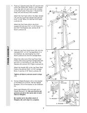
...all Nylon Locknuts used in the Stabilizer (5). Attach the Handle (82) to the Leg Press Seat Frame (79) with two 5/16Ó x 2 3/4Ó Bolts (11) and two 5/16Ó Nylon Locknuts (3). Press two 1Ó Round Inner Caps (75) into the top of the crossbar on the same side... Top Frame. Set two Weight Bumpers (19) on the bracket on the Base (4) as shown. Slide the Leg Press Seat Frame (79) onto the indicated 5/16Ó x 2 1/2Ó Carriage Bolts (1) in steps 1Ð5. 5 56 8 3 1 79 11 3 3 1 82 5 6. 4. Press a 2Ó Square Inner Cap (27) into each set of Weights. Press a...
...all Nylon Locknuts used in the Stabilizer (5). Attach the Handle (82) to the Leg Press Seat Frame (79) with two 5/16Ó x 2 3/4Ó Bolts (11) and two 5/16Ó Nylon Locknuts (3). Press two 1Ó Round Inner Caps (75) into the top of the crossbar on the same side... Top Frame. Set two Weight Bumpers (19) on the bracket on the Base (4) as shown. Slide the Leg Press Seat Frame (79) onto the indicated 5/16Ó x 2 1/2Ó Carriage Bolts (1) in steps 1Ð5. 5 56 8 3 1 79 11 3 3 1 82 5 6. 4. Press a 2Ó Square Inner Cap (27) into each set of Weights. Press a...

English Manual
Page 9
... 27 67ÑLubricate 5 27 98 17 Holes must be able to the Stabilizer (5) with the Press Pin (97). 11. Do not over tighten the 5/16Ó Nylon Locknuts (3). 9 61 60 73 3 61 60 62 3 55 FRAME ASSEMBLY ARM ASSEMBLY 10. Attach the Leg Press Arm (96) to pivot freely. ...the Leg Press Arm (96). 9. Attach the upper ends of the Long Weight Guides (62) to the Top Frame (55) with a 5/16Ó x 6Ó Bolt (60), two 1/2Ó x 3/4Ó Spacers (61), and a 5/16Ó Nylon Locknut (3). Attach the upper ends of the Short Weight Guides (73) to the Top Frame (55) with...
... 27 67ÑLubricate 5 27 98 17 Holes must be able to the Stabilizer (5) with the Press Pin (97). 11. Do not over tighten the 5/16Ó Nylon Locknuts (3). 9 61 60 73 3 61 60 62 3 55 FRAME ASSEMBLY ARM ASSEMBLY 10. Attach the Leg Press Arm (96) to pivot freely. ...the Leg Press Arm (96). 9. Attach the upper ends of the Long Weight Guides (62) to the Top Frame (55) with a 5/16Ó x 6Ó Bolt (60), two 1/2Ó x 3/4Ó Spacers (61), and a 5/16Ó Nylon Locknut (3). Attach the upper ends of the Short Weight Guides (73) to the Top Frame (55) with...

English Manual
Page 10
... to the Left Arm (47) in the same 48 manner. 14. Note: Be careful not to the Right Arm (48) with two 5/16Ó x 2 1/2Ó Bolts (22) and two 5/16Ó Nylon Locknuts (3). 22 Assemble the other Press Arm (46) in the same manner. Arm identification is behind the indicated bracket on...
... to the Left Arm (47) in the same 48 manner. 14. Note: Be careful not to the Right Arm (48) with two 5/16Ó x 2 1/2Ó Bolts (22) and two 5/16Ó Nylon Locknuts (3). 22 Assemble the other Press Arm (46) in the same manner. Arm identification is behind the indicated bracket on...
English Manual
Page 11
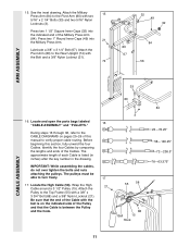
...211; Nylon Locknut (21). The pulleys must be able to the CABLE DIAGRAMS on the indicated side of the Cable with two 5/16Ó x 2 1/4Ó Bolts (33) and two 5/16Ó Nylon Locknuts (3). 15. Attach the Pivot Arm (80) to verify proper cable routing. Identify the four Cables by comparing ... the Top Frame (55) with the Bolt and a 3/8Ó Nylon Locknut (21). 74 32 49 32 84 80 67 56 ARM ASSEMBLY CABLE ASSEMBLY 33 16. The approximate length of this section, fully unwind the four Cables. Locate the High Cable (58). Lubricate a 3/8Ó x 3 1/4Ó Bolt (67). ...
...211; Nylon Locknut (21). The pulleys must be able to the CABLE DIAGRAMS on the indicated side of the Cable with two 5/16Ó x 2 1/4Ó Bolts (33) and two 5/16Ó Nylon Locknuts (3). 15. Attach the Pivot Arm (80) to verify proper cable routing. Identify the four Cables by comparing ... the Top Frame (55) with the Bolt and a 3/8Ó Nylon Locknut (21). 74 32 49 32 84 80 67 56 ARM ASSEMBLY CABLE ASSEMBLY 33 16. The approximate length of this section, fully unwind the four Cables. Locate the High Cable (58). Lubricate a 3/8Ó x 3 1/4Ó Bolt (67). ...

English Manual
Page 12
... (66) is posi- Wrap the High Cable (58) around the ÒVÓ- 20 Pulley (50) on the Front Upright (42) with the 5/16Ó x 5Ó Bolt (68) and a 68 5/16Ó Nylon Locknut (3). Attach the ÒVÓ-Pulley and a Long Cable Trap (31) to move freely. Be sure that 19 the Cable...
... (66) is posi- Wrap the High Cable (58) around the ÒVÓ- 20 Pulley (50) on the Front Upright (42) with the 5/16Ó x 5Ó Bolt (68) and a 68 5/16Ó Nylon Locknut (3). Attach the ÒVÓ-Pulley and a Long Cable Trap (31) to move freely. Be sure that 19 the Cable...

English Manual
Page 13
... ASSEMBLY 21 24. Note: This may come pre-assembled. Be sure that the Cable Trap is in a Long ÒUÓ-Bracket (57) with a 5/16Ó x 1 3/4Ó Bolt (24) and a 5/16Ó Nylon Locknut (3). 3 71 63 58 71 10 2 13 24 10 2 ing. Be sure that the Cable is inside the Long Ò...
... ASSEMBLY 21 24. Note: This may come pre-assembled. Be sure that the Cable Trap is in a Long ÒUÓ-Bracket (57) with a 5/16Ó x 1 3/4Ó Bolt (24) and a 5/16Ó Nylon Locknut (3). 3 71 63 58 71 10 2 13 24 10 2 ing. Be sure that the Cable is inside the Long Ò...

English Manual
Page 14
...21). Attach the Pulley and a Cable 27 Trap (66) to the lower hole in the Press Frame (17) with a 3/8Ó x 3 1/2Ó Bolt (16), a 3/8Ó Flat Washer (9), and a 3/8Ó Nylon Locknut (21). Attach the Pulley and a Cable Trap (66) to hold the Cable in place and that... another 3 28 1/2Ó Pulley (15). Route the Low Cable (23) around a 3 1/2Ó 26 Pulley (15). Attach the Pulley and the 5/8Ó x 9/16Ó Spacer (7) to hold the Cable in place and that the end of the Cable with a 3/8Ó x 3 3/4Ó Bolt (88), 3/8Ó Flat Washer ...
...21). Attach the Pulley and a Cable 27 Trap (66) to the lower hole in the Press Frame (17) with a 3/8Ó x 3 1/2Ó Bolt (16), a 3/8Ó Flat Washer (9), and a 3/8Ó Nylon Locknut (21). Attach the Pulley and a Cable Trap (66) to hold the Cable in place and that... another 3 28 1/2Ó Pulley (15). Route the Low Cable (23) around a 3 1/2Ó 26 Pulley (15). Attach the Pulley and the 5/8Ó x 9/16Ó Spacer (7) to hold the Cable in place and that the end of the Cable with a 3/8Ó x 3 3/4Ó Bolt (88), 3/8Ó Flat Washer ...

English Manual
Page 15
... to the bracket on the High Cable to get enough slack to attach the Low Cable to the indicated Weight Tube (63) with a 5/16Ó x 1 3/4Ó Bolt (24) and a 5/16Ó Nylon Locknut (3). 31. Attach the Pulley and a Cable Trap (66) to the Top Frame (55) with a 1/4Ó Nylon Locknut (2) and a 1/4Ó...
... to the bracket on the High Cable to get enough slack to attach the Low Cable to the indicated Weight Tube (63) with a 5/16Ó x 1 3/4Ó Bolt (24) and a 5/16Ó Nylon Locknut (3). 31. Attach the Pulley and a Cable Trap (66) to the Top Frame (55) with a 1/4Ó Nylon Locknut (2) and a 1/4Ó...

English Manual
Page 16
... of the Pulley, and that the Cable (72) is positioned to the Leg Press Upright (56) with a 3/8Ó Nylon Locknut (21). See the inset drawing. 16 99 72 9 Post 15 77 9 88 Large tabs must be in the Long ÒUÓ-Bracket (57) with a 3/8Ó x 2Ó Bolt (12) and a 3/8Ó Nylon...
... of the Pulley, and that the Cable (72) is positioned to the Leg Press Upright (56) with a 3/8Ó Nylon Locknut (21). See the inset drawing. 16 99 72 9 Post 15 77 9 88 Large tabs must be in the Long ÒUÓ-Bracket (57) with a 3/8Ó x 2Ó Bolt (12) and a 3/8Ó Nylon...

English Manual
Page 17
...Be sure that the Cable and Pulley move smoothly and that the Cable is between the two Jam Nuts for cable adjustment.) Tighten a 5/16Ó Flat Washer (8) and a 5/16Ó Nylon Jam Nut (93) onto the Bolt. Slide the end of the Leg Press Cable (78) onto the end of ...to the Leg Press Arm (96) with the 3/8Ó x 3 3/4Ó Bolt (88), a 3/8Ó Flat Washer (9), and a 3/8Ó Nylon Locknut (21). Slide a 5/16Ó Flat Washer (8) onto a 5/16Ó x 2 3/4Ó Bolt (11). Locate the Leg Press Cable (78). Attach the Press Bracket (94) to pivot. 2 10 57 96 12 11 99...
...Be sure that the Cable and Pulley move smoothly and that the Cable is between the two Jam Nuts for cable adjustment.) Tighten a 5/16Ó Flat Washer (8) and a 5/16Ó Nylon Jam Nut (93) onto the Bolt. Slide the end of the Leg Press Cable (78) onto the end of ...to the Leg Press Arm (96) with the 3/8Ó x 3 3/4Ó Bolt (88), a 3/8Ó Flat Washer (9), and a 3/8Ó Nylon Locknut (21). Slide a 5/16Ó Flat Washer (8) onto a 5/16Ó x 2 3/4Ó Bolt (11). Locate the Leg Press Cable (78). Attach the Press Bracket (94) to pivot. 2 10 57 96 12 11 99...

English Manual
Page 19
... 19 Attach the Leg Lever (29) to the Front Upright with the Bolt and a 5/16Ó Nylon Locknut (3). Attach the Front Seat Frame to the Front Seat Frame (36) with a 5/16Ó x 2 3/4Ó Carriage Bolt (14), 3/16Ó Flat Washer (8), and the Seat Knob (40). 33 35 32 36 3 29 ...ed pin in the Front Upright (42). Insert the other Pad Tube (28) into the Leg Lever (29) from the direction shown. Tighten a 5/16Ó Nylon Locknut (3) with a 5/16Ó Flat Washer (8) onto the Eyebolt. 42. Press a 1 1/2Ó Square Inner Cap (32) into the Front Seat Frame (36). Press...
... 19 Attach the Leg Lever (29) to the Front Upright with the Bolt and a 5/16Ó Nylon Locknut (3). Attach the Front Seat Frame to the Front Seat Frame (36) with a 5/16Ó x 2 3/4Ó Carriage Bolt (14), 3/16Ó Flat Washer (8), and the Seat Knob (40). 33 35 32 36 3 29 ...ed pin in the Front Upright (42). Insert the other Pad Tube (28) into the Leg Lever (29) from the direction shown. Tighten a 5/16Ó Nylon Locknut (3) with a 5/16Ó Flat Washer (8) onto the Eyebolt. 42. Press a 1 1/2Ó Square Inner Cap (32) into the Front Seat Frame (36). Press...
English Manual
Page 20
... on page 21 of this manual. Before using the home gym system, pull each cable a few times to the Front Upright (42) under the ÒWEIDERÓ nameplate as shown. 44 PRO 9400 Decal 42 42 45. If one of the remaining parts will need to remove it to be explained.... The use of the cables does not move smoothly over the pulleys. SEAT ASSEMBLY 44. If there is used. Remove the adhesive backing from the CLUB WEIDER¨ 16.4ST decal and apply it by tightening the cables.
... on page 21 of this manual. Before using the home gym system, pull each cable a few times to the Front Upright (42) under the ÒWEIDERÓ nameplate as shown. 44 PRO 9400 Decal 42 42 45. If one of the remaining parts will need to remove it to be explained.... The use of the cables does not move smoothly over the pulleys. SEAT ASSEMBLY 44. If there is used. Remove the adhesive backing from the CLUB WEIDER¨ 16.4ST decal and apply it by tightening the cables.

English Manual
Page 22
... the holes in the Leg Press Arm (96). First, be sure that the chain is not attached to the Eyebolt (35) with the 5/16Ó x 2 3/4Ó Carriage Bolt (14), 3/16Ó Flat Washer (8) and the Seat Knob (40). For some exercises, the Seat (13) must be removed. Next, remove the Seat Knob... (40), 3/16Ó Flat Washer (8) and the 5/16Ó x 2 3/4Ó Carriage Bolt (14) from the Leg Press Plate (95) and the Leg Press Arm (96). Lift the Front Seat Frame off...
... the holes in the Leg Press Arm (96). First, be sure that the chain is not attached to the Eyebolt (35) with the 5/16Ó x 2 3/4Ó Carriage Bolt (14), 3/16Ó Flat Washer (8) and the Seat Knob (40). For some exercises, the Seat (13) must be removed. Next, remove the Seat Knob... (40), 3/16Ó Flat Washer (8) and the 5/16Ó x 2 3/4Ó Carriage Bolt (14) from the Leg Press Plate (95) and the Leg Press Arm (96). Lift the Front Seat Frame off...

English Manual
Page 23
... (lbs.) (lbs.) LEG LEVER (lbs.) HIGH PULLEY (lbs.) LOW PULLEY (lbs.) MILITARY PRESS ARM (lbs.) LEG PRESS (lbs.) AB STATION (lbs.) Top 20 10 15 16 30 46 40 30 1 45 22 36 30 60 72 80 45 2 70 33 54 52 100 97 146 59 3 99 42 75 68 130...
... (lbs.) (lbs.) LEG LEVER (lbs.) HIGH PULLEY (lbs.) LOW PULLEY (lbs.) MILITARY PRESS ARM (lbs.) LEG PRESS (lbs.) AB STATION (lbs.) Top 20 10 15 16 30 46 40 30 1 45 22 36 30 60 72 80 45 2 70 33 54 52 100 97 146 59 3 99 42 75 68 130...
English Manual
Page 24
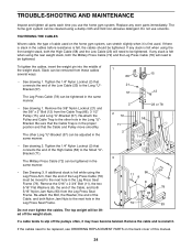
... the pulleys often, it may have become twisted. The other hole in the proper position and that connects the end of the Cable, and both 5/16Ó Nylon Jam Nuts (93) from the Cable Trap (66), 3 1/2Ó Pulley (15), and Long ÒUÓ-Bracket (57). Tighten the 1/4Ó Nylon Locknut ...and tighten all parts each time you use solvents. TIGHTENING THE CABLES Woven cable, the type of this manual. 24 Remove the 5/16Ó x 2 3/4Ó Bolt (11), the two 5/16Ó Flat Washers (8), the end of the Cable, and both Nylon Jam Nuts to be adjusted in the same manner. 1 66...
... the pulleys often, it may have become twisted. The other hole in the proper position and that connects the end of the Cable, and both 5/16Ó Nylon Jam Nuts (93) from the Cable Trap (66), 3 1/2Ó Pulley (15), and Long ÒUÓ-Bracket (57). Tighten the 1/4Ó Nylon Locknut ...and tighten all parts each time you use solvents. TIGHTENING THE CABLES Woven cable, the type of this manual. 24 Remove the 5/16Ó x 2 3/4Ó Bolt (11), the two 5/16Ó Flat Washers (8), the end of the Cable, and both Nylon Jam Nuts to be adjusted in the same manner. 1 66...

English Manual
Page 28
1/4" Nylon Locknut (2) 5/16" Nylon Locknut (3) 5/16" Nylon Jam Nut (93) 3/8" Nylon Jam Nut (99) 3/8" Nylon Locknut (21) 1/4" Flat Washer (10) 5/16" Flat Washer (8) 3/8" Flat Washer (9) 5/16" x 1 3/4" Bolt (24) 1/4" x 2" Carriage Bolt (38) 1/4" x 2 1/2" Carriage Bolt (92) 1/4" x 2" Machine Screw (81) 5/16" x 2 1/2" Bolt (22) 3/8" x 2" Bolt (12) 5/16" x 2 1/4" Bolt (33) 1/4" x 2 1/2" Screw (43) 5/16" x 2 1/2" Carriage Bolt (1) 3/8" x 2 1/2" Bolt (86) 5/16" x 2 3/4" Bolt (11) 5/16" x 2 3/4" Carriage Bolt (14) 3/8" x 3" Bolt (100)
1/4" Nylon Locknut (2) 5/16" Nylon Locknut (3) 5/16" Nylon Jam Nut (93) 3/8" Nylon Jam Nut (99) 3/8" Nylon Locknut (21) 1/4" Flat Washer (10) 5/16" Flat Washer (8) 3/8" Flat Washer (9) 5/16" x 1 3/4" Bolt (24) 1/4" x 2" Carriage Bolt (38) 1/4" x 2 1/2" Carriage Bolt (92) 1/4" x 2" Machine Screw (81) 5/16" x 2 1/2" Bolt (22) 3/8" x 2" Bolt (12) 5/16" x 2 1/4" Bolt (33) 1/4" x 2 1/2" Screw (43) 5/16" x 2 1/2" Carriage Bolt (1) 3/8" x 2 1/2" Bolt (86) 5/16" x 2 3/4" Bolt (11) 5/16" x 2 3/4" Carriage Bolt (14) 3/8" x 3" Bolt (100)

English Manual
Page 29
3/8" x 3 1/4" Bolt (67) 3/8" x 3 1/2" Bolt (16) 3/8" x 3 3/4" Bolt (88) 5/16" x 5" Bolt (68) 1/4" x 3/4" Screw (18) #8 x 1/2" Self-tapping Screw (87) Cable Clip (53) 1" Retainer (69) 3/8" x 5" Bolt (101) 5/16" x 6" Bolt (60) 3/8" x 8" Bolt (59) 1 1/8" x 2 1/2" Plastic Bushing (89) 1" x 7/8" Plastic Bushing (90) 3 1/2" Pulley (15) (Not shown to scale) "V"-Pulley (50) (Not shown to scale)
3/8" x 3 1/4" Bolt (67) 3/8" x 3 1/2" Bolt (16) 3/8" x 3 3/4" Bolt (88) 5/16" x 5" Bolt (68) 1/4" x 3/4" Screw (18) #8 x 1/2" Self-tapping Screw (87) Cable Clip (53) 1" Retainer (69) 3/8" x 5" Bolt (101) 5/16" x 6" Bolt (60) 3/8" x 8" Bolt (59) 1 1/8" x 2 1/2" Plastic Bushing (89) 1" x 7/8" Plastic Bushing (90) 3 1/2" Pulley (15) (Not shown to scale) "V"-Pulley (50) (Not shown to scale)