
User Manual
Page 2
...revenues or profits, loss of enjoyment or use or performance of the product or damages with all other warranty beyond that specifically set forth herein. This warranty extends only to be received by ICON. This warranty does not extend to any implied warranties of ...with respect to you . TABLE OF CONTENTS LIMITED WARRANTY IMPORTANT PRECAUTIONS BEFORE YOU BEGIN ASSEMBLY HOW TO USE THE HOME GYM SYSTEM TROUBLESHOOTING AND MAINTENANCE CABLE DIAGRAM ORDERING REPLACEMENT PARTS 2 3 4 5 15 18 19 Back Cover Note: A PART IDENTIFICATION CHART and a PART LIST/EXPLODED DRAWING are ...
...revenues or profits, loss of enjoyment or use or performance of the product or damages with all other warranty beyond that specifically set forth herein. This warranty extends only to be received by ICON. This warranty does not extend to any implied warranties of ...with respect to you . TABLE OF CONTENTS LIMITED WARRANTY IMPORTANT PRECAUTIONS BEFORE YOU BEGIN ASSEMBLY HOW TO USE THE HOME GYM SYSTEM TROUBLESHOOTING AND MAINTENANCE CABLE DIAGRAM ORDERING REPLACEMENT PARTS 2 3 4 5 15 18 19 Back Cover Note: A PART IDENTIFICATION CHART and a PART LIST/EXPLODED DRAWING are ...
User Manual
Page 5
..., check to see if it has been pre-attached. • As you assemble the WEIDER 8515, be needed. Press a 2" Square Inner Cap (27) into four stages: 1) frame assembly, 2) press and butterfly arm assembly, 3) cable and pulley assembly, and 4) seat and backrest assembly. Turn the Stabilizer (5) so that ...Locknut (3) onto each assembly stage to do not dispose of this manual. Note: Some small parts may have read the following tools: A socket set, a set of open that all parts are oriented as shown in the drawings. • Tighten all parts of the Base (4). Wet the handles on the...
..., check to see if it has been pre-attached. • As you assemble the WEIDER 8515, be needed. Press a 2" Square Inner Cap (27) into four stages: 1) frame assembly, 2) press and butterfly arm assembly, 3) cable and pulley assembly, and 4) seat and backrest assembly. Turn the Stabilizer (5) so that ...Locknut (3) onto each assembly stage to do not dispose of this manual. Note: Some small parts may have read the following tools: A socket set, a set of open that all parts are oriented as shown in the drawings. • Tighten all parts of the Base (4). Wet the handles on the...
User Manual
Page 15
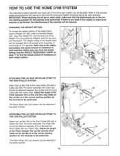
... the Lat Bar is performed, the effectiveness of the exercise will be attached in the correct starting position for the exercise to the Short Cable (58) with a Cable Clip (53). IMPORTANT: When attaching the lat bar or nylon strap, make sure that the attachments are in increments of 12.5 pounds. Note:...Bar and the Short Cable so the Lat Bar is touching the Weights, and turn the bent end downward. Insert the Weight Pin until the bent end of the weight stack, insert a Weight Pin (26) under the desired Weight (25). CHANGING THE WEIGHT SETTING To change the weight setting of the Weight ...
... the Lat Bar is performed, the effectiveness of the exercise will be attached in the correct starting position for the exercise to the Short Cable (58) with a Cable Clip (53). IMPORTANT: When attaching the lat bar or nylon strap, make sure that the attachments are in increments of 12.5 pounds. Note:...Bar and the Short Cable so the Lat Bar is touching the Weights, and turn the bent end downward. Insert the Weight Pin until the bent end of the weight stack, insert a Weight Pin (26) under the desired Weight (25). CHANGING THE WEIGHT SETTING To change the weight setting of the Weight ...
User Manual
Page 16
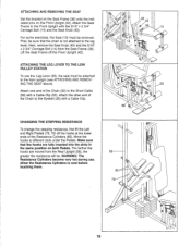
... and Right Pedals (78, 79) off the Front Upright (42). ATTACHING AND REMOVING THE SEAT Set the bracket on the Seat Frame (36) onto the indicated pins on both Pedals. The farther ...LEVER TO THE LOW PULLEY STATION To use . Attach the other end of the Chain (52) to the Short Cable (58) with a Cable Clip (53). Attach the Seat Frame to the Eyebolt (35) with the 5/16" x 2 3/4" Carriage Bolt... Seat (13) must be removed. Attach one end of the Chain to the Front Upright with a Cable Clip. Make sure that the chain is not attached to the front upright (see ATTACHING AND REMOVING THE...
... and Right Pedals (78, 79) off the Front Upright (42). ATTACHING AND REMOVING THE SEAT Set the bracket on the Seat Frame (36) onto the indicated pins on both Pedals. The farther ...LEVER TO THE LOW PULLEY STATION To use . Attach the other end of the Chain (52) to the Short Cable (58) with a Cable Clip (53). Attach the Seat Frame to the Eyebolt (35) with the 5/16" x 2 3/4" Carriage Bolt... Seat (13) must be removed. Attach one end of the Chain to the Front Upright with a Cable Clip. Make sure that the chain is not attached to the front upright (see ATTACHING AND REMOVING THE...


