
Uk Manual
Page 1
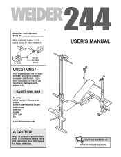
... if there are committed to providing complete customer satisfaction. Model No. Model Number Decal QUESTIONS? Save this equipment. As a manufacturer, we are missing or damaged parts, please call: 08457 089 009 Or write: ICON Health & Fitness, Ltd. WEEVBE38220 Serial No Write the serial number in this manual before using this manual for future reference. USER'S MANUAL Visit our website at www.iconeurope.com Unit 4 Revie...
... if there are committed to providing complete customer satisfaction. Model No. Model Number Decal QUESTIONS? Save this equipment. As a manufacturer, we are missing or damaged parts, please call: 08457 089 009 Or write: ICON Health & Fitness, Ltd. WEEVBE38220 Serial No Write the serial number in this manual before using this manual for future reference. USER'S MANUAL Visit our website at www.iconeurope.com Unit 4 Revie...
Uk Manual
Page 2
TABLE OF CONTENTS IMPORTANT PRECAUTIONS 3 BEFORE YOU BEGIN 4 PART IDENTIFICATION CHART 5 ASSEMBLY 6 ADJUSTMENTS 11 PART LIST 14 EXPLODED DRAWING 15 HOW TO ORDER REPLACEMENT PARTS Back Cover WEIDER is a registered trademark of ICON Health & Fitness, Inc. 2
TABLE OF CONTENTS IMPORTANT PRECAUTIONS 3 BEFORE YOU BEGIN 4 PART IDENTIFICATION CHART 5 ASSEMBLY 6 ADJUSTMENTS 11 PART LIST 14 EXPLODED DRAWING 15 HOW TO ORDER REPLACEMENT PARTS Back Cover WEIDER is a registered trademark of ICON Health & Fitness, Inc. 2
Uk Manual
Page 3
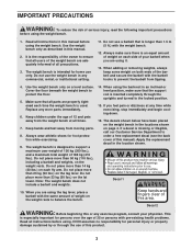
...-existing health problems. Read all instructions before using the weight bench. 1. This is the responsibility of the owner to prevent the barbell from moving parts. 8. When adding or removing weights, always keep some weight on the leg lever. Cover the floor beneath the weight bench to support a maximum user weight of 136 kg (300 lbs.), and a maximum total weight of 186 kg (410 lbs.). When using the backrest in the location shown...
...-existing health problems. Read all instructions before using the weight bench. 1. This is the responsibility of the owner to prevent the barbell from moving parts. 8. When adding or removing weights, always keep some weight on the leg lever. Cover the floor beneath the weight bench to support a maximum user weight of 136 kg (300 lbs.), and a maximum total weight of 186 kg (410 lbs.). When using the backrest in the location shown...
Uk Manual
Page 4
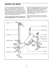
If you want. Lat Bar Cable Lat Tower Weight Carriage Leg Lever Warning Decal 2 Weight Tube Warning Decal 1 Weight Rests Barbell Hooks Upright Adjustment Knob Support Rod Fly Arm Weight Tube Backrest Seat 4 The versatile WEIDER® 244 weight bench is a shapely figure, dramatic muscle size and strength, or a healthier cardiovascular system, the WEIDER® 244 weight bench will help us assist you for selecting the WEIDER® 244 weight bench. For your benefit, read this manual.) Before reading further...
If you want. Lat Bar Cable Lat Tower Weight Carriage Leg Lever Warning Decal 2 Weight Tube Warning Decal 1 Weight Rests Barbell Hooks Upright Adjustment Knob Support Rod Fly Arm Weight Tube Backrest Seat 4 The versatile WEIDER® 244 weight bench is a shapely figure, dramatic muscle size and strength, or a healthier cardiovascular system, the WEIDER® 244 weight bench will help us assist you for selecting the WEIDER® 244 weight bench. For your benefit, read this manual.) Before reading further...

Uk Manual
Page 5
... CHART This chart is provided to help you cannot find a part in the parts bags, check to the key number of the part from the PART LIST on page 14. M10 x 137mm Bolt (36) M10 x 130mm Bolt (19) M10 x 63mm Bolt (32) M8 x 55mm Bolt (18) M10 x 55mm Bolt (42) M10 Nylon Locknut (33) M10 Washer (34) M8 Nylon Locknut (17, 58) M6 x 38mm Screw...
... CHART This chart is provided to help you cannot find a part in the parts bags, check to the key number of the part from the PART LIST on page 14. M10 x 137mm Bolt (36) M10 x 130mm Bolt (19) M10 x 63mm Bolt (32) M8 x 55mm Bolt (18) M10 x 55mm Bolt (42) M10 Nylon Locknut (33) M10 Washer (34) M8 Nylon Locknut (17, 58) M6 x 38mm Screw...
Uk Manual
Page 6
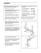
... you assemble them, unless instructed to the Front Leg (8) with two M8 x 50mm Carriage Bolts (49) and two M8 Nylon Locknuts (17). The following information and instructions: • Assembly requires two persons. • For help identifying small parts, use the PART IDENTIFICATION CHART on page 5. • Tighten all parts in the drawings. • Place all parts as you assemble the weight bench, make sure that the Uprights and...
... you assemble them, unless instructed to the Front Leg (8) with two M8 x 50mm Carriage Bolts (49) and two M8 Nylon Locknuts (17). The following information and instructions: • Assembly requires two persons. • For help identifying small parts, use the PART IDENTIFICATION CHART on page 5. • Tighten all parts in the drawings. • Place all parts as you assemble the weight bench, make sure that the Uprights and...
Uk Manual
Page 7
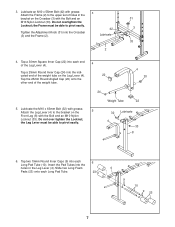
... to pivot easily. 42 3 Tighten the Adjustment Knob (31) into the Crossbar (3) and the Frame (2). Insert the Pad Tubes into each Long Pad Tube. 23 4 9 10 9 23 7 Lubricate an M10 x 55mm Bolt (42) with grease. 3 Attach the Frame (2) to the bracket on the Leg Lever (4). 22 Tap the 25mm... (10). Lubricate 33 2 4. Lubricate the M10 x 63mm Bolt (32) with the Bolt and an M10 Nylon Locknut (33). the Frame must be able to pivot easily. Tap a 30mm Square Inner Cap (22) into the indi- Attach the Leg Lever (4) to the upper set of holes in the Leg Lever (4). ...
... to pivot easily. 42 3 Tighten the Adjustment Knob (31) into the Crossbar (3) and the Frame (2). Insert the Pad Tubes into each Long Pad Tube. 23 4 9 10 9 23 7 Lubricate an M10 x 55mm Bolt (42) with grease. 3 Attach the Frame (2) to the bracket on the Leg Lever (4). 22 Tap the 25mm... (10). Lubricate 33 2 4. Lubricate the M10 x 63mm Bolt (32) with the Bolt and an M10 Nylon Locknut (33). the Frame must be able to pivot easily. Tap a 30mm Square Inner Cap (22) into the indi- Attach the Leg Lever (4) to the upper set of holes in the Leg Lever (4). ...
Uk Manual
Page 8
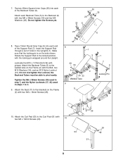
... pin wrapped around the Upright. Lubricate the M10 x 137mm Bolt (36) with the Bolt, two M10 Washers (34), and an M10 Nylon Locknut (33). Tighten the M6 x 38mm Screws (30) used in step 7, and the Nylon Locknuts (17, 33) used in the Uprights (1). Attach the Backrest Tubes (5) to the Backrest (6) with two M6 x 16mm Screws (29). 10 53 29 29 51 8 Rotate the Support...
... pin wrapped around the Upright. Lubricate the M10 x 137mm Bolt (36) with the Bolt, two M10 Washers (34), and an M10 Nylon Locknut (33). Tighten the M6 x 38mm Screws (30) used in step 7, and the Nylon Locknuts (17, 33) used in the Uprights (1). Attach the Backrest Tubes (5) to the Backrest (6) with two M6 x 16mm Screws (29). 10 53 29 29 51 8 Rotate the Support...
Uk Manual
Page 9
... in the indicated location. Press a 25mm Round Inner Cap (24) into the ends of the Lat Tower (40) with an M10 x 130mm Bolt (19) and a Butterfly Knob (13). Tap a Fly Arm Stop (15) onto the welded tube on the Pulley Covers are in the Upright. Repeat this step with an M8 Nylon Locknut (17). Attach the Pulley and a pair of Pulley Covers (43) inside of...
... in the indicated location. Press a 25mm Round Inner Cap (24) into the ends of the Lat Tower (40) with an M10 x 130mm Bolt (19) and a Butterfly Knob (13). Tap a Fly Arm Stop (15) onto the welded tube on the Pulley Covers are in the Upright. Repeat this step with an M8 Nylon Locknut (17). Attach the Pulley and a pair of Pulley Covers (43) inside of...
Uk Manual
Page 10
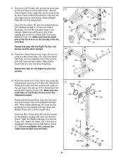
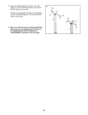
The use of all parts are properly tightened before you use the weight bench. Attach the Right Barbell Hook (54) to the left Upright (1) with an M8 Zinc Washer (57) and an M8 Zinc Nylon Locknut (58). 14. Attach the Left Barbell Hook (55) to the right Upright (1) with an M8 Zinc Washer (57) and an M8 Zinc Nylon Locknut (58). 14 58 57 1 15. Make sure that all remaining parts will be explained in ADJUSTMENTS, starting on the next page. 54 55 57 58 1 10
The use of all parts are properly tightened before you use the weight bench. Attach the Right Barbell Hook (54) to the left Upright (1) with an M8 Zinc Washer (57) and an M8 Zinc Nylon Locknut (58). 14. Attach the Left Barbell Hook (55) to the right Upright (1) with an M8 Zinc Washer (57) and an M8 Zinc Nylon Locknut (58). 14 58 57 1 15. Make sure that all remaining parts will be explained in ADJUSTMENTS, starting on the next page. 54 55 57 58 1 10
Uk Manual
Page 11
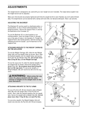
.... Next, slide the desired weights onto the weight tube. To use some weights, the Weight Adapter (56) will need to balance the bench. The steps below explain how the weight bench can be slid onto the Leg Lever. ADJUSTING THE BACKREST 1 The Backrest (6) can be used with the two Weight Clips (50). Make sure that all parts are properly tightened each Fly Arm. To use the Backrest (6) in a level...
.... Next, slide the desired weights onto the weight tube. To use some weights, the Weight Adapter (56) will need to balance the bench. The steps below explain how the weight bench can be slid onto the Leg Lever. ADJUSTING THE BACKREST 1 The Backrest (6) can be used with the two Weight Clips (50). Make sure that all parts are properly tightened each Fly Arm. To use the Backrest (6) in a level...
Uk Manual
Page 12
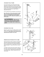
... weight bench. Place the Fly Arms in use. Secure the Lat Tower with a Cable Clip (41). ATTACHING THE LAT BAR Attach the Lat Bar (37) to perform if the Fly Arms (25, 59 [not shown]) are removed from the Fly Arm and Upright (1). REMOVING AND ATTACHING THE FLY ARMS Some exercises are easier to the Cable (39) with the Adjustment Knob (31). Note: Remove the Lat Bar from the Front Leg (8). Insert the Lat Tower into the Front Leg (8). Remove...
... weight bench. Place the Fly Arms in use. Secure the Lat Tower with a Cable Clip (41). ATTACHING THE LAT BAR Attach the Lat Bar (37) to perform if the Fly Arms (25, 59 [not shown]) are removed from the Fly Arm and Upright (1). REMOVING AND ATTACHING THE FLY ARMS Some exercises are easier to the Cable (39) with the Adjustment Knob (31). Note: Remove the Lat Bar from the Front Leg (8). Insert the Lat Tower into the Front Leg (8). Remove...
Uk Manual
Page 13
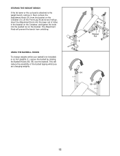
... change weights whilst your barbell (not included) is attached to the weight bench, remove it will reduce the possibility of holes in the bracket on the Crossbar, and tighten the knob into the welded nut on the Uprights (1), secure the barbell by rotating the Barbell Hooks (54, 55) over the barbell. Next, remove the Adjustment Knob (31) from unfolding. Insert the Adjustment Knob into the lower set...
... change weights whilst your barbell (not included) is attached to the weight bench, remove it will reduce the possibility of holes in the bracket on the Crossbar, and tighten the knob into the welded nut on the Uprights (1), secure the barbell by rotating the Barbell Hooks (54, 55) over the barbell. Next, remove the Adjustment Knob (31) from unfolding. Insert the Adjustment Knob into the lower set...
Uk Manual
Page 14
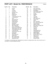
... 30mm Square Inner Cap Long Foam Pad 25mm Round Inner Cap Left Fly Arm M6 Washer Short Foam Pad Weight Stop M6 x 16mm Screw M6 x 38mm Screw Adjustment Knob Key No. Specifications are subject to change without notice. PART LIST-Model No. See the back cover for information on ordering replacement parts. 14 WEEVBE38220 R0903A Key No. Qty. 32 1 33 4 34 2 35 4 36 1 37 1 38 2 39 1 40 1 41...
... 30mm Square Inner Cap Long Foam Pad 25mm Round Inner Cap Left Fly Arm M6 Washer Short Foam Pad Weight Stop M6 x 16mm Screw M6 x 38mm Screw Adjustment Knob Key No. Specifications are subject to change without notice. PART LIST-Model No. See the back cover for information on ordering replacement parts. 14 WEEVBE38220 R0903A Key No. Qty. 32 1 33 4 34 2 35 4 36 1 37 1 38 2 39 1 40 1 41...
Uk Manual
Page 15
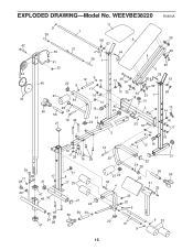
WEEVBE38220 R0903A 11 9 7 38 58 6 35 42 57 37 39 54 26 9 5 41 33 38 1 30 5 44 55 40 12 9 16 22 9 14 36 34 26 57 30 17 43 27 16 13 35 34 18 33 1 58 59 14 31 28 50 24 42 15 21 56 21 19 46 21 22 3 18 13 14 33 18 16 17 2 9 14 16 16 17 17 29 16 29 39 45 17 17 28 21 24 47 48 52 49 24 28 47 31 8 17 23 21 22 56 24 50 19 9 12 15 25 27 22 32 4 21 22 24 28 53 56 50 51 29 33 20 9 22 10 9 9 23 15 EXPLODED DRAWING-Model No.
WEEVBE38220 R0903A 11 9 7 38 58 6 35 42 57 37 39 54 26 9 5 41 33 38 1 30 5 44 55 40 12 9 16 22 9 14 36 34 26 57 30 17 43 27 16 13 35 34 18 33 1 58 59 14 31 28 50 24 42 15 21 56 21 19 46 21 22 3 18 13 14 33 18 16 17 2 9 14 16 16 17 17 29 16 29 39 45 17 17 28 21 24 47 48 52 49 24 28 47 31 8 17 23 21 22 56 24 50 19 9 12 15 25 27 22 32 4 21 22 24 28 53 56 50 51 29 33 20 9 22 10 9 9 23 15 EXPLODED DRAWING-Model No.
Uk Manual
Page 16
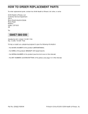
... MODEL NUMBER of the product (WEEVBE38220) • the NAME of the product (WEIDER® 244 weight bench) • the SERIAL NUMBER of the product (see the front cover of this manual) • the KEY NUMBER and DESCRIPTION of the part(s) (see page 14 in this manual) Part No. 200622 R0903A Printed in China © 2003 ICON Health & Fitness, Inc. office, or write: ICON Health & Fitness, Ltd. HOW TO ORDER REPLACEMENT PARTS To order replacement parts...
... MODEL NUMBER of the product (WEEVBE38220) • the NAME of the product (WEIDER® 244 weight bench) • the SERIAL NUMBER of the product (see the front cover of this manual) • the KEY NUMBER and DESCRIPTION of the part(s) (see page 14 in this manual) Part No. 200622 R0903A Printed in China © 2003 ICON Health & Fitness, Inc. office, or write: ICON Health & Fitness, Ltd. HOW TO ORDER REPLACEMENT PARTS To order replacement parts...


