
English Manual
Page 1
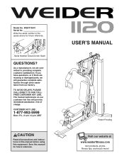
... guarantee complete satisfaction through direct assistance from our factory. WESY19541 Serial No. Write the serial number in this manual before using this manual for future reference. Serial Number Decal (Under Seat) QUESTIONS? Model No. MST CAUTION Read all precautions and instructions in the space above for future reference. If you have questions, or if there are missing or damaged parts, we are committed to...
... guarantee complete satisfaction through direct assistance from our factory. WESY19541 Serial No. Write the serial number in this manual before using this manual for future reference. Serial Number Decal (Under Seat) QUESTIONS? Model No. MST CAUTION Read all precautions and instructions in the space above for future reference. If you have questions, or if there are missing or damaged parts, we are committed to...
English Manual
Page 2
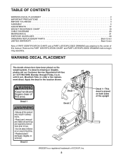
... PRECAUTIONS 3 BEFORE YOU BEGIN 4 ASSEMBLY 5 ADJUSTMENTS 17 WEIGHT RESISTANCE CHART 19 CABLE DIAGRAMS 20 MAINTENANCE 21 EXERCISE GUIDELINES 22 ORDERING REPLACEMENT PARTS Back Cover LIMITED WARRANTY Back Cover Note: A PART IDENTIFICATION CHART and a PART LIST/EXPLODED DRAWING are attached in the location shown. Remove the PART IDENTIFICATION CHART and PART LIST/EXPLODED DRAWING before beginning assembly. WARNING DECAL PLACEMENT The decals shown here have been placed on both sides of the upright Decal 2 WEIDER is a registered trademark of this...
... PRECAUTIONS 3 BEFORE YOU BEGIN 4 ASSEMBLY 5 ADJUSTMENTS 17 WEIGHT RESISTANCE CHART 19 CABLE DIAGRAMS 20 MAINTENANCE 21 EXERCISE GUIDELINES 22 ORDERING REPLACEMENT PARTS Back Cover LIMITED WARRANTY Back Cover Note: A PART IDENTIFICATION CHART and a PART LIST/EXPLODED DRAWING are attached in the location shown. Remove the PART IDENTIFICATION CHART and PART LIST/EXPLODED DRAWING before beginning assembly. WARNING DECAL PLACEMENT The decals shown here have been placed on both sides of the upright Decal 2 WEIDER is a registered trademark of this...
English Manual
Page 3
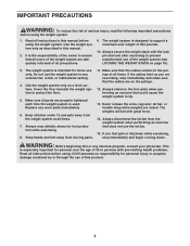
... times. 7. It is used. Make sure all users of the weight system are adequately informed of 300 pounds. 10. Never release the arms, leg lever, lat bar, or handle strap while weights are properly tightened each time the weight system is the responsibility of the owner to ensure that could cause the weight system to protect the floor. 5. If you are exercising, stop immediately and begin...
... times. 7. It is used. Make sure all users of the weight system are adequately informed of 300 pounds. 10. Never release the arms, leg lever, lat bar, or handle strap while weights are properly tightened each time the weight system is the responsibility of the owner to ensure that could cause the weight system to protect the floor. 5. If you are exercising, stop immediately and begin...
English Manual
Page 4
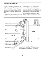
... model number is to tone your body, build dramatic muscle size and strength, or improve your benefit, read this manual, please call our Customer Service Department toll-free at 1-877-992-5999, Monday through Friday, 6 a.m. until 6 p.m. The serial number can be found on the seat; Depth: 65 in . Width: 38 in the manual. 4 Shroud Arm Backrest Seat Right Side Leg Lever Pin Leg Lever Low Pulley Station...
... model number is to tone your body, build dramatic muscle size and strength, or improve your benefit, read this manual, please call our Customer Service Department toll-free at 1-877-992-5999, Monday through Friday, 6 a.m. until 6 p.m. The serial number can be found on the seat; Depth: 65 in . Width: 38 in the manual. 4 Shroud Arm Backrest Seat Right Side Leg Lever Pin Leg Lever Low Pulley Station...
English Manual
Page 5
... assembly, make the task enjoyable, assembly will also need grease or petroleum jelly, a small amount of evenings. Set Aside Enough Time • You will go smoothly. Make sure that stage. Tightening Parts Tighten all parts as you assemble them, unless instructed to walk around the weight system as you assemble the weight system, all parts of its weight and size, the weight system should be assembled in individual bags. Note: Assembly...
... assembly, make the task enjoyable, assembly will also need grease or petroleum jelly, a small amount of evenings. Set Aside Enough Time • You will go smoothly. Make sure that stage. Tightening Parts Tighten all parts as you assemble them, unless instructed to walk around the weight system as you assemble the weight system, all parts of its weight and size, the weight system should be assembled in individual bags. Note: Assembly...
English Manual
Page 6
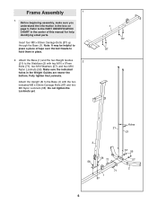
... page 5. Fully tighten the Locknuts. Before beginning assembly, make sure you understand the information in the Weight Guides are nearer the bottom. Attach the Base (1) and the two Weight Guides 2 (21) to the Base (1) with two M10 x 67mm Bolts (71), two M10 Washers (57), and two M10 Nylon Locknuts (56). Frame Assembly 1 1. Refer to the PART IDENTIFICATION CHART in place. 2. Attach the Upright (3) to...
... page 5. Fully tighten the Locknuts. Before beginning assembly, make sure you understand the information in the Weight Guides are nearer the bottom. Attach the Base (1) and the two Weight Guides 2 (21) to the Base (1) with two M10 x 67mm Bolts (71), two M10 Washers (57), and two M10 Nylon Locknuts (56). Frame Assembly 1 1. Refer to the PART IDENTIFICATION CHART in place. 2. Attach the Upright (3) to...
English Manual
Page 9
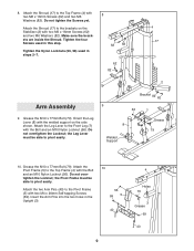
...Attach the two Arm Pins (40) to the Front Leg (7) with the Bolt and an M10 Nylon Locknut (56). Attach the Leg Lever to the Pivot Frame (5) with two M6 x 16mm Screws (62) and two M6 Washers (82). Grease the M10 x 77mm Bolt (79). Orient the Leg Lever (8) with the welded support ... 8 Welded Support Grease 79 10. Grease the M10 x 77mm Bolt (79). the Pivot Frame must be able to pivot easily. Tighten the four Screws used in the Upright (3). 10 56 69 5 40 9 4 Holes 79 3 Grease 69 40 Insert the Arm Pins into the two holes in steps 2-7. 8 62 82 62 82 4 17 2 Arm Assembly 9. Do not...
...Attach the two Arm Pins (40) to the Front Leg (7) with the Bolt and an M10 Nylon Locknut (56). Attach the Leg Lever to the Pivot Frame (5) with two M6 x 16mm Screws (62) and two M6 Washers (82). Grease the M10 x 77mm Bolt (79). Orient the Leg Lever (8) with the welded support ... 8 Welded Support Grease 79 10. Grease the M10 x 77mm Bolt (79). the Pivot Frame must be able to pivot easily. Tighten the four Screws used in the Upright (3). 10 56 69 5 40 9 4 Holes 79 3 Grease 69 40 Insert the Arm Pins into the two holes in steps 2-7. 8 62 82 62 82 4 17 2 Arm Assembly 9. Do not...

English Manual
Page 10
... Frame (5) with two M10 x 25mm Button Bolts (77) and two M10 Washers (57). Assemble the Right Arm (9) in the same manner. 9 66 Grease 39 56 10 42 11 57 77 57 Grease 9 67 5 44 57 Grease 57 56 10 Cable Assembly 13 13. Locate the Arm Cable (54). Attach the Right Arm (9) to the Left Arm (10) with the Bolt, two M10 Washers (57), the two...
... Frame (5) with two M10 x 25mm Button Bolts (77) and two M10 Washers (57). Assemble the Right Arm (9) in the same manner. 9 66 Grease 39 56 10 42 11 57 77 57 Grease 9 67 5 44 57 Grease 57 56 10 Cable Assembly 13 13. Locate the Arm Cable (54). Attach the Right Arm (9) to the Left Arm (10) with the Bolt, two M10 Washers (57), the two...
English Manual
Page 14
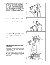
... the Cable Trap is removed from the cables. Route the High Cable (55) over a 90mm Pulley 28 (48) and down through the Top 27 Frame (4) and over a 90mm Thin Pulley (47). Tighten the High Cable (55) into the Weight Tube (24) until all the way onto the High Cable (55). Attach the Pulley, a Cable Trap... (51), and two Half Finger Guards (43) at the upper hole in the "U"-bracket (45) with the M10 x 67mm Bolt (71) used in step 25,...
... the Cable Trap is removed from the cables. Route the High Cable (55) over a 90mm Pulley 28 (48) and down through the Top 27 Frame (4) and over a 90mm Thin Pulley (47). Tighten the High Cable (55) into the Weight Tube (24) until all the way onto the High Cable (55). Attach the Pulley, a Cable Trap... (51), and two Half Finger Guards (43) at the upper hole in the "U"-bracket (45) with the M10 x 67mm Bolt (71) used in step 25,...
English Manual
Page 16
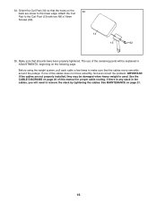
... ADJUSTMENTS, beginning on page 21. 16 Orient the Curl Pad (14) so that all parts have been properly tightened. The use of this manual for proper cable routing. 34. Before using the weight system, pull each cable a few times to the lower edge. IMPORTANT: If the cables are closer to make sure that the cables move smoothly, find and correct the problem. If there is used. Attach...
... ADJUSTMENTS, beginning on page 21. 16 Orient the Curl Pad (14) so that all parts have been properly tightened. The use of this manual for proper cable routing. 34. Before using the weight system, pull each cable a few times to the lower edge. IMPORTANT: If the cables are closer to make sure that the cables move smoothly, find and correct the problem. If there is used. Attach...
English Manual
Page 17
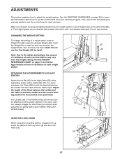
... WEIGHT SETTING To change the setting of resistance at either pulley stations in the correct starting position for each weight station. 25 22 26 ATTACHING THE ACCESSORIES TO A PULLEY STATION Attach the Lat Bar (35) to find the approximate amount of a weight stack, insert a Weight Pin (26) under the desired Weight (22). Insert the Weight Pin so that the Lat Bar is used. Use the WEIGHT RESISTANCE CHART on page 22 for important information about how to adjust...
... WEIGHT SETTING To change the setting of resistance at either pulley stations in the correct starting position for each weight station. 25 22 26 ATTACHING THE ACCESSORIES TO A PULLEY STATION Attach the Lat Bar (35) to find the approximate amount of a weight stack, insert a Weight Pin (26) under the desired Weight (22). Insert the Weight Pin so that the Lat Bar is used. Use the WEIGHT RESISTANCE CHART on page 22 for important information about how to adjust...
English Manual
Page 18
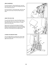
...) into the Front Leg (7) when performing an exercise that does not require the Curl Pad. To use the Arms (9, 10) as press arms, insert the Arm Pins (40) into the holes in the Pivot Frame (5) and Arms. USING THE CURL PAD To use the Arms (9, 10) as butterfly arms, insert the Arm Pins (40) into the holes in place with the Curl Knob (61). Store the...
...) into the Front Leg (7) when performing an exercise that does not require the Curl Pad. To use the Arms (9, 10) as press arms, insert the Arm Pins (40) into the holes in the Pivot Frame (5) and Arms. USING THE CURL PAD To use the Arms (9, 10) as butterfly arms, insert the Arm Pins (40) into the holes in place with the Curl Knob (61). Store the...
English Manual
Page 19
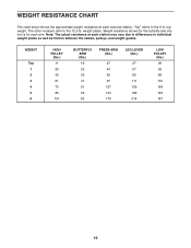
... for each arm. Note: The actual resistance at each exercise station. "Top" refers to differences in individual weight plates as well as friction between the cables, pulleys, and weight guides. The other numbers refer to the 12.5 lb. weight plates. WEIGHT Top 1 2 3 4 5 6 HIGH PULLEY (lbs.) 11 26 42 61 70 86 101 BUTTERFLY ARM (lbs.) 16 22 30 41 51 63 82 PRESS ARM (lbs...
... for each arm. Note: The actual resistance at each exercise station. "Top" refers to differences in individual weight plates as well as friction between the cables, pulleys, and weight guides. The other numbers refer to the 12.5 lb. weight plates. WEIGHT Top 1 2 3 4 5 6 HIGH PULLEY (lbs.) 11 26 42 61 70 86 101 BUTTERFLY ARM (lbs.) 16 22 30 41 51 63 82 PRESS ARM (lbs...
English Manual
Page 20
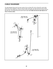
... the cables. Make sure that the cables, cable traps, and finger guards have not been correctly routed, the weight system will not function properly and damage may occur. High Cable (55) Length: 114 inches 4 5 3 2 1 4 2 5 Arm Cable (54) 1 Length: 89 inches 3 6 6 4 3 Low Cable (53) Length: 128 inches 5 2 1 20 CABLE DIAGRAMS The cable diagrams below show the correct route for each cable. If the cables have been assembled correctly...
... the cables. Make sure that the cables, cable traps, and finger guards have not been correctly routed, the weight system will not function properly and damage may occur. High Cable (55) Length: 114 inches 4 5 3 2 1 4 2 5 Arm Cable (54) 1 Length: 89 inches 3 6 6 4 3 Low Cable (53) Length: 128 inches 5 2 1 20 CABLE DIAGRAMS The cable diagrams below show the correct route for each cable. If the cables have been assembled correctly...
English Manual
Page 21
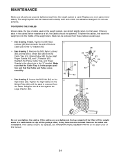
... the cables. Reattach the Pulley, Cable Trap, and Finger Guards to slip off the weight stack. If the cables need to the "U"-bracket (45). • See drawing 1. If a cable tends to the other hole in the proper position and that connects the end of cable used on the weight system, can be replaced, see ORDERING REPLACEMENT PARTS on the 2 High Cable (55). Remove the cable and re-install it...
... the cables. Reattach the Pulley, Cable Trap, and Finger Guards to slip off the weight stack. If the cables need to the "U"-bracket (45). • See drawing 1. If a cable tends to the other hole in the proper position and that connects the end of cable used on the weight system, can be replaced, see ORDERING REPLACEMENT PARTS on the 2 High Cable (55). Remove the cable and re-install it...
English Manual
Page 22
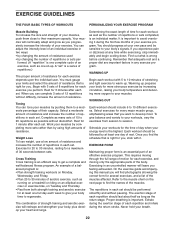
... workout should last about half as long as the number of repetitions or sets completed, is right for several exercises, and a list of your heart and lungs. Once you will reshape and strengthen your body, plus develop your exercise program. EXERCISE FORM Maintaining proper form is an efficient way to 10 different exercises. This requires moving only the appropriate parts of the muscles. On the exercise guide...
... workout should last about half as long as the number of repetitions or sets completed, is right for several exercises, and a list of your heart and lungs. Once you will reshape and strengthen your body, plus develop your exercise program. EXERCISE FORM Maintaining proper form is an efficient way to 10 different exercises. This requires moving only the appropriate parts of the muscles. On the exercise guide...
English Manual
Page 23
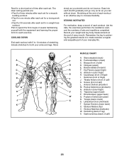
... your weight and key body measurements at the end of each workout is to make exercise a regular and enjoyable part of your arms and legs. Remember, the key to ...List the date, the exercises performed, the resistance used, and the numbers of leg) X. Quadriceps (front of thigh) I J K L M N O P Q R S T U V W X MUSCLE CHART A. Anterior Deltoid (shoulder) M. Rest for a short period of time after each set for both your everyday life. STAYING MOTIVATED For motivation, keep a record of calf) 23 A B C D E F G H I . Pectoralis Major (chest) C. Gastrocnemius (back of each workout...
... your weight and key body measurements at the end of each workout is to make exercise a regular and enjoyable part of your arms and legs. Remember, the key to ...List the date, the exercises performed, the resistance used, and the numbers of leg) X. Quadriceps (front of thigh) I J K L M N O P Q R S T U V W X MUSCLE CHART A. Anterior Deltoid (shoulder) M. Rest for a short period of time after each set for both your everyday life. STAYING MOTIVATED For motivation, keep a record of calf) 23 A B C D E F G H I . Pectoralis Major (chest) C. Gastrocnemius (back of each workout...

English Manual
Page 24
... key number of the part, from the PART LIST in assembly. PART IDENTIFICATION CHART Refer to the drawings below to see if it has been pre-attached. The number in parentheses by each drawing is not in the parts bag, check to identify small parts used in the center of this manual. M6 Locknut (78) M12 Nut (84) M10 Nylon Locknut (56) M10 x 25mm Button Bolt...
... key number of the part, from the PART LIST in assembly. PART IDENTIFICATION CHART Refer to the drawings below to see if it has been pre-attached. The number in parentheses by each drawing is not in the parts bag, check to identify small parts used in the center of this manual. M6 Locknut (78) M12 Nut (84) M10 Nylon Locknut (56) M10 x 25mm Button Bolt...
English Manual
Page 25
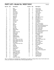
... Bolt 80 1 Handle Strap 81 3 M10 x 46mm Bolt 82 10 M6 Washer 83 1 Chain 84 1 M12 Nut 85 1 Large Washer 86 1 M10 x 70mm Bolt 87 4 M8 x 63mm Carriage Bolt 88 1 Lock 89 1 Lock Pin # 1 User's Manual # 1 Exercise Guide # 2 Grease Packet # 1 Allen Wrench Note: "#" indicates a non-illustrated part. Qty. See the back cover of the user's manual for information about ordering replacement parts. Description Key No. Qty. PART LIST-Model No. WESY19541 R0904A Key...
... Bolt 80 1 Handle Strap 81 3 M10 x 46mm Bolt 82 10 M6 Washer 83 1 Chain 84 1 M12 Nut 85 1 Large Washer 86 1 M10 x 70mm Bolt 87 4 M8 x 63mm Carriage Bolt 88 1 Lock 89 1 Lock Pin # 1 User's Manual # 1 Exercise Guide # 2 Grease Packet # 1 Allen Wrench Note: "#" indicates a non-illustrated part. Qty. See the back cover of the user's manual for information about ordering replacement parts. Description Key No. Qty. PART LIST-Model No. WESY19541 R0904A Key...
English Manual
Page 28
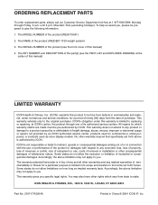
... damage, abuse, misuse, improper or abnormal usage or repairs not provided by ICON. The KEY NUMBER and DESCRIPTION of the part(s) (see the front cover of enjoyment or use and service conditions, for a particular purpose is limited in workmanship and material, under this manual) 4. Mountain Time (excluding holidays). products used as store display models. The warranty extended hereunder is in lieu of incidental or...
... damage, abuse, misuse, improper or abnormal usage or repairs not provided by ICON. The KEY NUMBER and DESCRIPTION of the part(s) (see the front cover of enjoyment or use and service conditions, for a particular purpose is limited in workmanship and material, under this manual) 4. Mountain Time (excluding holidays). products used as store display models. The warranty extended hereunder is in lieu of incidental or...


