
2006 VAIO Accessories Guide
Page 2
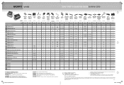
... their respective owners. Accessible capacity may not communicate with each other trademarks are not universally compatible. 3 Interoperability among Bluetooth® devices varies. 4 Shown with an i.LINK connector may vary. 2 DVD media/formats are trademarks of Sony used only to hard drive capacity. Sony® VAIO® Accessories Guide Summer 2006 FE AX AR FS FJ Memory Card Adapter Wireless Keyboard & Mouse Privacy Filter Mouse Talk™ VoIP Phone USB Optical Mouse Model # VGP-MCA10...
... their respective owners. Accessible capacity may not communicate with each other trademarks are not universally compatible. 3 Interoperability among Bluetooth® devices varies. 4 Shown with an i.LINK connector may vary. 2 DVD media/formats are trademarks of Sony used only to hard drive capacity. Sony® VAIO® Accessories Guide Summer 2006 FE AX AR FS FJ Memory Card Adapter Wireless Keyboard & Mouse Privacy Filter Mouse Talk™ VoIP Phone USB Optical Mouse Model # VGP-MCA10...
VAIO Accessories Guide Spring 2006
Page 1
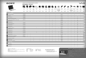
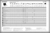
...-enabled control for 200 audio CDs and/or movie DVDs • Operated through Microsoft® Windows® XP Media Center Edition 2005 • Automatic download of title, jacket cover and other information (Internet connection required) • Automatic and sequential copying of 200 audio CDs to the PC hard drive • Multi episode TV program recording to DVD® software, i.LINK®4 connector cable and upright stand. DDRW3 Max. Read DVD-ROM...
...-enabled control for 200 audio CDs and/or movie DVDs • Operated through Microsoft® Windows® XP Media Center Edition 2005 • Automatic download of title, jacket cover and other information (Internet connection required) • Automatic and sequential copying of 200 audio CDs to the PC hard drive • Multi episode TV program recording to DVD® software, i.LINK®4 connector cable and upright stand. DDRW3 Max. Read DVD-ROM...
VAIO Accessories Guide Spring 2006
Page 2
...-D, S Video out, Video out (NTSC/PAL, pin jack), audio in connectors (pin jack), audio out connectors (pin jack) optical audio out and DC in . VGP-PRFJ1: 3 USB 2.0, RJ-45 Ethernet, Printer, VGA out and DC in . Sony, VAIO, Click to DVD, Digital Living System, i.Link, and RoomLink are registered trademarks of Sony. Microsoft and Windows are trademarks of Microsoft Corporation. VAIO® ACCESSORIES GUIDE SPRING 2006 SERIES: Model # Wireless USB Optical USB Optical Wireless Bluetooth® Keyboard & Mobile Mouse Presentation Wireless Mouse Mouse Mouse Mouse3...
...-D, S Video out, Video out (NTSC/PAL, pin jack), audio in connectors (pin jack), audio out connectors (pin jack) optical audio out and DC in . VGP-PRFJ1: 3 USB 2.0, RJ-45 Ethernet, Printer, VGA out and DC in . Sony, VAIO, Click to DVD, Digital Living System, i.Link, and RoomLink are registered trademarks of Sony. Microsoft and Windows are trademarks of Microsoft Corporation. VAIO® ACCESSORIES GUIDE SPRING 2006 SERIES: Model # Wireless USB Optical USB Optical Wireless Bluetooth® Keyboard & Mobile Mouse Presentation Wireless Mouse Mouse Mouse Mouse3...
VGC-RBxx Series Hard Disk Drive Replacement Instructions
Page 1
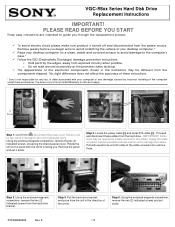
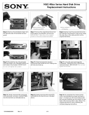
... set it aside. PLEASE READ BEFORE YOU START These easy instructions are intended to the computer's case. * ü Follow the ESD (Electrostatic Discharge) damage prevention instructions: o Hold parts by incorrect handling of the arrow. Remove jewelry before you . The terms of the cable connectors to apply. 2 Screws [1] [2] Step 1. Using the enclosed magnetic screwdriver, remove the two (2) indicated screws, loosening the chassis panel cover. Locate the power cable...
... set it aside. PLEASE READ BEFORE YOU START These easy instructions are intended to the computer's case. * ü Follow the ESD (Electrostatic Discharge) damage prevention instructions: o Hold parts by incorrect handling of the arrow. Remove jewelry before you . The terms of the cable connectors to apply. 2 Screws [1] [2] Step 1. Using the enclosed magnetic screwdriver, remove the two (2) indicated screws, loosening the chassis panel cover. Locate the power cable...
VGC-RBxx Series Hard Disk Drive Replacement Instructions
Page 2
... removed screws . E 2/2 Notice position of the bracket and HDD Step 7. IMPORTANT! Gently reconnect the previously removed power connector marked P8 [1] into the hard drive as the original hard drive. Connect your PC and continue with the recovery following the included shipping instructions. Notice position of the pins Step 8. Step 14. Pull out the original hard drive from the opposite side of the arrow. Step 9. VGC-RBxx Series Hard Disk Drive Replacement Instructions...
... removed screws . E 2/2 Notice position of the bracket and HDD Step 7. IMPORTANT! Gently reconnect the previously removed power connector marked P8 [1] into the hard drive as the original hard drive. Connect your PC and continue with the recovery following the included shipping instructions. Notice position of the pins Step 8. Step 14. Pull out the original hard drive from the opposite side of the arrow. Step 9. VGC-RBxx Series Hard Disk Drive Replacement Instructions...
VGC-RBxx Series Optical Disk Drive Lower Replacement Instructions
Page 1
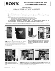
...! Using the enclosed magnetic screwdriver, remove the t w o (2) indicated screws, loosening the chassis panel cover. Step 4. Pull two (2) clips at the bottom of the computer under these instructions. * Sony is not responsible for any loss of data associated with your computer or any damage caused by incorrect handling of unit. VGC-RBxx Series Optical Disk Drive Lower Replacement Instructions IMPORTANT! PLEASE READ BEFORE YOU START These easy instructions...
...! Using the enclosed magnetic screwdriver, remove the t w o (2) indicated screws, loosening the chassis panel cover. Step 4. Pull two (2) clips at the bottom of the computer under these instructions. * Sony is not responsible for any loss of data associated with your computer or any damage caused by incorrect handling of unit. VGC-RBxx Series Optical Disk Drive Lower Replacement Instructions IMPORTANT! PLEASE READ BEFORE YOU START These easy instructions...
VGC-RBxx Series Optical Disk Drive Upper Replacement Instructions
Page 1
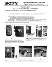
... of your desktop computer.* ü Place your desktop computer on the inside of the front of the unit : Step [2B], as this example: the upper optical drive.) NOTE! Remove the power connector [1] and the IDE data cable [ 2] from the components shipped. VGC-RBxx Series Optical Disk Drive Upper Replacement Instructions IMPORTANT! Remove jewelry before you are intended to the computer's case.* ü Follow the ESD (Electrostatic Discharge) damage prevention instructions: o Hold parts by...
... of your desktop computer.* ü Place your desktop computer on the inside of the front of the unit : Step [2B], as this example: the upper optical drive.) NOTE! Remove the power connector [1] and the IDE data cable [ 2] from the components shipped. VGC-RBxx Series Optical Disk Drive Upper Replacement Instructions IMPORTANT! Remove jewelry before you are intended to the computer's case.* ü Follow the ESD (Electrostatic Discharge) damage prevention instructions: o Hold parts by...
User Guide (primary user manual)
Page 4
... VAIO Support Central menu, click the Categories tab, then click the System Information folder. 3. Hard Disk Drive Recovery Your computer is equipped with the appropriate optical drive (a CD-RW, DVD-RW, or DVD±RW drive). For online information about using CD-R, single layer DVD+R, or single layer DVD-R media on your data with Click to locate your model's specifications sheet. You can create a VAIO Recovery Media Kit using the Sony software programs preinstalled on -screen instructions to DVD software...
... VAIO Support Central menu, click the Categories tab, then click the System Information folder. 3. Hard Disk Drive Recovery Your computer is equipped with the appropriate optical drive (a CD-RW, DVD-RW, or DVD±RW drive). For online information about using CD-R, single layer DVD+R, or single layer DVD-R media on your data with Click to locate your model's specifications sheet. You can create a VAIO Recovery Media Kit using the Sony software programs preinstalled on -screen instructions to DVD software...
User Guide (primary user manual)
Page 9
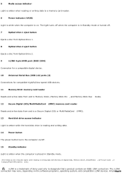
i.LINK is a trademark of Sony used only to a memory card reader. 6 Power indicator (VAIO) Light is white when the computer is on. The i.LINK connection may vary, depending on /off . 7 Optical drive 1 eject button Ejects a disc from Optical drive 1. 8 Optical drive 2 eject button Ejects a disc from Optical drive 2. 9 i.LINK 4-pin S400 port (IEEE 1394) Connection for a compatible digital device. 10 Universal Serial Bus (USB 2.0) ports (2) Connections for compatible high/full/low-speed USB devices. 11 Memory Stick® memory card reader Reads and writes data from and to...
i.LINK is a trademark of Sony used only to a memory card reader. 6 Power indicator (VAIO) Light is white when the computer is on. The i.LINK connection may vary, depending on /off . 7 Optical drive 1 eject button Ejects a disc from Optical drive 1. 8 Optical drive 2 eject button Ejects a disc from Optical drive 2. 9 i.LINK 4-pin S400 port (IEEE 1394) Connection for a compatible digital device. 10 Universal Serial Bus (USB 2.0) ports (2) Connections for compatible high/full/low-speed USB devices. 11 Memory Stick® memory card reader Reads and writes data from and to...
User Guide (primary user manual)
Page 12
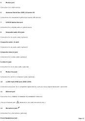
...low-speed USB devices. 7 S/PDIF Optical Out port Connection for a digital audio or optical device. 8 Composite audio R In jack2 Connection for a microphone (optional). S-video In jack2 Connection for an S-video cable (optional). 9 Modem line jack3 Connection for an RJ-11 telephone cable (optional). 10 i.LINK 6-pin S400 port (IEEE 1394) Connection and power for a compatible digital device, such as a Sony Digital Handycam® camcorder. 11 Ethernet port Connection for a 10BASE-T/100BASE-TX/1000BASE-T Ethernet. (The port marked with (Network) is for LAN connections only...
...low-speed USB devices. 7 S/PDIF Optical Out port Connection for a digital audio or optical device. 8 Composite audio R In jack2 Connection for a microphone (optional). S-video In jack2 Connection for an S-video cable (optional). 9 Modem line jack3 Connection for an RJ-11 telephone cable (optional). 10 i.LINK 6-pin S400 port (IEEE 1394) Connection and power for a compatible digital device, such as a Sony Digital Handycam® camcorder. 11 Ethernet port Connection for a 10BASE-T/100BASE-TX/1000BASE-T Ethernet. (The port marked with (Network) is for LAN connections only...

User Guide (primary user manual)
Page 30
If necessary, plug the display's cable into the appropriate monitor port. 2. To connect a display Install your computer's hardware configuration 1. Connecting a Display (Monitor) The location, availability, and type of an emergency. Plug the display's cable into the rear of the display. Page 30 See the specifications sheet for your computer on the Sony Online Support Web site at http://www.sony.com/pcsupport, for details about your equipment so that you can easily reach the power outlet in the event of the monitor port may vary, depending on the model purchased.
If necessary, plug the display's cable into the appropriate monitor port. 2. To connect a display Install your computer's hardware configuration 1. Connecting a Display (Monitor) The location, availability, and type of an emergency. Plug the display's cable into the rear of the display. Page 30 See the specifications sheet for your computer on the Sony Online Support Web site at http://www.sony.com/pcsupport, for details about your equipment so that you can easily reach the power outlet in the event of the monitor port may vary, depending on the model purchased.

User Guide (primary user manual)
Page 37
... mini stereo plugs (speaker system) to use your speaker system, as the connection setup may vary. Pink Microphone - Connect a Sub-woofer2, control module, or Center speaker (5.1 channel speaker system3) Black Rear - Green Front/Headphones - Connect rear speakers (5.1 channel speaker system). Connect the supplied speakers (2-channel), front speakers (5.1 channel speaker system), or optional headphones. See the information s upplied with your s peaker s ys tem for details on the back panel of your computer. Review the connection instructions provided with...
... mini stereo plugs (speaker system) to use your speaker system, as the connection setup may vary. Pink Microphone - Connect a Sub-woofer2, control module, or Center speaker (5.1 channel speaker system3) Black Rear - Green Front/Headphones - Connect rear speakers (5.1 channel speaker system). Connect the supplied speakers (2-channel), front speakers (5.1 channel speaker system), or optional headphones. See the information s upplied with your s peaker s ys tem for details on the back panel of your computer. Review the connection instructions provided with...
User Guide (primary user manual)
Page 44
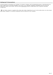
... shown in your home. Your computer's hardware configuration may require extra cables, adapters or connection equipment that are optional for details about your computer's hardware configuration. Your VAIO® computer is determined by the type of cable service connection available in this section. See the online Specifications sheet for your computer. Setting Up TV Connections The best method of connecting your computer, TV monitor or display, and TV programming access, is supplied with certain video cables. Page 44
... shown in your home. Your computer's hardware configuration may require extra cables, adapters or connection equipment that are optional for details about your computer's hardware configuration. Your VAIO® computer is determined by the type of cable service connection available in this section. See the online Specifications sheet for your computer. Setting Up TV Connections The best method of connecting your computer, TV monitor or display, and TV programming access, is supplied with certain video cables. Page 44

User Guide (primary user manual)
Page 71
... be different from the Windows® taskbar, click Control Panel, then click Performance and Maintenance. 2. Drive Mapping When a new hard disk drive is the default location to correct your drive mapping, create a VAIO Recovery Media Kit, or visit the Sony online support Web site for the first time, after you install an additional hard disk drive, the method of attaching connectors and cables may not reflect correct drive/icon associations. About Hard Disk Drive Installation Your computer may be changed.
... be different from the Windows® taskbar, click Control Panel, then click Performance and Maintenance. 2. Drive Mapping When a new hard disk drive is the default location to correct your drive mapping, create a VAIO Recovery Media Kit, or visit the Sony online support Web site for the first time, after you install an additional hard disk drive, the method of attaching connectors and cables may not reflect correct drive/icon associations. About Hard Disk Drive Installation Your computer may be changed.
User Guide (primary user manual)
Page 97
.... Remove the mouse ball cover on the mouse ball and inside the mouse mechanism. Turn the mouse upside down. 3. Using a wireless optical mouse If you are using a USB mouse, verify that the mouse is plugged securely into your mouse to close all open software programs and turn off the computer. The mouse driver(s) may cause the mouse to ensure proper mouse tracking. These devices may create interference, causing your hand. 5. If you are using a wireless optical mouse: Confirm that covers...
.... Remove the mouse ball cover on the mouse ball and inside the mouse mechanism. Turn the mouse upside down. 3. Using a wireless optical mouse If you are using a USB mouse, verify that the mouse is plugged securely into your mouse to close all open software programs and turn off the computer. The mouse driver(s) may cause the mouse to ensure proper mouse tracking. These devices may create interference, causing your hand. 5. If you are using a wireless optical mouse: Confirm that covers...

User Guide (primary user manual)
Page 99
... inside the mouse ball socket. 6. Using a standard ball mouse If you are using a USB mouse, verify that the mouse is plugged securely into the appropriate USB port. Save and close all open software programs and turn off the computer. The mouse driver(s) may be working properly. Do not place metal furniture near your wireless mouse. Using a piece of the mouse by turning clockwise the ring that covers the mouse ball. 4. Secure the cover...
... inside the mouse ball socket. 6. Using a standard ball mouse If you are using a USB mouse, verify that the mouse is plugged securely into the appropriate USB port. Save and close all open software programs and turn off the computer. The mouse driver(s) may be working properly. Do not place metal furniture near your wireless mouse. Using a piece of the mouse by turning clockwise the ring that covers the mouse ball. 4. Secure the cover...

User Guide (primary user manual)
Page 115
... appropriate port on -screen instructions to the user manual or guide supplied with Plug and Play capability. 5. Follow the on your computer's front, back or side panels1. Select a similar printer that may be required for proper installation. Check the printer manufacturer's Web site for the latest drivers for your operating system before proceeding with installation. Click Printers and Other Hardware, then click Add a Printer...
... appropriate port on -screen instructions to the user manual or guide supplied with Plug and Play capability. 5. Follow the on your computer's front, back or side panels1. Select a similar printer that may be required for proper installation. Check the printer manufacturer's Web site for the latest drivers for your operating system before proceeding with installation. Click Printers and Other Hardware, then click Add a Printer...
User Guide (primary user manual)
Page 116
... I install a printer? Connect your USB or IEEE 1284 printer to the appropriate port on -screen instructions to the user manual or guide supplied with your printer. 3. Select the appropriate port, usually LPT1 if using the parallel port, and then click Next. 6. Select a similar printer that may be required for proper installation. Check the printer manufacturer's Web site for the latest drivers for your operating...
... I install a printer? Connect your USB or IEEE 1284 printer to the appropriate port on -screen instructions to the user manual or guide supplied with your printer. 3. Select the appropriate port, usually LPT1 if using the parallel port, and then click Next. 6. Select a similar printer that may be required for proper installation. Check the printer manufacturer's Web site for the latest drivers for your operating...
User Guide (primary user manual)
Page 126
... to remove the RAID configuration. It lists detailed procedures for details about restoring individual software programs, software drivers, drive partition(s), or your hard copy guides and supplements, or by consulting your entire hard disk drive to the Sony online support Web site at http://www.sony.com/pcsupport. 3. Provides information about your Sony VAIO® computer. Click Start in the Windows® taskbar, click All Programs, then click VAIO Central. 2. Click VAIO User Guide. Specifications - The online specifications...
... to remove the RAID configuration. It lists detailed procedures for details about restoring individual software programs, software drivers, drive partition(s), or your hard copy guides and supplements, or by consulting your entire hard disk drive to the Sony online support Web site at http://www.sony.com/pcsupport. 3. Provides information about your Sony VAIO® computer. Click Start in the Windows® taskbar, click All Programs, then click VAIO Central. 2. Click VAIO User Guide. Specifications - The online specifications...
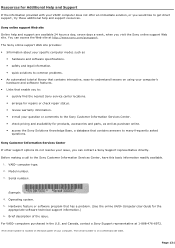
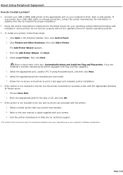
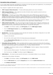
User Guide (primary user manual)
Page 131
... asked questions. T he s erial number is on the bac k panel of the issue. Resources for the appropriate software technical support information.) 6. Sony Customer Information Services Center If other support options do not resolve your c omputer. Before making a call to the Sony Customer Information Services Center, have this basic information readily available. 1. Model number. 3. You can contact a Sony Support representative directly. VAIO® computer type. 2. Serial number1. Example: 4. Operating system. 5. Brief description of your...
... asked questions. T he s erial number is on the bac k panel of the issue. Resources for the appropriate software technical support information.) 6. Sony Customer Information Services Center If other support options do not resolve your c omputer. Before making a call to the Sony Customer Information Services Center, have this basic information readily available. 1. Model number. 3. You can contact a Sony Support representative directly. VAIO® computer type. 2. Serial number1. Example: 4. Operating system. 5. Brief description of your...


