
Installation Manual
Page 4
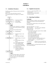
...". For the customers in als klein chemisch afval (KCA). Providing protective earth When this product is installed in a rack, please make sure that the outlet is within the specified limit of the Operation Manual. 6. When performing the installation, keep the following space away from walls in order to the specifications of this product is supplied power from an...
...". For the customers in als klein chemisch afval (KCA). Providing protective earth When this product is installed in a rack, please make sure that the outlet is within the specified limit of the Operation Manual. 6. When performing the installation, keep the following space away from walls in order to the specifications of this product is supplied power from an...
Installation Manual
Page 5
... Space 1-3 (E) 1-6. Removing/Reattaching Lower Control Panel Unit 1-18 (E) 1-13. Settings and Adjustment when External Equipment is Connected 1-21 (E) 1-15-1. Settings for Time Code 1-21 (E) 1-15-2. System Phase Alignment 1-22 (E) 1-16. Power Cord 1-2 (E) 1-5. Operation Mode Settings 1-17 (E) 1-11-1. VTR Constant Values Settings of this manual 2 (E) Related manuals 2 (E) 1. Taking Out the Cassette in Board 1-22 (E) 1-17. Installation Procedure 1-1 (E) 1-2. Voltage and Power Requirements 1-2 (E) 1-4-2. Switching Search Dial Mode 1-19 (E) 1-14. Power Supply...
... Space 1-3 (E) 1-6. Removing/Reattaching Lower Control Panel Unit 1-18 (E) 1-13. Settings and Adjustment when External Equipment is Connected 1-21 (E) 1-15-1. Settings for Time Code 1-21 (E) 1-15-2. System Phase Alignment 1-22 (E) 1-16. Power Cord 1-2 (E) 1-5. Operation Mode Settings 1-17 (E) 1-11-1. VTR Constant Values Settings of this manual 2 (E) Related manuals 2 (E) 1. Taking Out the Cassette in Board 1-22 (E) 1-17. Installation Procedure 1-1 (E) 1-2. Voltage and Power Requirements 1-2 (E) 1-4-2. Switching Search Dial Mode 1-19 (E) 1-14. Power Supply...
Installation Manual
Page 6
... Digital Videocassette Recorder HDW-1800/D1800. Maintenance Manual (Available on request) This "Semiconductor Pin Assignments" CD-ROM allows you to install (environment, connection information, initial setting, etc.) and the setting check sheet. Related manuals Besides this "installation manual", the following manuals are available for this unit. . Operation Manual (Supplied with the CD-ROM. "Semiconductor Pin Assignments" CD-ROM (Available on request) Volume-1 : Service Instruction Volume-2 : Parts...
... Digital Videocassette Recorder HDW-1800/D1800. Maintenance Manual (Available on request) This "Semiconductor Pin Assignments" CD-ROM allows you to install (environment, connection information, initial setting, etc.) and the setting check sheet. Related manuals Besides this "installation manual", the following manuals are available for this unit. . Operation Manual (Supplied with the CD-ROM. "Semiconductor Pin Assignments" CD-ROM (Available on request) Volume-1 : Service Instruction Volume-2 : Parts...
Installation Manual
Page 7
... Procedure 1-2. Switch Settings on Connector Panel 1-10. Installation manual 1 1-3. Section 1 Installation 1-1. Operation Mode Settings 1-12. Operation guide 1 . Installation Space".) . Rack Mounting *Connection 1-7. Signal Inputs and Outputs *Initial setup *Operation check 1-9. Switch Settings on Circuit Boards 1-11. Removing/Reattaching Lower Control Panel Unit 1-13. Settings and Adjustment when External Equipment is impossible to find a specified room for rack mounting (PSW 4 x 16 4 . Operation manual CD-ROM (PDF 1 . Do not block the ventilation...
... Procedure 1-2. Switch Settings on Connector Panel 1-10. Installation manual 1 1-3. Section 1 Installation 1-1. Operation Mode Settings 1-12. Operation guide 1 . Installation Space".) . Rack Mounting *Connection 1-7. Signal Inputs and Outputs *Initial setup *Operation check 1-9. Switch Settings on Circuit Boards 1-11. Removing/Reattaching Lower Control Panel Unit 1-13. Settings and Adjustment when External Equipment is impossible to find a specified room for rack mounting (PSW 4 x 16 4 . Operation manual CD-ROM (PDF 1 . Do not block the ventilation...

Installation Manual
Page 8
... of the AC power supply is commensurate with a power cord. w Use the specified power cord only when connecting the AC power. HDW-1800/D1800 To get a power cord, please contact your local Sony Sales Office/Service Center. For customers in the area except above, please contact your local Sony Sales Office/Service Center. c Be sure to 240 V ± 10 % Power frequency: 50 Hz...
... of the AC power supply is commensurate with a power cord. w Use the specified power cord only when connecting the AC power. HDW-1800/D1800 To get a power cord, please contact your local Sony Sales Office/Service Center. For customers in the area except above, please contact your local Sony Sales Office/Service Center. c Be sure to 240 V ± 10 % Power frequency: 50 Hz...
Installation Manual
Page 10
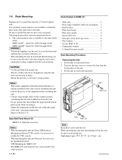
...unit into Sony LMS (Library Management System) VTR console, it from the rack, be sure to mount this unit, turn off the power of the unit. 3. m . VTR Mounting kit: BKFC-53/3 . The RMM-130 rack mount kit also can be used for the center position. 1-4 (E) Parts Packed in ...to remove the feet from the rack. . When other rail of low strength may drop the unit and cause the risk of the unit's operating temperature. (Refer to use of the slide rails to modify the VTR console. . Slide rails 2 . L-shaped hexagon wrench 1 Rack Mounting Procedure . Connect long enough cables ...
...unit into Sony LMS (Library Management System) VTR console, it from the rack, be sure to mount this unit, turn off the power of the unit. 3. m . VTR Mounting kit: BKFC-53/3 . The RMM-130 rack mount kit also can be used for the center position. 1-4 (E) Parts Packed in ...to remove the feet from the rack. . When other rail of low strength may drop the unit and cause the risk of the unit's operating temperature. (Refer to use of the slide rails to modify the VTR console. . Slide rails 2 . L-shaped hexagon wrench 1 Rack Mounting Procedure . Connect long enough cables ...
Installation Manual
Page 16
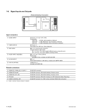
...), 600 Z termination, balanced XLR 3-pin x 1 Time code 0.5 to 18 V p-p, 10 kZ, balanced BNC x 2 in loop through connection Outside reference video signal SD : 0.3 V p-p, 75 Z, sync negative (Black burst or composite sync) HD : 0.6 V p-p, 75 Z, sync negative (Ternary SYNC) BNC x 2 (1 set : CH1/2, CH3/4) Digital audio AES/EBU format, complies with AES-3id-1995 BNC x 1 Serial digital interface (1.485 Gbit/s), complies with SMPTE...
...), 600 Z termination, balanced XLR 3-pin x 1 Time code 0.5 to 18 V p-p, 10 kZ, balanced BNC x 2 in loop through connection Outside reference video signal SD : 0.3 V p-p, 75 Z, sync negative (Black burst or composite sync) HD : 0.6 V p-p, 75 Z, sync negative (Ternary SYNC) BNC x 2 (1 set : CH1/2, CH3/4) Digital audio AES/EBU format, complies with AES-3id-1995 BNC x 1 Serial digital interface (1.485 Gbit/s), complies with SMPTE...
Installation Manual
Page 17
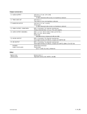
... control panel) Other Memory stick (Switch panel) XLR 3-pin x 2 (1 set : CH1, CH2) Analog audio +4 dBm (Standard) (600 Z load), low impedance, balanced XLR 3-pin x 1 Time code 2.2 V p-p, low impedance, balanced XLR 3-pin x 2 (1 set : L and R) Analog audio +4 dBm (Standard) (600 Z load), low impedance, balanced BNC x 3 (including 1 for character superimpose) Analog composite video 1.0 V p-p, 75 Z, sync negative BNC x 4 (1 set : CH1/2, CH3/4, CH5/6, and CH7/8) or BNC x 2 (1 set : CH1/2, CH3/4) Digital audio...
... control panel) Other Memory stick (Switch panel) XLR 3-pin x 2 (1 set : CH1, CH2) Analog audio +4 dBm (Standard) (600 Z load), low impedance, balanced XLR 3-pin x 1 Time code 2.2 V p-p, low impedance, balanced XLR 3-pin x 2 (1 set : L and R) Analog audio +4 dBm (Standard) (600 Z load), low impedance, balanced BNC x 3 (including 1 for character superimpose) Analog composite video 1.0 V p-p, 75 Z, sync negative BNC x 4 (1 set : CH1/2, CH3/4, CH5/6, and CH7/8) or BNC x 2 (1 set : CH1/2, CH3/4) Digital audio...
Installation Manual
Page 19
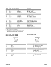
...Clear to change *2 Signal 36 IN O REC 37 OUT X REV LAMP 38 OUT O DA2 PRESET 39 OUT O DA1 PRESET 40 OUT X FWD LAMP 41 OUT O DA4 PRESET 42 OUT O DA3 PRESET 43 OUT X STOP 44 OUT O VIDEO PRESET 45 OUT O INSERT PRESET 46 OUT X STBY ON 47 OUT X PLAY... (Input) RXD ; Transmitted Data (Output) DTR ; Signal Ground DSR ; Request to the optional interface manual for changing the setting. Data Set Ready (Input) RTS ; (Continued) Pin No. REMOTE1-IN: 9-pin (female) REMOTE1-OUT: 9-pin (female) External view 5 1 Pin No. 1 2 3 4 5 6 7 8 9 96 Signal GND RM TX...
...Clear to change *2 Signal 36 IN O REC 37 OUT X REV LAMP 38 OUT O DA2 PRESET 39 OUT O DA1 PRESET 40 OUT X FWD LAMP 41 OUT O DA4 PRESET 42 OUT O DA3 PRESET 43 OUT X STOP 44 OUT O VIDEO PRESET 45 OUT O INSERT PRESET 46 OUT X STBY ON 47 OUT X PLAY... (Input) RXD ; Transmitted Data (Output) DTR ; Signal Ground DSR ; Request to the optional interface manual for changing the setting. Data Set Ready (Input) RTS ; (Continued) Pin No. REMOTE1-IN: 9-pin (female) REMOTE1-OUT: 9-pin (female) External view 5 1 Pin No. 1 2 3 4 5 6 7 8 9 96 Signal GND RM TX...
Installation Manual
Page 20
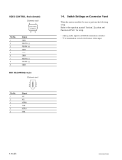
Refer to perform the following setup. Analog audio input level/600 Z termination switches . 75 Z termination switch of Parts" for setup. . Switch Settings on Connector Panel When the unit is installed, be sure to the operation manual "Section 2 Location and Function of reference video input 1-14 (E) HDW-1800/D1800 VIDEO CONTROL: 9-pin (female) External view 5 1 Pin No. 1 2 3 4 5 6 7 8 9 96 Signal GND RM TX (_) RM RX (+) GND -- GND RM TX (+) RM RX (_) GND HDV IN (OPTION): 6-pin External view 1 2 3 4 5 6 Pin No. 1 2 3 4 5 6 Signal VP VG NTPB TPB NTPA TPA 1-9.
Refer to perform the following setup. Analog audio input level/600 Z termination switches . 75 Z termination switch of Parts" for setup. . Switch Settings on Connector Panel When the unit is installed, be sure to the operation manual "Section 2 Location and Function of reference video input 1-14 (E) HDW-1800/D1800 VIDEO CONTROL: 9-pin (female) External view 5 1 Pin No. 1 2 3 4 5 6 7 8 9 96 Signal GND RM TX (_) RM RX (+) GND -- GND RM TX (+) RM RX (_) GND HDV IN (OPTION): 6-pin External view 1 2 3 4 5 6 Pin No. 1 2 3 4 5 6 Signal VP VG NTPB TPB NTPA TPA 1-9.
Installation Manual
Page 23
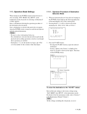
... the playback and recording operations correctly even though these operations are reset. 1-17 (E) Operation Procedure of the destination selection mode. DESTINATION SETTING * NO-SET 50:SYL 59.94:SYL 59.94:J Select DESTINATION. Pressing the F9 (SET) button accepts the selected destination. . Screen 2 appears after executing "M49: RESET ALL SETUP" in the Maintenance Manual Volume-1. m . Then turn off the POWER switch. When no destination is for the models for...
... the playback and recording operations correctly even though these operations are reset. 1-17 (E) Operation Procedure of the destination selection mode. DESTINATION SETTING * NO-SET 50:SYL 59.94:SYL 59.94:J Select DESTINATION. Pressing the F9 (SET) button accepts the selected destination. . Screen 2 appears after executing "M49: RESET ALL SETUP" in the Maintenance Manual Volume-1. m . Then turn off the POWER switch. When no destination is for the models for...

Installation Manual
Page 24
... the connector on state will damage the control panel. 4. 1-12. After pressing the unlock button, open , press the both side of the lower control panel unit and from your side before disconnecting the cable. Removing/Reattaching Lower Control Panel Unit 5. Removal 1. n Check the power of the VTR is turned off the power of removal. If the arms are visible from the cord holder...
... the connector on state will damage the control panel. 4. 1-12. After pressing the unlock button, open , press the both side of the lower control panel unit and from your side before disconnecting the cable. Removing/Reattaching Lower Control Panel Unit 5. Removal 1. n Check the power of the VTR is turned off the power of removal. If the arms are visible from the cord holder...

Installation Manual
Page 25
...19 (E) To enter the variable mode, press the VAR button. . After pressing the unlock buttons, open the lower control panel as shown in the figure. 3. Open the lower control panel. (Operation side up) 2. Check to switch the mode of the search dial on the ...mode selection plate in advance. (Refer to prohibit a manner of the mode selection plate, and then tighten the screw. Unlock button Unlock button Round hole The shaft is difficult to shuttle, jog, variable. Fully slide the mode selection plate in order to loosen the screw, remove the lower control panel unit in the direction...
...19 (E) To enter the variable mode, press the VAR button. . After pressing the unlock buttons, open the lower control panel as shown in the figure. 3. Open the lower control panel. (Operation side up) 2. Check to switch the mode of the search dial on the ...mode selection plate in advance. (Refer to prohibit a manner of the mode selection plate, and then tighten the screw. Unlock button Unlock button Round hole The shaft is difficult to shuttle, jog, variable. Fully slide the mode selection plate in order to loosen the screw, remove the lower control panel unit in the direction...
Installation Manual
Page 26
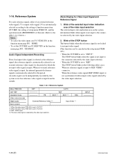
... (*2) REC Video output process Digital audio External Reference Video (*3) Input Video (*4) Servo system *1: When the setup menu ITEM-309 is set to "AUTO1". *2: When the setup menu ITEM-309 is set to "REF": The STOP button blinks in the following either of an external reference video signal (*3) or input video signal (*4) is automatically selected according to the setting of function menu item OUT REF, the setting of setup menu...
... (*2) REC Video output process Digital audio External Reference Video (*3) Input Video (*4) Servo system *1: When the setup menu ITEM-309 is set to "AUTO1". *2: When the setup menu ITEM-309 is set to "REF": The STOP button blinks in the following either of an external reference video signal (*3) or input video signal (*4) is automatically selected according to the setting of function menu item OUT REF, the setting of setup menu...
Installation Manual
Page 27
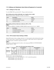
... this unit by setup menu of the VTR CONSTANT 1 to "0A" for Time Code To set to VTR) n The setup menu ITEM-610 : REGEN CONTROL MODE setting data must be set the TIME CODE, open the the P02 : TC page on the function menu. When Editing with Direct Machine-to-Machine (VTR to "AS&IN". Moreover, the change of VTR constant values are required when the operation mode is connected. 1-15. Data No...
... this unit by setup menu of the VTR CONSTANT 1 to "0A" for Time Code To set to VTR) n The setup menu ITEM-610 : REGEN CONTROL MODE setting data must be set the TIME CODE, open the the P02 : TC page on the function menu. When Editing with Direct Machine-to-Machine (VTR to "AS&IN". Moreover, the change of VTR constant values are required when the operation mode is connected. 1-15. Data No...
Installation Manual
Page 28
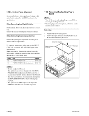
... adjusted in the REC mode, but it is shifted to the specifications. Be sure to blink the current setting value, and then turn the MULTI CONTROL knob. Refer to a Digital Switcher Fundamentally, the system phase adjustment is not necessary. Turn off the power and unplug the power cord before removing/reattaching the board. . To adjust the system phase of the extended setup menu. 1-16. When adjusting (i.e. Button Item Display...
... adjusted in the REC mode, but it is shifted to the specifications. Be sure to blink the current setting value, and then turn the MULTI CONTROL knob. Refer to a Digital Switcher Fundamentally, the system phase adjustment is not necessary. Turn off the power and unplug the power cord before removing/reattaching the board. . To adjust the system phase of the extended setup menu. 1-16. When adjusting (i.e. Button Item Display...

Installation Manual
Page 30
... a half turn to catch in the arrow direction. 6. m . Rotate the M gear of the threading motor block in direction of arrow shown in the arrow direction of the label until the cassette is slacken. 12. Pull the ME wire for a few times with short steps in the direction of a tape guide. . Pull...wind up the tape inside the cassette. Be careful for a few times with the T real table. Open the lower control panel. 13. 5. Release the lock of the board holder and open the AE31 board in parts such as a flange of arrow shown in the state to wind manually the tape. 7. Check ...
... a half turn to catch in the arrow direction. 6. m . Rotate the M gear of the threading motor block in direction of arrow shown in the arrow direction of the label until the cassette is slacken. 12. Pull the ME wire for a few times with short steps in the direction of a tape guide. . Pull...wind up the tape inside the cassette. Be careful for a few times with the T real table. Open the lower control panel. 13. 5. Release the lock of the board holder and open the AE31 board in parts such as a flange of arrow shown in the state to wind manually the tape. 7. Check ...
Installation Manual
Page 31
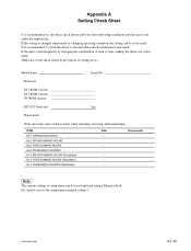
... (Resettable) H13: TAPE RUNNING HOURS (Resettable) H14: THREADING COUNTER (Resettable) Date Hours meter n The current settings of setup menu can be saved and read using a Memory Stick. If the unit is used frequently by changing operating condition, the setting can be reset easily. For details, refer to the unit when check, maintenance and repair. Appendix A Setting Check Sheet It is recommended to copy these check sheets...
... (Resettable) H13: TAPE RUNNING HOURS (Resettable) H14: THREADING COUNTER (Resettable) Date Hours meter n The current settings of setup menu can be saved and read using a Memory Stick. If the unit is used frequently by changing operating condition, the setting can be reset easily. For details, refer to the unit when check, maintenance and repair. Appendix A Setting Check Sheet It is recommended to copy these check sheets...
Installation Manual
Page 33
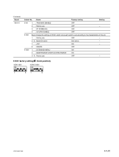
(Continued) Board SS-101 Switch No. : Name Factory setting Setting S101 S1501 S1502 1 : TRACKING ENABLE OFF 2 : Factory use OFF _ 3 : DT WOBBLING OFF 4 : SV ERR DISABLE OFF Never change the settings of S1501 switch since each switch is set according to the characteristics of the unit. 1 : Factory use OFF _ 2 - 6 : Model ID switch See below. _ 7 : J/SY ON _ 8 : 525/625 OFF 1 : EXTENDED MENU ON 2 : MAINTENANCE MODE ACCESS ENABLE ON 3 - 8 : Factory use OFF _ S1501 factory setting ( \ : Knob position) HDW-1800 ON HDW-D1800 ON 1 8 1 8 HDW-1800/D1800 A-3 (E)
(Continued) Board SS-101 Switch No. : Name Factory setting Setting S101 S1501 S1502 1 : TRACKING ENABLE OFF 2 : Factory use OFF _ 3 : DT WOBBLING OFF 4 : SV ERR DISABLE OFF Never change the settings of S1501 switch since each switch is set according to the characteristics of the unit. 1 : Factory use OFF _ 2 - 6 : Model ID switch See below. _ 7 : J/SY ON _ 8 : 525/625 OFF 1 : EXTENDED MENU ON 2 : MAINTENANCE MODE ACCESS ENABLE ON 3 - 8 : Factory use OFF _ S1501 factory setting ( \ : Knob position) HDW-1800 ON HDW-D1800 ON 1 8 1 8 HDW-1800/D1800 A-3 (E)
Installation Manual
Page 36
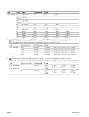
... track is displayed only during playback of the function menu page P100 : AUD MONI is available with the setup menu ITEM-833 (CUE AUDIO INPUT SELECT). n F5 (TRCK CHG) of MPEG IMX to allow selective setting (CH-5 to CH-8). Page Channel monitored Factory setting Setting P100 : AUD... CH-7 [||] CH-4 [||] CH-8 [||] CH-4 [||] CH-8 A-6 (E) HDW-1800/D1800 Page Button Name Factory setting Setting P08 : AUD INP F1 EMPHASIS F2 *3 AUD MIX (→P102) F3 *4 AUD MONI (→P100) F4 MT.SCALE F5 _ F6 AUDIO SG OFF _ _ FULL OFF [||] ON _ _ [||] FULL [||] OFF [||] OFF [||] FINE ...
... track is displayed only during playback of the function menu page P100 : AUD MONI is available with the setup menu ITEM-833 (CUE AUDIO INPUT SELECT). n F5 (TRCK CHG) of MPEG IMX to allow selective setting (CH-5 to CH-8). Page Channel monitored Factory setting Setting P100 : AUD... CH-7 [||] CH-4 [||] CH-8 [||] CH-4 [||] CH-8 A-6 (E) HDW-1800/D1800 Page Button Name Factory setting Setting P08 : AUD INP F1 EMPHASIS F2 *3 AUD MIX (→P102) F3 *4 AUD MONI (→P100) F4 MT.SCALE F5 _ F6 AUDIO SG OFF _ _ FULL OFF [||] ON _ _ [||] FULL [||] OFF [||] OFF [||] FINE ...


