
Installation Manual
Page 4
... als klein chemisch afval (KCA). Gooi de batterij niet weg maar lever deze in de Onderhoudshandleiding. Attention-when the product is installed in Taiwan only 2 (P) HDW-1800/D1800 Install the equipment while taking the operating temperature of the equipment into consideration For the operating temperature of the equipment, refer to obtain proper...
... als klein chemisch afval (KCA). Gooi de batterij niet weg maar lever deze in de Onderhoudshandleiding. Attention-when the product is installed in Taiwan only 2 (P) HDW-1800/D1800 Install the equipment while taking the operating temperature of the equipment into consideration For the operating temperature of the equipment, refer to obtain proper...
Installation Manual
Page 5
... is Connected 1-21 (E) 1-15-1. VTR Constant Values Settings of Destination Selection Mode 1-17 (E) 1-12. Removing/Reattaching Plug-in Tape Slacking 1-23 (E) Appendix A Setting Check Sheet HDW-1800/D1800 1 (E) Installation Procedure 1-1 (E) 1-2. Switch Settings on Connector Panel 1-14 (E) 1-10. Taking Out the Cassette in Board 1-22 (E) 1-17. Installation Space 1-3 (E) 1-6. Power Supply 1-2 (E) 1-4-1. Operation Mode Settings...
... is Connected 1-21 (E) 1-15-1. VTR Constant Values Settings of Destination Selection Mode 1-17 (E) 1-12. Removing/Reattaching Plug-in Tape Slacking 1-23 (E) Appendix A Setting Check Sheet HDW-1800/D1800 1 (E) Installation Procedure 1-1 (E) 1-2. Switch Settings on Connector Panel 1-14 (E) 1-10. Taking Out the Cassette in Board 1-22 (E) 1-17. Installation Space 1-3 (E) 1-6. Power Supply 1-2 (E) 1-4-1. Operation Mode Settings...
Installation Manual
Page 6
... manuals Besides this "installation manual", the following manuals are available for this unit.) This manual is the installation manual of the HD Digital Videocassette Recorder HDW-1800/D1800. "Semiconductor Pin Assignments" CD-ROM (Available on request) Volume-1 : Service Instruction Volume-2 : Parts List, Block Diagrams, and Board Layouts Volume-3 : Schematic Diagrams These manuals... thus should be used in Broadcast and Professional equipment. This manual is intended for semiconductors used together with this unit. . Part number: 9-968-546-0X 2 (E) HDW-1800/D1800
... manuals Besides this "installation manual", the following manuals are available for this unit.) This manual is the installation manual of the HD Digital Videocassette Recorder HDW-1800/D1800. "Semiconductor Pin Assignments" CD-ROM (Available on request) Volume-1 : Service Instruction Volume-2 : Parts List, Block Diagrams, and Board Layouts Volume-3 : Schematic Diagrams These manuals... thus should be used in Broadcast and Professional equipment. This manual is intended for semiconductors used together with this unit. . Part number: 9-968-546-0X 2 (E) HDW-1800/D1800
Installation Manual
Page 7
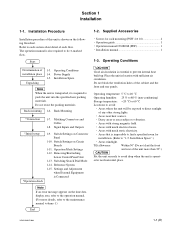
... the front and rear of each section about detail of the unit more details, refer to avoid drop when the unit is also required to "1-5. HDW-1800/D1800 1-1 (E) Refer to direct sunlight of the cabinet and the front and rear panels. Rack Mounting *Connection 1-7. Matching Connectors and Cables 1-8. Switch Settings on the...
... the front and rear of each section about detail of the unit more details, refer to avoid drop when the unit is also required to "1-5. HDW-1800/D1800 1-1 (E) Refer to direct sunlight of the cabinet and the front and rear panels. Rack Mounting *Connection 1-7. Matching Connectors and Cables 1-8. Switch Settings on the...

Installation Manual
Page 8
... only when connecting the AC power. Voltage and Power Requirements This unit's power line has a switching regulator. To get a power cord, please contact your local Sony Sales Office/Service Center. and Canada: 1 Power cord 125 V 10 A (2.4 m): ! 1-551-812-31 2 Plug holder (Brown): 3-613-640-01... 10 A (1.8 m): 2 Plug holder (Brown): 1 2 ! 1-783-481-42 3-613-640-01 AC inlet If the unit is commensurate with a power cord. HDW-1800/D1800 c Be sure to 240 V ± 10 % Power frequency: 50 Hz or 60 Hz Power consumption: Maximum 170 W (With all of the presumed optional ...
... only when connecting the AC power. Voltage and Power Requirements This unit's power line has a switching regulator. To get a power cord, please contact your local Sony Sales Office/Service Center. and Canada: 1 Power cord 125 V 10 A (2.4 m): ! 1-551-812-31 2 Plug holder (Brown): 3-613-640-01... 10 A (1.8 m): 2 Plug holder (Brown): 1 2 ! 1-783-481-42 3-613-640-01 AC inlet If the unit is commensurate with a power cord. HDW-1800/D1800 c Be sure to 240 V ± 10 % Power frequency: 50 Hz or 60 Hz Power consumption: Maximum 170 W (With all of the presumed optional ...

Installation Manual
Page 9
... 174 19.5 31.5 364 427 n Remove the feet when rack mounting. 12.7 34 123.8 263.5 415.9 48 457.5 Dimensions when Rack-Mounting (38.5) Unit : mm HDW-1800/D1800 1-3 (E) n This unit is recommended for service operation. Leave a space around the unit for inspection with the upper lid removed. Moreover, an air flow that...
... 174 19.5 31.5 364 427 n Remove the feet when rack mounting. 12.7 34 123.8 263.5 415.9 48 457.5 Dimensions when Rack-Mounting (38.5) Unit : mm HDW-1800/D1800 1-3 (E) n This unit is recommended for service operation. Leave a space around the unit for inspection with the upper lid removed. Moreover, an air flow that...
Installation Manual
Page 10
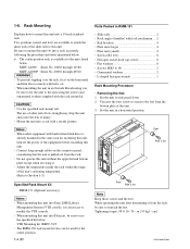
... toppling over the rack, fix it is already mounted in a horizontal position. The use the specified kit below . When mounting this unit into Sony LMS (Library Management System) VTR console, it on the connector panel, considering that the unit is available for the center position. 1-4 (E) Parts... the inner rails of the unit's operating temperature. (Refer to reattach the feet. Rail brackets 4 . Plate nuts (small 4 . cm} HDW-1800/D1800 When installing the unit in RMM-131 . The RMM-130 rack mount kit also can be sure to Section 1-3.) Specified Rack Mount Kit RMM...
... toppling over the rack, fix it is already mounted in a horizontal position. The use the specified kit below . When mounting this unit into Sony LMS (Library Management System) VTR console, it on the connector panel, considering that the unit is available for the center position. 1-4 (E) Parts... the inner rails of the unit's operating temperature. (Refer to reattach the feet. Rail brackets 4 . Plate nuts (small 4 . cm} HDW-1800/D1800 When installing the unit in RMM-131 . The RMM-130 rack mount kit also can be sure to Section 1-3.) Specified Rack Mount Kit RMM...

Installation Manual
Page 11
...other than actually used for fixing the rack angles. . Inner rail B4 x 6 Rack angle PSW4 x 16 n When replacing a 5U size Sony VTR with stop washers are fastened, rack mounting will cause a malfunction of the unit. Remove the four screws from both sides (left and right)... x 6) screws when attaching the inner rail. Attach the two rack angles to the screw holes other -sized screws may cause a malfunction. . cm} n . HDW-1800/D1800 PSW 4 x 16 Rack angle Fig.1 For RMM-130 (Left side) Rack angle 1-5 (E) Attaching the inner rails 4. Intermediate rail Inner rail A Stopper B...
...other than actually used for fixing the rack angles. . Inner rail B4 x 6 Rack angle PSW4 x 16 n When replacing a 5U size Sony VTR with stop washers are fastened, rack mounting will cause a malfunction of the unit. Remove the four screws from both sides (left and right)... x 6) screws when attaching the inner rail. Attach the two rack angles to the screw holes other -sized screws may cause a malfunction. . cm} n . HDW-1800/D1800 PSW 4 x 16 Rack angle Fig.1 For RMM-130 (Left side) Rack angle 1-5 (E) Attaching the inner rails 4. Intermediate rail Inner rail A Stopper B...

Installation Manual
Page 12
... nut (large) Outer rail Rail bracket Intermediate rail Ball retainer B4 x 8 13. cm} Rack Rail bracket Outer rail 50 to 55 mm Rack angle B4 x 8 1-6 (E) HDW-1800/D1800 Loosely attaching the rail brackets 10. Fully tighten the eight screws (B4 x 8) fixing the four rail brackets. .
... nut (large) Outer rail Rail bracket Intermediate rail Ball retainer B4 x 8 13. cm} Rack Rail bracket Outer rail 50 to 55 mm Rack angle B4 x 8 1-6 (E) HDW-1800/D1800 Loosely attaching the rail brackets 10. Fully tighten the eight screws (B4 x 8) fixing the four rail brackets. .

Installation Manual
Page 13
... each ball retainer of intermediate rails on both sides (left and right) in the direction of each stopper of the rack angles. 1-7 (E) Release button Stopper HDW-1800/D1800 Intermediate rail Stopper Inner rail Release button n Pushing the unit in rack c Be sure to catch your finger or hand in step 12 using...
... each ball retainer of intermediate rails on both sides (left and right) in the direction of each stopper of the rack angles. 1-7 (E) Release button Stopper HDW-1800/D1800 Intermediate rail Stopper Inner rail Release button n Pushing the unit in rack c Be sure to catch your finger or hand in step 12 using...

Installation Manual
Page 14
Push the unit in the depths of the rack. Tightening torque: 120 x 10_2 N . Release button Ornamental washer RK5 x 14 RK5 x 14 Release button Ornamental washer 1-8 (E) HDW-1800/D1800 Put down the unit on the floor or other, being careful not to pull the rack angles and confirm that the slide rails move ...
Push the unit in the depths of the rack. Tightening torque: 120 x 10_2 N . Release button Ornamental washer RK5 x 14 RK5 x 14 Release button Ornamental washer 1-8 (E) HDW-1800/D1800 Put down the unit on the floor or other, being careful not to pull the rack angles and confirm that the slide rails move ...

Installation Manual
Page 15
...SHELL 9P Specified by optional kit BNC 75Z, MALE *2 BNC 75Z, MALE *3 JM-60 stereo phone plug Sony part No. 1-508-084-00 1-508-083-00 1-569-370-12 1-569-370-12 1-565-516-11...12 _ Remarks Upper control panel connector *1: Coaxial cable length : max. 600 meters (Reference value based on HDW series) It is recommended to connect the BELDEN 8281 cable or equivalent to this connector. *2: Coaxial cable length... to this connector. *3: Coaxial cable length : max. 200 meters (Reference value based on HDW series) It is recommended to connect the BELDEN 8281 cable or equivalent to the connector of this...
...SHELL 9P Specified by optional kit BNC 75Z, MALE *2 BNC 75Z, MALE *3 JM-60 stereo phone plug Sony part No. 1-508-084-00 1-508-083-00 1-569-370-12 1-569-370-12 1-565-516-11...12 _ Remarks Upper control panel connector *1: Coaxial cable length : max. 600 meters (Reference value based on HDW series) It is recommended to connect the BELDEN 8281 cable or equivalent to this connector. *2: Coaxial cable length... to this connector. *3: Coaxial cable length : max. 200 meters (Reference value based on HDW series) It is recommended to connect the BELDEN 8281 cable or equivalent to the connector of this...
Installation Manual
Page 16
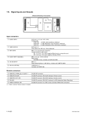
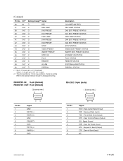
... ISR (Interactive Status Reporting) 4 VIDEO CONTROL (9P) D-SUB 9P connector for a TBC remote controller (HKDV-900) connection *** : Refer to Optional "Interface manual" for details. 1-10 (E) HDW-1800/D1800 Signal Inputs and Outputs Reduced drawing of rear panel 3 1 2 5 6 4 Input connectors 1 AUDIO INPUT 1 TIME CODE IN 2 REF.
... ISR (Interactive Status Reporting) 4 VIDEO CONTROL (9P) D-SUB 9P connector for a TBC remote controller (HKDV-900) connection *** : Refer to Optional "Interface manual" for details. 1-10 (E) HDW-1800/D1800 Signal Inputs and Outputs Reduced drawing of rear panel 3 1 2 5 6 4 Input connectors 1 AUDIO INPUT 1 TIME CODE IN 2 REF.
Installation Manual
Page 17
... & ITU-R BT.656 JM-60 stereo phone jack Analog audio up to _12 dBu (8 Z load), unbalanced Memory stick x 1 Applicable memory stick (8 MB to 128 MB) HDW-1800/D1800 1-11 (E)
... & ITU-R BT.656 JM-60 stereo phone jack Analog audio up to _12 dBu (8 Z load), unbalanced Memory stick x 1 Applicable memory stick (8 MB to 128 MB) HDW-1800/D1800 1-11 (E)
Installation Manual
Page 18
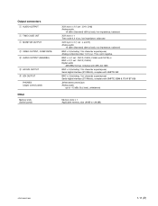
... DATA RESET REMOTE2 SETTING DATA RESET STATUS ALL REC INHIBIT ALL REC INHIBIT STATUS GND PLAY CLOSURE SW (PLAY) STOP CLOSURE SW (STOP) (Continue) 1-12 (E) HDW-1800/D1800 REMOTE 2 PARALLEL I /O *1 Setting change *2 Signal Description 1 IN O 2 OUT X 3 OUT X 4 OUT X 5 OUT X 6 OUT X 7 OUT X 8 OUT X 9 OUT X 10 OUT O 11 OUT O 12 OUT O 13 OUT O 14...
... DATA RESET REMOTE2 SETTING DATA RESET STATUS ALL REC INHIBIT ALL REC INHIBIT STATUS GND PLAY CLOSURE SW (PLAY) STOP CLOSURE SW (STOP) (Continue) 1-12 (E) HDW-1800/D1800 REMOTE 2 PARALLEL I /O *1 Setting change *2 Signal Description 1 IN O 2 OUT X 3 OUT X 4 OUT X 5 OUT X 6 OUT X 7 OUT X 8 OUT X 9 OUT X 10 OUT O 11 OUT O 12 OUT O 13 OUT O 14...
Installation Manual
Page 19
... kZ pull up to +5 V (close/open) Output ; 10 kZ pull up to +5 V (0 V or open) *2: The pins described as O mark are possible to Send (Input) NC HDW-1800/D1800 1-13 (E) Data Carrier Detect (Input) RXD ; Request to the optional interface manual for changing the setting. Refer to Send (Output) CTS ; Data Set Ready...
... kZ pull up to +5 V (close/open) Output ; 10 kZ pull up to +5 V (0 V or open) *2: The pins described as O mark are possible to Send (Input) NC HDW-1800/D1800 1-13 (E) Data Carrier Detect (Input) RXD ; Request to the optional interface manual for changing the setting. Refer to Send (Output) CTS ; Data Set Ready...
Installation Manual
Page 20
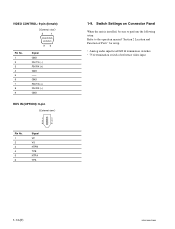
VIDEO CONTROL: 9-pin (female) External view 5 1 Pin No. 1 2 3 4 5 6 7 8 9 96 Signal GND RM TX (_) RM RX (+) GND -- GND RM TX (+) RM RX (_) GND HDV IN (OPTION): 6-pin External view 1 2 3 4 5 6 Pin No. 1 2 3 4 5 6 Signal VP VG NTPB TPB NTPA TPA 1-9. Switch Settings on Connector Panel When the unit is installed, be sure to the operation manual "Section 2 Location and Function of reference video input 1-14 (E) HDW-1800/D1800 Refer to perform the following setup. Analog audio input level/600 Z termination switches . 75 Z termination switch of Parts" for setup. .
VIDEO CONTROL: 9-pin (female) External view 5 1 Pin No. 1 2 3 4 5 6 7 8 9 96 Signal GND RM TX (_) RM RX (+) GND -- GND RM TX (+) RM RX (_) GND HDV IN (OPTION): 6-pin External view 1 2 3 4 5 6 Pin No. 1 2 3 4 5 6 Signal VP VG NTPB TPB NTPA TPA 1-9. Switch Settings on Connector Panel When the unit is installed, be sure to the operation manual "Section 2 Location and Function of reference video input 1-14 (E) HDW-1800/D1800 Refer to perform the following setup. Analog audio input level/600 Z termination switches . 75 Z termination switch of Parts" for setup. .
Installation Manual
Page 21
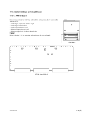
1-10. Audio input, output, and monitor output . Monitor output reference level . Switch Settings on the APR-80 board. . Monitor output level, fixed/variable selection n Refer to Section 1-16 for removing and reattaching the plug-in boards. < Top View > A B C D E F G H J APR-80 K L M N P 1 S1901 S1900 A S1902 2 S2001 S2000 3 4 5 6 APR-80 Board (Side A) HDW-1800/D1800 1-15 (E) Audio output reference level . APR-80 Board If necessary, perform the following audio-related settings using the switches on Circuit Boards 1-10-1. Audio input reference level .
1-10. Audio input, output, and monitor output . Monitor output reference level . Switch Settings on the APR-80 board. . Monitor output level, fixed/variable selection n Refer to Section 1-16 for removing and reattaching the plug-in boards. < Top View > A B C D E F G H J APR-80 K L M N P 1 S1901 S1900 A S1902 2 S2001 S2000 3 4 5 6 APR-80 Board (Side A) HDW-1800/D1800 1-15 (E) Audio output reference level . APR-80 Board If necessary, perform the following audio-related settings using the switches on Circuit Boards 1-10-1. Audio input reference level .
Installation Manual
Page 22
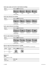
.... S1902-1, 2 Switch state (\ : Knob position) 20 dB (Factory setting) 18 dB Audio input reference level settings Ref. Ref. S1900, S1901 Switch state All OFF 1-16 (E) HDW-1800/D1800 No. Channel L Ref. S1902-5, 6 Switch state (\ : Knob position) _3 dBm/600 Z _20 dBm/600 Z +4 dBm/600 Z (Factory setting) 0 dBm/600 Z Monitor output reference level...
.... S1902-1, 2 Switch state (\ : Knob position) 20 dB (Factory setting) 18 dB Audio input reference level settings Ref. Ref. S1900, S1901 Switch state All OFF 1-16 (E) HDW-1800/D1800 No. Channel L Ref. S1902-5, 6 Switch state (\ : Knob position) _3 dBm/600 Z _20 dBm/600 Z +4 dBm/600 Z (Factory setting) 0 dBm/600 Z Monitor output reference level...
Installation Manual
Page 23
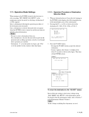
... When turning on the POWER switch for the countries other than Japan. 1-11-1. For details about 10 seconds as shown in the Maintenance Manual Volume-1. HDW-1800/D1800 Screen 2 About 10 seconds DESTINATION SET COMPLETE 59.94:SYL TURN OFF/ON POWER !! Once a destination is selected, this mode does not appear when...
... When turning on the POWER switch for the countries other than Japan. 1-11-1. For details about 10 seconds as shown in the Maintenance Manual Volume-1. HDW-1800/D1800 Screen 2 About 10 seconds DESTINATION SET COMPLETE 59.94:SYL TURN OFF/ON POWER !! Once a destination is selected, this mode does not appear when...

