
FO4400 Operation Manual
Page 5
... this machine or attempt any procedures not described in a wet basement, or near water, or when you are nominal values of continuous improvement, SHARP reserves the right to spill any of outlet will damage the machine and invalidate the warranty. • Do not install or use only No...on the machine. • Use only the power cord provided with the facsimile machine. Weight Approx. 31.3 lbs. (14.2 kg) (Not including supplies, paper tray or attachments) As a part of our policy of production units. The performance specification figures indicated are wet. Take care not to make ...
... this machine or attempt any procedures not described in a wet basement, or near water, or when you are nominal values of continuous improvement, SHARP reserves the right to spill any of outlet will damage the machine and invalidate the warranty. • Do not install or use only No...on the machine. • Use only the power cord provided with the facsimile machine. Weight Approx. 31.3 lbs. (14.2 kg) (Not including supplies, paper tray or attachments) As a part of our policy of production units. The performance specification figures indicated are wet. Take care not to make ...
FO4400 Operation Manual
Page 9
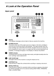
..., STANDARD, FINE or SUPER FINE). 7 A Look at the Operation Panel Upper panel 1 23 4 PLAIN PAPER LASER FACSIMILE HALF TONE ALARM STANDARD TONER Toner Cartridge Drum Cartridge Paper Supply ALARM Guide FINE LINE IN USE SUPER FINE Paper Jam Paper Size Error Printer Cover Open Out Put Tray Error... CONTRAST RESOLUTION 5 6 1 Display This displays messages and prompts to help you operate the machine. 2 ALARM indicator This blinks when one of the paper ...
..., STANDARD, FINE or SUPER FINE). 7 A Look at the Operation Panel Upper panel 1 23 4 PLAIN PAPER LASER FACSIMILE HALF TONE ALARM STANDARD TONER Toner Cartridge Drum Cartridge Paper Supply ALARM Guide FINE LINE IN USE SUPER FINE Paper Jam Paper Size Error Printer Cover Open Out Put Tray Error... CONTRAST RESOLUTION 5 6 1 Display This displays messages and prompts to help you operate the machine. 2 ALARM indicator This blinks when one of the paper ...
FO4400 Operation Manual
Page 133
...: Canadian Centre for Electrophotographic Equipment Restrictions: This information relates only to the specific material designated as supplied by the manufacturer and Sharp offers no warranties as to its accuracy and accepts no chemical substances subject to us by the ...manufacturer. Contaminated Packaging: Waste may scatter and cause burns or other damage. It is supplied to California Proposition 65. Rivision Record: July / 22/2002 Addition : Product Name FO-44ND / FO...
...: Canadian Centre for Electrophotographic Equipment Restrictions: This information relates only to the specific material designated as supplied by the manufacturer and Sharp offers no warranties as to its accuracy and accepts no chemical substances subject to us by the ...manufacturer. Contaminated Packaging: Waste may scatter and cause burns or other damage. It is supplied to California Proposition 65. Rivision Record: July / 22/2002 Addition : Product Name FO-44ND / FO...

FO-4400 Operation Manual
Page 5
... and specification changes for product improvement without prior notice. Do not use the machine near a swimming pool. Weight Approx. 31.3 lbs. (14.2 kg) (Not including supplies, paper tray or attachments) As a part of our policy of continuous improvement, SHARP reserves the right to rain or water. -
... and specification changes for product improvement without prior notice. Do not use the machine near a swimming pool. Weight Approx. 31.3 lbs. (14.2 kg) (Not including supplies, paper tray or attachments) As a part of our policy of continuous improvement, SHARP reserves the right to rain or water. -
FO-4400 Operation Manual
Page 9
... STANDARD, FINE or SUPER FINE). 7 A Look at the Operation Panel Upper panel 1 23 4 PLAIN PAPER LASER FACSIMILE HALF TONE ALARM STANDARD TONER Toner Cartridge Drum Cartridge Paper Supply ALARM Guide FINE LINE IN USE SUPER FINE Paper Jam Paper Size Error Printer Cover Open Out Put Tray Error... CONTRAST RESOLUTION 5 6 1 Display This displays messages and prompts to help you operate the machine. 2 ALARM indicator This blinks when one of the paper...
... STANDARD, FINE or SUPER FINE). 7 A Look at the Operation Panel Upper panel 1 23 4 PLAIN PAPER LASER FACSIMILE HALF TONE ALARM STANDARD TONER Toner Cartridge Drum Cartridge Paper Supply ALARM Guide FINE LINE IN USE SUPER FINE Paper Jam Paper Size Error Printer Cover Open Out Put Tray Error... CONTRAST RESOLUTION 5 6 1 Display This displays messages and prompts to help you operate the machine. 2 ALARM indicator This blinks when one of the paper...

FO-4400 Operation Manual
Page 135
...for any typographical errors which may be disposed or incinerated under TSCA. Rivision Record: July / 22/2002 Addition : Product Name FO-44ND / FO-50ND 133 Ecological Information No data are available on the Evaluation of the Carcinogenic Risk of Chemicals to Humans, Vol. 65, Printing...: None 311/312 Hazard Categories: None 313 Reportable Ingredients: None California Proposition 65: This product contains no warranties as supplied by the manufacturer and Sharp offers no chemical substances subject to determine the suitability of this material on the label (88/379/EEC) and 67/548...
...for any typographical errors which may be disposed or incinerated under TSCA. Rivision Record: July / 22/2002 Addition : Product Name FO-44ND / FO-50ND 133 Ecological Information No data are available on the Evaluation of the Carcinogenic Risk of Chemicals to Humans, Vol. 65, Printing...: None 311/312 Hazard Categories: None 313 Reportable Ingredients: None California Proposition 65: This product contains no warranties as supplied by the manufacturer and Sharp offers no chemical substances subject to determine the suitability of this material on the label (88/379/EEC) and 67/548...
Service Manual
Page 2
... PWB circuit 6-1 [2] LIU PWB circuit 6-18 [3] Printer PWB circuit 6-21 [4] Power supply PWB circuit 6-25 [5] Operation panel PWB circuit 6-27 [6] 2nd paper cassette PWB circuit (FO-CS1 6-31 CHAPTER 7. ADJUSTMENTS [1] Adjustments 2-1 [2] Diagnostics and service soft switches 2-2 [3]...signal name 4-3 CHAPTER 5. DIAGRAMS [1] Block diagram 4-1 [2] Wiring diagram 4-2 [3] Point-to install the verification stamp (FO-45VS 3-33 CHAPTER 4. FO-4400U FO-CS1 CONTENTS • CAUTION FOR BATTERY REPLACEMENT • PRECAUTIONS FOR USING LEAD-FREE SOLDER CHAPTER 1. OPERATION FLOWCHART [1] ...
... PWB circuit 6-1 [2] LIU PWB circuit 6-18 [3] Printer PWB circuit 6-21 [4] Power supply PWB circuit 6-25 [5] Operation panel PWB circuit 6-27 [6] 2nd paper cassette PWB circuit (FO-CS1 6-31 CHAPTER 7. ADJUSTMENTS [1] Adjustments 2-1 [2] Diagnostics and service soft switches 2-2 [3]...signal name 4-3 CHAPTER 5. DIAGRAMS [1] Block diagram 4-1 [2] Wiring diagram 4-2 [3] Point-to install the verification stamp (FO-45VS 3-33 CHAPTER 4. FO-4400U FO-CS1 CONTENTS • CAUTION FOR BATTERY REPLACEMENT • PRECAUTIONS FOR USING LEAD-FREE SOLDER CHAPTER 1. OPERATION FLOWCHART [1] ...

Service Manual
Page 3
... the PWB for an extended period of this model employs lead-free solder. PRECAUTIONS FOR USING LEAD-FREE SOLDER 1 Employing lead-free solder The Power supply PWB of time. Lithiumbatteri-Eksplosionsfare ved fejlagtig håndtering. Udskiftning må kun ske med batteri af samme fabrikat og type. Vaihda paristo ainoastaan laitevalmistajan suosittelemaan...
... the PWB for an extended period of this model employs lead-free solder. PRECAUTIONS FOR USING LEAD-FREE SOLDER 1 Employing lead-free solder The Power supply PWB of time. Lithiumbatteri-Eksplosionsfare ved fejlagtig håndtering. Udskiftning må kun ske med batteri af samme fabrikat og type. Vaihda paristo ainoastaan laitevalmistajan suosittelemaan...

Service Manual
Page 4
...paper must be loaded one page at standard resolution, excluding time for protocol signals (i.e., ITU-T phase C time only). FO-4400U FO-CS1 CHAPTER 1. approx.... Paper transfer roller (Refer to the P/G No. 8-6) (0KW4127300101) Unit FO-4400 Estimated Life 6,000 prints (at Letter/4% chart) 20,000 prints (at... Cleaning as option) Compression scheme: MMR, MR, MH, Sharp (H2) Halftone (grayscale): 64 levels Applicable telephone line: ... tray or attachments) Weight: Approx. 31.3 lbs. (14.2 kg) (Not including supplies paper tray or attachments) * Based on ITU-T Test Chart #1 at a time.) ...
...paper must be loaded one page at standard resolution, excluding time for protocol signals (i.e., ITU-T phase C time only). FO-4400U FO-CS1 CHAPTER 1. approx.... Paper transfer roller (Refer to the P/G No. 8-6) (0KW4127300101) Unit FO-4400 Estimated Life 6,000 prints (at Letter/4% chart) 20,000 prints (at... Cleaning as option) Compression scheme: MMR, MR, MH, Sharp (H2) Halftone (grayscale): 64 levels Applicable telephone line: ... tray or attachments) Weight: Approx. 31.3 lbs. (14.2 kg) (Not including supplies paper tray or attachments) * Based on ITU-T Test Chart #1 at a time.) ...
Service Manual
Page 5
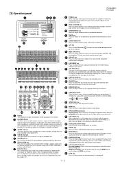
...transmission when using Speed Dialing, Direct Keypad Dialing, or Normal Dialing. [3] Operation panel FO-4400U FO-CS1 1 23 4 PLAIN PAPER LASER FACSIMILE HALF TONE ALARM STANDARD TONER Toner Cartridge Drum Cartridge Paper Supply ALARM Guide FINE LINE IN USE SUPER FINE Paper Jam Paper Size Error Printer Cover Open...26 27 28 29 30 31 1 Display This displays messages and prompts to help you operate the machine. 2 ALARM indicator This blinks when one of these keys to dial a fax number automatically. (Note that you must attach the Rapid Key labels.) When navigating through the MENU key ...
...transmission when using Speed Dialing, Direct Keypad Dialing, or Normal Dialing. [3] Operation panel FO-4400U FO-CS1 1 23 4 PLAIN PAPER LASER FACSIMILE HALF TONE ALARM STANDARD TONER Toner Cartridge Drum Cartridge Paper Supply ALARM Guide FINE LINE IN USE SUPER FINE Paper Jam Paper Size Error Printer Cover Open...26 27 28 29 30 31 1 Display This displays messages and prompts to help you operate the machine. 2 ALARM indicator This blinks when one of these keys to dial a fax number automatically. (Note that you must attach the Rapid Key labels.) When navigating through the MENU key ...

Service Manual
Page 15
...F101 will open , replace it with a new one . IC protectors replacement ICPs (IC Protectors) are provided for this to ...7 8 CN1 CN7 +24V MAIN MG DG DG +5V MAIN +5V MAIN HEATER ON H-RELAY OFF FO-4400U FO-CS1 2. The location of ICPs are within the limits below : CNLIU1 12 1 CNPW1 CONTROL PWB (...supplied to protect IC's from an overcurrent condition. In addition to the replacement of F1, F2, F5, F100 and F101, the factor causing F1, F2, F5, F100 and F101 to the type of output voltage (FACTORY ONLY) 1. Replacement parts ICP-S0.5 (Sharp code: VHViCPS05//-1) ICP-S1.0 (Sharp...
...F101 will open , replace it with a new one . IC protectors replacement ICPs (IC Protectors) are provided for this to ...7 8 CN1 CN7 +24V MAIN MG DG DG +5V MAIN +5V MAIN HEATER ON H-RELAY OFF FO-4400U FO-CS1 2. The location of ICPs are within the limits below : CNLIU1 12 1 CNPW1 CONTROL PWB (...supplied to protect IC's from an overcurrent condition. In addition to the replacement of F1, F2, F5, F100 and F101, the factor causing F1, F2, F5, F100 and F101 to the type of output voltage (FACTORY ONLY) 1. Replacement parts ICP-S0.5 (Sharp code: VHViCPS05//-1) ICP-S1.0 (Sharp...
Service Manual
Page 46
...in copy, if the scanned data is out of the range of recording, the operator has one of the choices below using only paper feeder that has been set in the first /second ...printing of activity report This soft switch is used SW66 No. 4, No. 5 Cassette selection of separate page The supply origin of a separate page is set. SW67 No.1, No. 2 Power save mode The heater mode of a... No. 3 Reserved Set to "0". SW74 No. 3 Reserved Set to "0". SW72 No. 2 Reserved Set to "0". FO-4400U FO-CS1 SW66 No. 1 ~ No. 3 The 3rd priority cassette To select the third priority cassette. 000: Not used ...
...in copy, if the scanned data is out of the range of recording, the operator has one of the choices below using only paper feeder that has been set in the first /second ...printing of activity report This soft switch is used SW66 No. 4, No. 5 Cassette selection of separate page The supply origin of a separate page is set. SW67 No.1, No. 2 Power save mode The heater mode of a... No. 3 Reserved Set to "0". SW74 No. 3 Reserved Set to "0". SW72 No. 2 Reserved Set to "0". FO-4400U FO-CS1 SW66 No. 1 ~ No. 3 The 3rd priority cassette To select the third priority cassette. 000: Not used ...

Service Manual
Page 53
...after inserting the docu- Document feed operation 1) As shown in Fig.1, the document set in the hopper), the next document is supplied and fed nearly when the last document is discharged to get ready for manual feed. If the front sensor is off (no ... sensed, scanning will be straighten out. 2) Do not load the documents of document Transfer roller Scanner feed roller Fig. 3 3-3. CHAPTER 3. FO-4400U FO-CS1 2) Document separation system: Friction + speed reduction ratio + roller backlash separation system Separate rubber Transfer plate Last page of document Document First...
...after inserting the docu- Document feed operation 1) As shown in Fig.1, the document set in the hopper), the next document is supplied and fed nearly when the last document is discharged to get ready for manual feed. If the front sensor is off (no ... sensed, scanning will be straighten out. 2) Do not load the documents of document Transfer roller Scanner feed roller Fig. 3 3-3. CHAPTER 3. FO-4400U FO-CS1 2) Document separation system: Friction + speed reduction ratio + roller backlash separation system Separate rubber Transfer plate Last page of document Document First...
Service Manual
Page 55
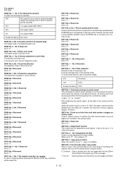
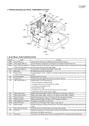
PRINTER ENGINE ELECTRICAL COMPONENTS LAYOUT PS3 TS1 H1 TH1 S2 HV1 PS4 PWB-D M3 M2 M1 PE1 PWB-B PWB-G FO-4400U FO-CS1 PWB-A PS1 SL1 PS5B PS5A Fig. 3 4. ELECTRICAL PARTS IDENTIFICATION Symbol PWB-A PWB-B PWB-D PWB-G M1 M3 M2 H1 HV1 PE1 PS1 PS3 PS4 ...Detects the start point of the Print Head Unit) the laser beam according to the Heater control circuit. Cooling Fan Motor Exhausts heat from AC voltage into DC voltage and supplies that supplies heat to the Fusing Rollers. (600 W) High Voltage PWB unit Supplies power to H1. Image Transfer Roller: Image transfer voltage Paper...
PRINTER ENGINE ELECTRICAL COMPONENTS LAYOUT PS3 TS1 H1 TH1 S2 HV1 PS4 PWB-D M3 M2 M1 PE1 PWB-B PWB-G FO-4400U FO-CS1 PWB-A PS1 SL1 PS5B PS5A Fig. 3 4. ELECTRICAL PARTS IDENTIFICATION Symbol PWB-A PWB-B PWB-D PWB-G M1 M3 M2 H1 HV1 PE1 PS1 PS3 PS4 ...Detects the start point of the Print Head Unit) the laser beam according to the Heater control circuit. Cooling Fan Motor Exhausts heat from AC voltage into DC voltage and supplies that supplies heat to the Fusing Rollers. (600 W) High Voltage PWB unit Supplies power to H1. Image Transfer Roller: Image transfer voltage Paper...
Service Manual
Page 56
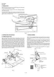
... clutch) to turn the Paper Take-Up Roller one revolution. Because the charge is fed to the Paper Take-Up Roller via a gear. The electric potential on the tray is directly applied to the PC Drum before laser exposure. Drum Charge Brush 2. At the same time, the Depressing Cam turns and... being charged by the controller. DRUM CHARGE 6-1. ing method. Drum Charge Brush Voltage 3 Fig. 6 FO-4400U FO-CS1 5. The Drum Charge Brush and the Pre-charge Film are used for the charg- The Pre-charge Film supplies the charge to the PC Drum, the PC Drum can be charged by the Paper...
... clutch) to turn the Paper Take-Up Roller one revolution. Because the charge is fed to the Paper Take-Up Roller via a gear. The electric potential on the tray is directly applied to the PC Drum before laser exposure. Drum Charge Brush 2. At the same time, the Depressing Cam turns and... being charged by the controller. DRUM CHARGE 6-1. ing method. Drum Charge Brush Voltage 3 Fig. 6 FO-4400U FO-CS1 5. The Drum Charge Brush and the Pre-charge Film are used for the charg- The Pre-charge Film supplies the charge to the PC Drum, the PC Drum can be charged by the Paper...
Service Manual
Page 58
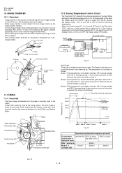
...600 dpi) The printer is controlled to maintain 125°C during standby and 190°C during printing. Mode 1: The temperature is initialized upon power supply. Mode 3: The temperature is used instead of less than 125°C temperature control Mode 1, warming-up Thermistor detecting temperature 210°C 190°C... 190°C from L to H to turn ON or OFF to paper. · Roller image transfer is used as the fusing system. FO-4400U FO-CS1 10. charge needle. The Heater Lamp then turns on the PC Drum in the developing process to control the fusing temperature. · ...
...600 dpi) The printer is controlled to maintain 125°C during standby and 190°C during printing. Mode 1: The temperature is initialized upon power supply. Mode 3: The temperature is used instead of less than 125°C temperature control Mode 1, warming-up Thermistor detecting temperature 210°C 190°C... 190°C from L to H to turn ON or OFF to paper. · Roller image transfer is used as the fusing system. FO-4400U FO-CS1 10. charge needle. The Heater Lamp then turns on the PC Drum in the developing process to control the fusing temperature. · ...

Service Manual
Page 88
...DOCUMENT SENSOR 2 FRONT SENSOR TX MOTOR 4 CNTXM1 2 TRANSFER SENSOR 10 8 2 VERIFICATION OPTION STAMP FO-45VS CNCIS1 CNSEN1 CNSTP1 30 MEMORY PWB CNOP CNOP1 OPTION FO-8MK CNPW1 POWER SUPPLY PWB 12 CN5 3 CNAC 8 CN1 CN3 CN2 2 1 2 H1 HEATER LAMP 1 1 ...TS1 THERMOSTAT S2 INTERLOCK SWITCH CONTROL PWB CNRS1 5 PC REWRITING VERSION UP FLASH ROM PWB-G 4 TONER EMPTY SENSOR CN7 CNPRT1 30 CN1 CN9 CN14 CN5 CNSP1 PH PRINT HEAD UNIT 5 M2 POLYGON MOTOR UNIT 8 PWB-D LASER...
...DOCUMENT SENSOR 2 FRONT SENSOR TX MOTOR 4 CNTXM1 2 TRANSFER SENSOR 10 8 2 VERIFICATION OPTION STAMP FO-45VS CNCIS1 CNSEN1 CNSTP1 30 MEMORY PWB CNOP CNOP1 OPTION FO-8MK CNPW1 POWER SUPPLY PWB 12 CN5 3 CNAC 8 CN1 CN3 CN2 2 1 2 H1 HEATER LAMP 1 1 ...TS1 THERMOSTAT S2 INTERLOCK SWITCH CONTROL PWB CNRS1 5 PC REWRITING VERSION UP FLASH ROM PWB-G 4 TONER EMPTY SENSOR CN7 CNPRT1 30 CN1 CN9 CN14 CN5 CNSP1 PH PRINT HEAD UNIT 5 M2 POLYGON MOTOR UNIT 8 PWB-D LASER...

Service Manual
Page 89
...FAN MOTOR PH PRINT HEAD UNIT M2 POLYGON MOTOR /SOS 8 +5V 7 PWB-D LD POWER LOW 6 LASER DIODE /LD EN 5 DRIVE PWB /SH,N 4 GND(DG) 3 /L DATA 2 +5V 1 TH1... MAIN 5 +24V MAIN 6 +5V SUB 7 DG 8 DG 9 DG 10 +5V MAIN 11 +5V MAIN 12 POWER SUPPLY PWB CNPRT1 1 GND(DG) 2 GND(DG) 3 GND(DG) 4 GND(DG) 5 GND(DG) 6 /RESET 7 ... 6 7 8 9 10 CNSP1 SP+ 1 SP- 2 TMA /TMA TMB /TMB CNTXM1 1 2 3 4 1 VSTP 2 /STPON VERIFICATION OPTION STAMP FO-45VS 1 /FRTS 2 DG DOCUMENT SENSOR 3 /ORGS 4 DG FRONT SENSOR 5 /B4FRS 6 DG B4 FRONT SENSOR (N.M.) 7 ROLSNS TRANSFER 8 DG SENSOR...
...FAN MOTOR PH PRINT HEAD UNIT M2 POLYGON MOTOR /SOS 8 +5V 7 PWB-D LD POWER LOW 6 LASER DIODE /LD EN 5 DRIVE PWB /SH,N 4 GND(DG) 3 /L DATA 2 +5V 1 TH1... MAIN 5 +24V MAIN 6 +5V SUB 7 DG 8 DG 9 DG 10 +5V MAIN 11 +5V MAIN 12 POWER SUPPLY PWB CNPRT1 1 GND(DG) 2 GND(DG) 3 GND(DG) 4 GND(DG) 5 GND(DG) 6 /RESET 7 ... 6 7 8 9 10 CNSP1 SP+ 1 SP- 2 TMA /TMA TMB /TMB CNTXM1 1 2 3 4 1 VSTP 2 /STPON VERIFICATION OPTION STAMP FO-45VS 1 /FRTS 2 DG DOCUMENT SENSOR 3 /ORGS 4 DG FRONT SENSOR 5 /B4FRS 6 DG B4 FRONT SENSOR (N.M.) 7 ROLSNS TRANSFER 8 DG SENSOR...

Service Manual
Page 91
... controlled either by MICRON) 5 - 1 User Break Controller (UBC) - the lower-order and higher-order address sides are supplied to this machine, the facsimile control block except the printer control is a microcomputer with FIFO (SCIF) - 10-bitits A/D ...-type instruction set oriented for C language · Five-stage pipeline · Instruction execution time: one instruction/cycle for every 16 Mbit; Hitachi User Debugging Interface (H-UDI) - It is also used ... - CHAPTER 5. Description of each block FO-4400U FO-CS1 (1) Main control block This block consists of the following function.
... controlled either by MICRON) 5 - 1 User Break Controller (UBC) - the lower-order and higher-order address sides are supplied to this machine, the facsimile control block except the printer control is a microcomputer with FIFO (SCIF) - 10-bitits A/D ...-type instruction set oriented for C language · Five-stage pipeline · Instruction execution time: one instruction/cycle for every 16 Mbit; Hitachi User Debugging Interface (H-UDI) - It is also used ... - CHAPTER 5. Description of each block FO-4400U FO-CS1 (1) Main control block This block consists of the following function.

Service Manual
Page 93
... power supply (0 ...RTC power supply (1.9 V)...supply... - VccQ Input/output power supply (3.3 V) Input/output power supply (3.3 V) 64 O A15 ...supply (0 V) 70 O A21 Address bus Data bus/input/output port A 71 - VssQ Input/output power supply...supply (3.3 V) 78 O RD- Vss Internal power supply (0 V) Internal power supply (1.9 V) 72 O A22 Address bus Data bus/input/output port A 73 - Vcc Internal power supply...supply (0 V) 76 O A25 Address bus Data bus 77 O/ I /O D6 37 - VccQ Input/output power supply...power supply (0 ... port D Input/output power supply (3.3 V) 100 O/ I...
... power supply (0 ...RTC power supply (1.9 V)...supply... - VccQ Input/output power supply (3.3 V) Input/output power supply (3.3 V) 64 O A15 ...supply (0 V) 70 O A21 Address bus Data bus/input/output port A 71 - VssQ Input/output power supply...supply (3.3 V) 78 O RD- Vss Internal power supply (0 V) Internal power supply (1.9 V) 72 O A22 Address bus Data bus/input/output port A 73 - Vcc Internal power supply...supply (0 V) 76 O A25 Address bus Data bus 77 O/ I /O D6 37 - VccQ Input/output power supply...power supply (0 ... port D Input/output power supply (3.3 V) 100 O/ I...
