
User Manual
Page 2
... any time while exercising, stop immediately and begin cooling down. 8. Keep hands and feet away from the weight bench at all parts regularly. The weight bench is intended for foot protection when exercising. 9. do not place more than 150 pounds on both the right and...IMPORTANT PRECAUTIONS WARNING: To reduce the risk of the barbell. (A barbell and weights are performing bench press exercises, your preacher curl bar while the bar is not included.) 12. rests; Use the weight bench only on the preacher curl weight rest. (A preacher curl bar is resting on a level ...
... any time while exercising, stop immediately and begin cooling down. 8. Keep hands and feet away from the weight bench at all parts regularly. The weight bench is intended for foot protection when exercising. 9. do not place more than 150 pounds on both the right and...IMPORTANT PRECAUTIONS WARNING: To reduce the risk of the barbell. (A barbell and weights are performing bench press exercises, your preacher curl bar while the bar is not included.) 12. rests; Use the weight bench only on the preacher curl weight rest. (A preacher curl bar is resting on a level ...
User Manual
Page 4
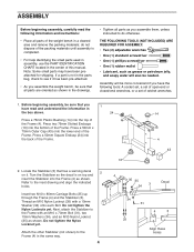
...lower end of this manual. Locate the Stabilizer (3) that has a warning decal 2 on top and insert the Stabilizer into the top of the weight bench in a cleared area and remove the packing materials; Turn the Stabilizer so the decal is completed. ¥ For help identifying the small parts used ...in assembly, use the PART IDENTIFICATION CHART located in the center of the Frame. Before beginning assembly, be needed. Press two 76mm Slotted Endcaps (16) into the back of the Frame. Thread an M10 Nylon Locknut (35) with an M10 x 70mm Bolt (31),...
...lower end of this manual. Locate the Stabilizer (3) that has a warning decal 2 on top and insert the Stabilizer into the top of the weight bench in a cleared area and remove the packing materials; Turn the Stabilizer so the decal is completed. ¥ For help identifying the small parts used ...in assembly, use the PART IDENTIFICATION CHART located in the center of the Frame. Before beginning assembly, be needed. Press two 76mm Slotted Endcaps (16) into the back of the Frame. Thread an M10 Nylon Locknut (35) with an M10 x 70mm Bolt (31),...
User Manual
Page 5
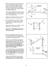
Identify the Right Upright (2) by noting the positions of the Right Upright (2); Press a 76mm Slotted Endcap (16) into the 2 top of the Adjustment Bar (9). Attach the Left Upright (not shown) to the other Stabilizer (not shown) in the ... the same manner. 4. Slide a 76mm Plastic Bushing (14) onto each end of the Right Upright. Do not overtighten the 14 Bolts; Make sure that step. Press the 76mm Plastic Bushing (14) firmly into the bottom of the adjustment brackets and the bolt holes near the lower end. Insert a 32mm Square Endcap...
Identify the Right Upright (2) by noting the positions of the Right Upright (2); Press a 76mm Slotted Endcap (16) into the 2 top of the Adjustment Bar (9). Attach the Left Upright (not shown) to the other Stabilizer (not shown) in the ... the same manner. 4. Slide a 76mm Plastic Bushing (14) onto each end of the Right Upright. Do not overtighten the 14 Bolts; Make sure that step. Press the 76mm Plastic Bushing (14) firmly into the bottom of the adjustment brackets and the bolt holes near the lower end. Insert a 32mm Square Endcap...
User Manual
Page 6
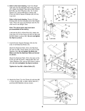
...x 40mm Bolts (27) and four M6 Washers (44). Do not overtighten the Nylon Locknut. Press a 25.4mm Endcap (22) into the indicated hole in the Leg Lever (21). Lubricate the M12 x 95mm Bolt (32...). Press two 50mm Square Endcaps (24) into the other end of the Weight Tube. Attach the Leg Lever ...M8 x 60mm Bolt (48), two 8mm Washers (46), the 13.5mm Spacer (47), and an M8 Nylon Locknut (45). Press the Leg Lever Bumper (23) into the Leg Lever. Tighten the four M6 x 40mm Bolts (27). 6 24 21 46 45...
...x 40mm Bolts (27) and four M6 Washers (44). Do not overtighten the Nylon Locknut. Press a 25.4mm Endcap (22) into the indicated hole in the Leg Lever (21). Lubricate the M12 x 95mm Bolt (32...). Press two 50mm Square Endcaps (24) into the other end of the Weight Tube. Attach the Leg Lever ...M8 x 60mm Bolt (48), two 8mm Washers (46), the 13.5mm Spacer (47), and an M8 Nylon Locknut (45). Press the Leg Lever Bumper (23) into the Leg Lever. Tighten the four M6 x 40mm Bolts (27). 6 24 21 46 45...
User Manual
Page 7
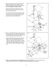
... bench are under the preacher curl weight rest. 17 37 4 4 33 11 11 11 13 33 Preacher 12 21 Curl Weight 33 13 Rest 11 11. Insert the Curl Post (5) into the Leg Lever (21). Press ...19mm Endcaps (33) into the indi- 9 cated hole in HOW TO ADJUST THE WEIGHT BENCH, beginning on the Frame (4). Make sure that all parts of...Insert an Adjustment Pin (17) through the Curl Post and the Frame. 6 5 44 44 29 35 10. Press a 19mm Endcap (33) into the welded tube on the next page. 7 Slide a Foam Pad (11) onto...
... bench are under the preacher curl weight rest. 17 37 4 4 33 11 11 11 13 33 Preacher 12 21 Curl Weight 33 13 Rest 11 11. Insert the Curl Post (5) into the Leg Lever (21). Press ...19mm Endcaps (33) into the indi- 9 cated hole in HOW TO ADJUST THE WEIGHT BENCH, beginning on the Frame (4). Make sure that all parts of...Insert an Adjustment Pin (17) through the Curl Post and the Frame. 6 5 44 44 29 35 10. Press a 19mm Endcap (33) into the welded tube on the next page. 7 Slide a Foam Pad (11) onto...


