AJSDC615 User Guide
Page 2
...service) instructions in a commercial environment. Warning: To assure continued FCC emission limit compliance, the user must use only shielded interface cables when connecting to both the AJ-SDC615 and AJ-SDC905. Do not recharge, disassemble or dispose of another battery may explode if mistreated. The exclamation... to dispose of this equipment could void the user's authority to Part 15 of these instructions apply to external units. RBRC FCC Note: This equipment has been tested and found to comply with the instruction manual, may be required to persons. Use of in...
...service) instructions in a commercial environment. Warning: To assure continued FCC emission limit compliance, the user must use only shielded interface cables when connecting to both the AJ-SDC615 and AJ-SDC905. Do not recharge, disassemble or dispose of another battery may explode if mistreated. The exclamation... to dispose of this equipment could void the user's authority to Part 15 of these instructions apply to external units. RBRC FCC Note: This equipment has been tested and found to comply with the instruction manual, may be required to persons. Use of in...
AJSDC615 User Guide
Page 3
... Chapter 3 Recording and playback ...... 19 3-1 Cassette tapes 19 3-2 Basic procedures 20 3-3 Scene-to-scene continuity 22 3-4 NEWS REC function SDC615 22 3-5 PRE-RECORDING function SDC905 ........ 23 3-6 INTERVAL REC function 23 3-7 RETAKE function 25 3-8 Rec-review function 25 3-9 Normal playback ... function 47 4-8-4 Allocating functions to the USER MAIN, USER1 and USER2 buttons 47 4-8-5 Setting the color temperature manually ....... 48 4-9 Data handling 48 4-9-1 Handling the setup card 48 4-9-2 Setup card operations 49 4-9-3 How to use the user data 52 4-9-4 How to use the ...
... Chapter 3 Recording and playback ...... 19 3-1 Cassette tapes 19 3-2 Basic procedures 20 3-3 Scene-to-scene continuity 22 3-4 NEWS REC function SDC615 22 3-5 PRE-RECORDING function SDC905 ........ 23 3-6 INTERVAL REC function 23 3-7 RETAKE function 25 3-8 Rec-review function 25 3-9 Normal playback ... function 47 4-8-4 Allocating functions to the USER MAIN, USER1 and USER2 buttons 47 4-8-5 Setting the color temperature manually ....... 48 4-9 Data handling 48 4-9-1 Handling the setup card 48 4-9-2 Setup card operations 49 4-9-3 How to use the user data 52 4-9-4 How to use the ...
AJSDC615 User Guide
Page 12
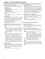
...details, refer to "4-8-4 Allocating functions to "4-8-5 Setting the color temperature manually." Shooting and recording (VTR unit) ; The MANUAL KNEE circuit operates. The AUTO KNEE circuit does not operate. For details, refer to the USER MAIN, USER1 and USER2 buttons." As the factory setting, the ...to the VTR unit, viewfinder and/or video monitor. For details, refer to "4-7-8 Marker check screen displays." : USER MAIN, USER 1 and USER 2 buttons A user setting can be allocated to the STBY position. 12 When the button is pressed again, the selected mode is pressed....
...details, refer to "4-8-4 Allocating functions to "4-8-5 Setting the color temperature manually." Shooting and recording (VTR unit) ; The MANUAL KNEE circuit operates. The AUTO KNEE circuit does not operate. For details, refer to the USER MAIN, USER1 and USER2 buttons." As the factory setting, the ...to the VTR unit, viewfinder and/or video monitor. For details, refer to "4-7-8 Marker check screen displays." : USER MAIN, USER 1 and USER 2 buttons A user setting can be allocated to the STBY position. 12 When the button is pressed again, the selected mode is pressed....

AJSDC615 User Guide
Page 62
... in such a way that is inherent to the camera. To adjust the white shading, release the digital zoom function first (by pressing again the USER button to flicker, use the filters and shutter. 4 Loosen the screw securing the F.f (flange focus) ring. Adjusting the white shading of the ... be marked as F.b (flange back) ring. 3 If the extender is attached to the lens, release the extender function. 4 Perform a menu operation to manual and open the screen from the VF page, check that the settings selected for the ZEBRA1 DETECT item, ZEBRA2 DETECT item and ZEBRA2 item match...
... in such a way that is inherent to the camera. To adjust the white shading, release the digital zoom function first (by pressing again the USER button to flicker, use the filters and shutter. 4 Loosen the screw securing the F.f (flange focus) ring. Adjusting the white shading of the ... be marked as F.b (flange back) ring. 3 If the extender is attached to the lens, release the extender function. 4 Perform a menu operation to manual and open the screen from the VF page, check that the settings selected for the ZEBRA1 DETECT item, ZEBRA2 DETECT item and ZEBRA2 item match...
AJSDC615 User Guide
Page 80
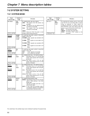
...set to 0% for the signals on the viewfinder. The underlining in the variable range column indicates the setting in which to inform the user that the unit is recording when a system using an extender or other device is configured and BOTH is selected as the 26PIN CONTROL ...1394 CU F E REC MODE SDC905 16:9/50M 4:3/50M 16:9/25M 4:3/25M CU F E ASPECT 16:9 SDC615 4:3 CU F E SET UP 50 SDC905 O% 7.5%A CU F E SET UP SDC615 SET UP 25 O% 7.5% 7.5%A SDC905 CU F E PB MODE SDC905 MANUAL AUTO CU F E Remarks For selecting the video input signals. CAM is always set when the power is...
...set to 0% for the signals on the viewfinder. The underlining in the variable range column indicates the setting in which to inform the user that the unit is recording when a system using an extender or other device is configured and BOTH is selected as the 26PIN CONTROL ...1394 CU F E REC MODE SDC905 16:9/50M 4:3/50M 16:9/25M 4:3/25M CU F E ASPECT 16:9 SDC615 4:3 CU F E SET UP 50 SDC905 O% 7.5%A CU F E SET UP SDC615 SET UP 25 O% 7.5% 7.5%A SDC905 CU F E PB MODE SDC905 MANUAL AUTO CU F E Remarks For selecting the video input signals. CAM is always set when the power is...
AJSDC615 User Guide
Page 100
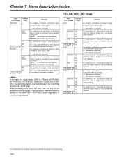
... is enabled. / : The selection is disabled. For selecting in 0.1 V steps the voltage at which the battery charge is to warn the user that the end of the remaining battery charge is approaching is determined by the setting on the screen regardless of a digital battery (PRO14, TRIM14...be set . Chapter 7 Menu description tables 7-8-4 BATTERY SETTING2 Item/ Data storage ENDURA80 CUF BP-L60/90 CUF Variable range 2 / AUTO MANUAL 11.0 : 13.6 : 15.0 2 / AUTO MANUAL 11.0 : 15.0 Remarks For enabling or disabling the selection made for the BATTERY SELECT item. 2 : The selection is enabled. / :...
... is enabled. / : The selection is disabled. For selecting in 0.1 V steps the voltage at which the battery charge is to warn the user that the end of the remaining battery charge is approaching is determined by the setting on the screen regardless of a digital battery (PRO14, TRIM14...be set . Chapter 7 Menu description tables 7-8-4 BATTERY SETTING2 Item/ Data storage ENDURA80 CUF BP-L60/90 CUF Variable range 2 / AUTO MANUAL 11.0 : 13.6 : 15.0 2 / AUTO MANUAL 11.0 : 15.0 Remarks For enabling or disabling the selection made for the BATTERY SELECT item. 2 : The selection is enabled. / :...


